Table of Contents
Advertisement
Quick Links
Advertisement
Table of Contents

Related Manuals for Planet IPOE-171S


Summary of Contents for Planet IPOE-171S
- Page 1 Industrial Ultra Power over Ethernet Splitter IPOE-171S User’s Manual...
-
Page 2: Table Of Contents
Table of Contents 1. Package Contents ............. 3 2. Product Features............... 4 3. Product Specifications ............5 4. Hardware Introduction ............8 Three-View Diagram ..........8 Product Front Panel ..........9 LED Indicators ............10 5. Hardware Installation ............11 Before Installation ..........11 4-pin Power Output Terminal Block ...... -
Page 3: Package Contents
1. Package Contents Thank you for purchasing PLANET Industrial Ultra Power over Ethernet Splitter, IPOE-171S. “Ultra PoE Splitter” mentioned in this manual refers to the IPOE-171S. Open the box of the Ultra PoE Splitter and carefully unpack it. The box should contain the following items: Ultra PoE Splitter x 1 User’s Manual x 1... -
Page 4: Product Features
2. Product Features Interface z 2-Port RJ45 interfaces 1-Port Data + Power input 1-Port Data output z 2 DC output (4-pin terminal block) z 1 DC 12V/24V DIP switch Power over Ethernet z Complies with ultra Power over Ethernet end-span and mid- span PDs z Complies with IEEE 802.3at Power over Ethernet Plus end- span/mid-span PD... -
Page 5: Product Specifications
3. P roduct Specifications Product IPOE-171S Hardware Specifications PoE Input 1 10/100/1000 BASE-T RJ45 Port “PoE (Data + Power) In” Data Output 1 10/100/1000 BASE-T RJ45 Port “Data Out” Interface DC Out Plug 1 removable 4-pin terminal block Connector DIP Switch 12V DC/24V DC output voltage Power Ready Green 802.3at... - Page 6 Installation DIN rail/wall mountable Enclosure IP30 metal case Power Requirements 50 ~ 56V DC PoE Power Output 12V DC, 4.5A (max.) (at 56V DC Input) 24V DC, 2.3A (max.) System on with PoE 3.7 watts input: Ethernet full loading 3.7 watts without DC output: Full loading with Power Consumption...
- Page 7 Standards Conformance IEEE 802.3 10BASE-T Ethernet IEEE 802.3u 100BASE-TX Fast Ethernet IEEE 802.3ab 1000BASE-T Gigabit Standards Compliance Ethernet IEEE 802.3at Power over Ethernet Plus IEEE 802.3af Power over Ethernet Regulatory Compliance FCC Part 15 Class A, CE Environment Operating Temperature -40~ 75 degrees C Storage Temperature -40~ 85 degrees C...
-
Page 8: Hardware Introduction
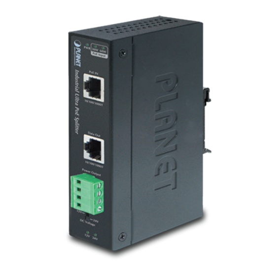
Mounting Kit DIN-Rail Kit Mounting Kit Bottom View Front View PWR 30W 60W PoE Input Side View PoE IN 10/100/1000T Data Out 10/100/1000T Power Output DC Voltage 12V 24V Dimensions ( unit = mm ) Figure 1: IPOE-171S Three-View Diagram... -
Page 9: Product Front Panel
4.2 Product Front Panel PWR 30W 60W PoE Input PoE IN 10/100/1000T Data Out 10/100/1000T Power Output DC Voltage 12V 24V Figure 2: Front Panel of IPOE-171S... -
Page 10: Led Indicators
4.3 LED Indicators Color Function Lights to indicate the port is Power Ready Green receiving 50~57V DC in-line power and ready for output Lights to indicate the ultra PoE Green splitter is working on 802.3at PoE mode Lights to indicate the ultra PoE Green splitter is working on Ultra PoE or 802.3bt PoE in... -
Page 11: Hardware Installation
5.1 Before Installation If there is no power socket in your network environment, the IPOE-171S provides DC power for this Ethernet Device conveniently and easily. The IPOE-171S will separate the power and data out. It provides two kinds of DC power output through... -
Page 12: 4-Pin Power Output Terminal Block
Power Output DC Voltage 12V 24V Figure 4: Terminal Block of IPOE-171S Two DC outputs are sharing 12V 2A or 24V 1A, totaling 55 watts DC output power, which means that DC1 + DC2 cannot be over the 55 Note watts DC output power. -
Page 13: Wiring The Power Outputs
5.3 Wiring the Power Outputs Please follow the steps below to insert the power wires. Step 1: Please find one terminal block connector within two DC power outputs shown below: DC Output 1 DC Output 2 The wire gauge for the terminal block should be in the range of 12 ~ 24 AWG. - Page 14 Connect the other point of DC power wires to the power devices. Tighten the wire-clamp screws for preventing the wires from loosening. Powered Device 1 Maximum Output 48 Watts Powered Device Total Maximum Output 48 Watts Powered Device Step 4: Install the terminal block on PLANET IPOE-171S Splitter.
- Page 15 Step 5: Connect the network copper cable (RJ45) from the Ultra PoE PSE and it will provide power to PLANET IPOE-171S Splitter and it will separate the power and data to the PDs (power devices). Please see the figure below: Ultra...
-
Page 16: Customer Support
7. Customer Support Thank you for purchasing PLANET products. You can browse our online FAQ resource at PLANET web site first to check if it could solve your issue. If you need more support information, please contact PLANET switch support team.