
Related Manuals for Trane LPC


Summary of Contents for Trane LPC
-
Page 1: Air Handler
Installation, Operation, and Maintenance Packaged Climate Changer Air Handler Model LPC “FO” and later design sequence 1,500 to 15,000 cfm LPC-SVX01C-EN July 2006... -
Page 2: General Information
Literature Change History refrigerant emissions while installing, Use this manual for Packaged Climate WARNING operating, or servicing equipment. Changer air handlers, model LPC. This is Always conserve refrigerants for Hazardous Voltage w/Capacitors! the first revision of this manual. It continued use. -
Page 3: Table Of Contents
Cross reference to related publications/information for model LPC units with Tracer AH540 controls: • Installation, Operation, and Programming Guide for Tracer AH540 Unit Controller, CNT -SVX05B-EN • Packaged Climate Changer Air Handler Catalog, CLCH-PRC007-EN Installation ……………………………………………………………2 general information ……………………………………………2 dimensions &... -
Page 4: General Information
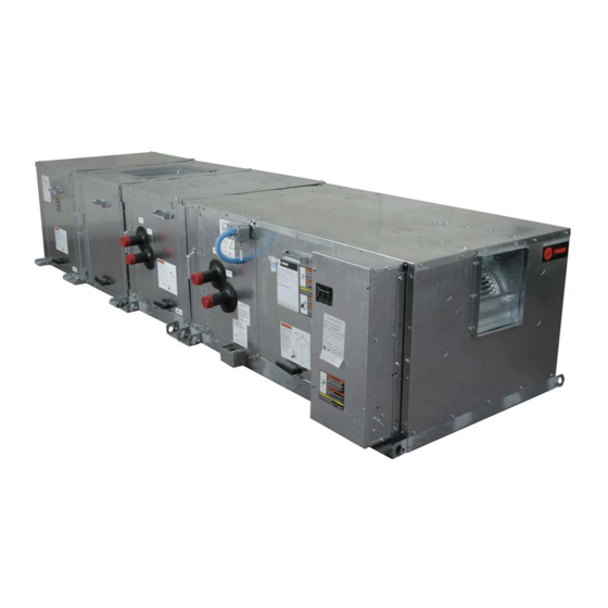
Environmental Accountability Policy Equipment capable of pulling a vacuum of 113 (R-113). Use only cleaning-solvents Trane urges that all HVAC servicers to less than 1,000 microns of mercury is that do not have ozone depletion factors. make every effort to eliminate, if possible, recommended. - Page 5 • variable frequency drive factory 12, or 14 fpi • Tracer AH540 mounted and wired • 1-row steam coil, 6 fpi, DDC controller reheat or preheat Figure I-GI-1. Packaged Climate Changer air handler unit components. Horizontal unit is shown. LPC-SVX01C-EN...
- Page 6 (Note 1). If specified, intended purpose of improving Trane provides ultraviolet lights (UV-C) as indoor air quality. High intensity a factory-engineered and installed option C-band ultraviolet light is known...
- Page 7 Available Fan Discharge Configurations Detail Horizontal Unit, Top Front Fan Discharge Vertical Unit, Back Top Vertical Unit, Top Back Horizontal Unit, Front Top Fan Discharge Vertical Unit, Front Top Vertical Unit, Top Front Fan Discharge Fan Discharge Fan Discharge Fan Discharge LPC-SVX01C-EN...
- Page 8 8. Minimum airflow limit is for units with hot water, steam, or electric heat. There is no minimum airflow for cooling only units. 9. Due to moisture carryover limits. 10. Coil weight based on 12 fpi coil. LPC-SVX01C-EN...
-
Page 9: Installation
Installation information Table I-GI-2. Available motor horsepower and unit voltage motor horsepower unit voltage 208/60/1 230/60/1 277/60/1 208/60/3 230/60/3 460/60/3 575/60/3 380/50/3 415/50/3 Table I-GI-3. Available motor horsepower by unit size motor horsepower unit size LPC-SVX01C-EN... -
Page 10: Lpc-Svx01C-En
45.0 54.0 – – – – 45.0 66.0 45.0 66.0 – – – – 51.3 68.0 51.5 68.0 – – – – 51.3 81.0 51.3 81.0 Note: 4-row coils have a " distributor. 6-row coils have a " distributor. LPC-SVX01C-EN... - Page 11 Following is a complete description of the Packaged Climate Changer model number. Each digit in the model number has a corresponding code that identifies specific unit options. LPC A A 08 F 2 F0 L L B 0 0 0 0...
- Page 12 E = angle filter section & mixing section 6 = MAS & field sup. NC mixing box act. F = flat filter section & mixing section 7 = DAS, MAS field sup. NO mix. box act. 8 = DAS, MAS field sup. NC mix. box act. LPC-SVX01C-EN...
- Page 13 2 = sensor w/Fahrenheit knob, on/cancel and comm jack 4 = sensor only 5 = field supplied zone sensor F = standalone operator display G = 1 & F H = 2 & F J = 4 & F K = 5 & F LPC-SVX01C-EN...
-
Page 14: Dimensions & Weights
Notes: 1. Weight of basic unit includes: cabinet, fan, average drive and filter. Add 9 pounds to basic weight for control box, if applicable 2. For units with factory installed VFD, an additional 11.26 inches needs to be added to the width of the unit to accomadote VFD 3. SW = Single Wall 4. DW = Double Wall LPC-SVX01C-EN... - Page 15 Notes: 1. Vertical units are only available in sizes 3 – 21. 2. For units with factory installed VFD, an additional 11.26 inches needs to be added to the width of the unit to accomadote VFD 3. SW = Single Wall 4. DW = Double Wall LPC-SVX01C-EN...
- Page 16 24.3 44.2 34.5 24.3 48.2 34.5 24.3 60.2 1 19 42.0 24.3 68.2 42.0 24.3 68.2 52.0 24.3 76.2 52.0 24.3 76.2 59.5 28.3 78.2 59.5 28.3 91.2 Notes: 1. SW = Single Wall 2. DW = Double Wall LPC-SVX01C-EN...
- Page 17 34.5 25.5 60.2 42.0 27 .3 68.2 1 12 42.0 27 .3 68.2 1 12 52.0 29.3 76.2 52.0 29.3 76.2 59.5 35.0 78.2 Airflow 59.5 35.0 91.2 Notes: 1. SW = Single Wall 2. DW = Double Wall LPC-SVX01C-EN...
- Page 18 11.6 2 - 25.7 x 53.0 59.5 35.0 78.2 25.5 58.0 10.1 2 - 25.7 x 58.0 59.5 35.0 91.2 25.5 68.0 11.6 2 - 25.7 x 68.0 Notes: 1. SW = Single Wall 2. DW = Double Wall LPC-SVX01C-EN...
- Page 19 74.0 10.1 48.47 x 74.0 25.5 x 58.0 59.5 37 .0 91.2 25.5 68.0 48.5 87 .0 53.0 87 .0 11.6 48.47 x 87 .0 25.5 x 68.0 Notes: 1. SW = Single Wall 2. DW = Double Wall LPC-SVX01C-EN...
- Page 20 CONNECTION LOCATION & 52.0 28.6 20.0 24.9 19.9 7 .6 73.0 SIZE TO BE DETERMINED BY TUTCO 52.0 33.6 20.0 24.9 24.9 7 .6 77 .0 59.5 32.0 20.0 25.3 23.3 7 .3 79.0 59.5 35.1 20.0 28.3 26.4 82.0 LPC-SVX01C-EN...
- Page 21 = 3.1” on unit sizes 3 and 6 = 3.6” on unit sizes 8–21 = 4.6” on unit sizes 25 & 30 K = 6.1” on unit sizes 3–21 = 8.1” on unit sizes 25 & 30 right hand AIR FLOW LPC-SVX01C-EN...
- Page 22 12, 14 17 , 21 25, 30 four-row coil 8, 10 12, 14 17 , 21 25, 30 six-row coil 8, 10 12, 14 17 , 21 25, 30 eight-row coil 8, 10 12, 14 17 , 21 25, 30 LPC-SVX01C-EN...
- Page 23 Note: Single circuit DX coils on unit sizes 3 – 10 have one distributor. Horizontal face split circuit DX coil connections, unit sizes 8 – 25, in. unit size D (LH) D (RH) four-row coil, ” distributor 12, 14 17 , 21 six-row coil, ” distributor 12, 14 17 , 21 LPC-SVX01C-EN...
- Page 24 NOTE: DX COIL CONNECTIONS ARE SWEAT STYLE Horizontal face split circuit DX coil connections, unit size 30, in. four-row coil, ” distributor six-row coil, ” distributor Note: Horizontal face split circuit DX coils on unit size 30 has four distributors. LPC-SVX01C-EN...
- Page 25 ” distributor 12,14 17 , 21 six-row coil, ” distributor 12,14 17 , 21 Note: DX intertwined coils, on unit sizes 8 – 14 have two distributors. Unit sizes 17 – 30 have four distributors. LPC-SVX01C-EN...
- Page 26 AIR FLOW AIR FLOW Steam coil connections, in. unit size B (LH) B (RH) F (LH) F (RH) 8, 10 12, 14 17 , 21 25, 30 Note: Unit sizes 17 – 30 with steam coils are two stacked coils. LPC-SVX01C-EN...
-
Page 27: Pre-Installation Considerations
Check with the carrier components provided by Trane or 2. Allow adequate service and code for their allotted time to submit a clearances as recommended in others, refer to the appropriate claim. -
Page 28: Rigging And Handling
All units must be installed level. 4. Coil piping and condensate drain requirements must be considered. Figure I-PC-2. Rotating Filter Door Swing Allow room for proper ductwork and electrical connections. Support all piping and ductwork independently of unit to prevent excess noise and vibration. LPC-SVX01C-EN... - Page 29 Installation considerations Fan Discharge Conversion The LPC Vertical Unit can be ordered in four discharge configurations: Top/Front, Front/Top, Top/Back, and Back/ Top Figure I-PC-4. Discharge Configurations. Field conversions from one configuration to another can be made for sizes 8 through 21 by modifying certain parts of the cabinet and by rotating the fan.
- Page 30 18. Reattach access doors. above the unit for the discharge replaced by mounting angles to join ductwork. the fan to the cabinet. Figure I-PC-5. Contact Service Parts for a Duct Extension Kit Figure I-PC-6 Service PArts for Angle/Access Kits LPC-SVX01C-EN...
-
Page 31: Mechanical Requirements
Table I-MR-1. Condensate Piping Sizes Unit Size Main Drain (in) 0.75 0.75 1.00 1.00 1.00 1.00 1.00 1.00 1.25 1.25 Main Drain (cm) 1.905 1.905 2.54 2.54 2.54 2.54 2.54 2.54 3.175 3.175 Auxiliary Drain (in.) 0.75 0.75 Auxiliary Drain (cm) 1.905 1.905 LPC-SVX01C-EN... - Page 32 LPC-SVX01C-EN...
- Page 33 The selected tube diameter must be as small as possible, while still providing at least 5°F [2.7°C] of subcooling at the expansion valve Coil throughout the operating envelope. Figure I-MR-3. Refrigerant Coil with Packed Elbow LPC-SVX01C-EN...
- Page 34 Components: Installing the suction line requires field installation of these components: an access port and possibly a suction filter. Position them as close to the compressor as possible. LPC-SVX01C-EN...
-
Page 35: Electrical Requirements
Transformer control box cover. Refer to the unit nameplate for unit specific electrical information, such as voltage, minimum circuit ampacity (MCA), and maximum fuse size (MFS). Main controller board Figure I-ER-1. Tracer AH540 Power Requirement LPC-SVX01C-EN... - Page 36 Installation requirements Table ER-2. LPC Electric Heat kW Limits, Min./Max Table ER-1. Electric heat voltage unit heater unit size voltage voltage voltage 208/60/1 6/18 7/18 8/28 230/60/1 6/11 6/20 7/20 8/30 277/60/1 6/13 6/24 7/24 8/38 208/60/3 6/13 6/26...
- Page 37 148.7 1450 254T 24.0 208/60/3 40.6 48.3 230/60/3 40.6 1760 48.3 460/60/3 20.3 150.5 21.0 575/60/3 16.2 1760 254T 16.6 400/50/3 1465 254-6T 24.0 208/60/3 1760 254-6T 61.9 230/60/3 1760 254-6T 61.9 460/60/3 27 .6 575/60/3 1760 254-6T 21.4 LPC-SVX01C-EN...
-
Page 38: Installation Procedure
Elasto-rib pads. Isolators or attached to one another on a separate Elasto-rib pads are field-supplied. skid from the main unit. These sections Figure I-IP-2. Floor installation have installation brackets on all four corners, similar to the main unit. LPC-SVX01C-EN... -
Page 39: Installation Procedure
÷ 2 = 106.1 lb. motor ÷ 2 = 21.5 lb. total corner B = 166.1 lb. total corner D = 81.5 lb. Figure I-IP-1. Corner weight calculation example: size 8 horizontal LPC with a right-hand motor/drive & control box. LPC-SVX01C-EN... - Page 40 Installation procedure Attaching optional sections to the model LPC main unit Step 1. Connect modules to flange on top of unit. Step 2. Use the flange on both sides of the unit to connect modules. Note: Gasketing is not required on this equipment.
- Page 41 Attach the corner brackets using a bolt and nut. Note: Gasketing is not required on these units. The Packaged Climate Changer is designed and tested to be used without gasketing. All screws, nuts, and bolts required for installation are field supplied. LPC-SVX01C-EN...
- Page 42 16 - 22 AWG 200 (60.96) unoccupied spaces. • Concealed pipes, air ducts, or chimneys in partition spaces behind the controller. VIEW WITH COVER REMOVED (NOT TO SCALE) Figure I-IP-3. Wall mounted zone sensor dimensions. LPC-SVX01C-EN...
-
Page 43: Installation Procedure
Note: LPC size 12 cannot be mated to size 12 MCC. Also, Figure I-IP-4. Transition Kit Installtion LPC LPC size 17 cannot be mated to size 17 MCC. Size 12 LPC must be mated to size 14 MCC. Size 17 LPC must be To install the transition kit, follow the steps mated to size 21 MCC. -
Page 44: Pre-Startup Requirements
• Solder the conductors and insulate length limitations can be extended (tape) the joint sufficiently when splicing via Rover™, Trane’s service tool. Peer-to- through the use of a link repeater. peer communication across controllers is communication wire. Do not use wire... - Page 45 Trane recommends or wrap could damage the wires wire. that only one type of wire be used for • Comm5 is not polarity sensitive. Trane inside the cable. the Comm5 communication link. • Do not run Comm5 cable alongside or recommends that the installer keep •...
- Page 46 Ensure all unit access panels are in settings. Refer to the Appendix. place and that all screws, nuts, and Ensure the fan rotates freely in the bolts are tightened to their proper correct direction. torques. Verify that a clean air filter is in place. LPC-SVX01C-EN...
-
Page 47: Operation
The Tracer AH540 controller operates as a Wiring To stand-alone controller or it can communi- Sensors & cate as part of a Trane Integrated Com- Actuators fort™ System (ICS). In the stand-alone configuration, Tracer AH540 receives operation commands from the: AH540 •... - Page 48 & bypass heating ventilation control economizer damper warmup functions mixed air temperature control X exhaust fan (on/off) DX cooling Figure O-GI-7 . Variable frequency drive electric heat (VFD) option dehumidification two-pipe changeover LPC-SVX01C-EN...
-
Page 49: Communication With Other Controllers
DX 3 or Electric 2 LED (green) DX 4 or Electric 1 LED (green) Service LED (red) Service Pin button Comm LED (yellow) Test button Status LED (green) Operator-display connector Universal analog input TB43 (IN13) Figure O-GI-8. Tracer AH540/541 main controller board CNT -SVX05B-EN LPC-SVX01C-EN... - Page 50 Operation information Figure O-GI-9. Tracer AH540 termination board LPC-SVX01C-EN...
-
Page 51: General Information
Alternately, use three twisted-pair wires. Trane recommends the following four-conductor wires: • Plenum 18 AWG, Trane part number 400-2059 • Plenum 22 AWG, Trane part number 400-2020 • Non-plenum, Trane part number 400- 1005 Figure O-GI-11. - Page 52 8. Feed the cable into the Tracer AH540/ 541 enclosure. 9. Attach the operator-display cable to the operator-display connector on the circuit board (see Figure O-GI-13). The operator display receives power from the Tracer AH540/541 and turns on automatically when it is connected to the controller. LPC-SVX01C-EN...
-
Page 53: Connecting The Portable Operator Display
— View, Alarm, Schedule, 4. Press the Calibrate Touch Screen start again. To accept the changes, Override, or Setup — to access the press the OK button. button. A screen with a target desired set of screens. appears. LPC-SVX01C-EN... - Page 54 6. To increase the contrast, press the disable security. buttons along the bottom row, in sequence, from left to right. To decrease the contrast, press the buttons from right to left. Press the Home button. The home screen appears. LPC-SVX01C-EN...
- Page 55 2 to 10 Vdc 20 mA TB15/2 GND ground TB16/1 not used 2 to 10 Vdc 20 mA TB16/2 ground 1 Each analog output can be configured for 0–10 Vdc or 2–10 Vdc operation, and normally open or normally closed. LPC-SVX01C-EN...
- Page 56 (2320Ω± 5%) is measured with a 10kW thermistor that IN 4 TB34/1 IN discharge air 10 kΩ -40 to 212°F is included with Trane zone sensors. The TB34/2 GND temperature thermistor Tracer AH540/541 receives the space IN 5 TB35/1 IN outdoor air 10 kΩ...
- Page 57 If the entering LPC-SVX01C-EN...
- Page 58 Temp Failure diagnostic if the signal is no static pressure input for constant-volume longer valid, but the diagnostic has no space temperature or constant-volume affect on controller operation. If the discharge air temperature control. sensor returns to a valid input, the controller automatically clears the diagnostic. LPC-SVX01C-EN...
-
Page 59: Binary Inputs
Note 1: When steam is the source of heat, the heat valve is cycled open and closed when the controller is shut down on a Low Temp Detect latching diagnostic. Cycling the steam valve helps prevent excessive cabinet temperatures. See steam valve cycling in the Sequence of Operation section for further details. LPC-SVX01C-EN... - Page 60 Table O-GI-12. Filter Status Configuration pied mode (only if the occupied bypass IN 11 timer = 0; see “Occupied bypass mode”). Configuration Contact Closed Contact Open Not used Clean Clean Normally closed Clean Dirty Normally open Dirty Clean LPC-SVX01C-EN...
- Page 61 During exhaust fan Coil defrost operation, differential pressure closes the Binary input IN12 can be configured as a normally open switch and confirms that coil defrost input. the fan is operating properly. See the “Coil defrost” section. LPC-SVX01C-EN...
- Page 62 • Timed override On request ON/CANCEL buttons on the link. • Timed override Cancel request Some Trane zone sensor modules include • Communication jack Service Pin message request timed override ON and CANCEL buttons. • Service pin message request...
-
Page 63: Sequence Of Operation
The Tracer AH540/541 controller must have a valid space temperature and discharge air temperature input to operate space temperature control. LPC-SVX01C-EN... - Page 64 Discharge air control gains Heating/cooling mode control The heating or cooling mode of the controller can be determined two ways: 1. Communicated request 2. Automatically by the controller Use capacity to drive actuators Figure O-SO-1. Space Temperature Control Block Diagram LPC-SVX01C-EN...
- Page 65 Note 2: The Tracer AH540 controller does not support emergency heat. Emergency heat is treated as Auto. Note 3: Fan-only operation allows the outdoor air damper to open to its minimum position based on occupancy. Economizing is not allowed. LPC-SVX01C-EN...
-
Page 66: Sequence Of Operation
(hard-wired) their minimum positions. setpoint. LPC-SVX01C-EN... - Page 67 Exceeding the motor temperature limit can cause premature failures. Table O-SO-5. Example of communicated values Discharge-air cooling setpoint input 50°F (10.0ºC) Discharge-air heating setpoint input None Effective heat cool mode Cool LPC-SVX01C-EN...
- Page 68 Effective discharge air Effective heat/cool mode temperature setpoint Discharge air temperature Discharge air temperature (wired sensor) control loop Calculate heat/cool capacity Discharge air control gains Use capacity to Figure O-SO-4. Discharge Air Temperature drive actuators Control Flow Diagram LPC-SVX01C-EN...
-
Page 69: Occupied Mode
See daytime warm up in configuration section of this manual. When the controller first powers up or after a reset, it makes an initial determi- nation if the discharge air temperature control mode should be heating or LPC-SVX01C-EN... - Page 70 Occupied standby is a mode in which the ON button on the Trane zone sensor. setpoint. controller has received an occupied request from Tracer Summit, but has also...
- Page 71 (nvoOccManCmd). ing to the unoccupied setpoints regard- Trane systems and zone sensors do not less of the hard-wired occupancy input communicate this information to the state. controller, but the Tracer AH540/541...
- Page 72 Operation operation Table O-SO-6. Effective occupancy arbitration for Tracer AH540/541 with operator display LPC-SVX01C-EN...
- Page 73 Operation operation continued Table O-SO-6 Effective occupancy arbitration for Tracer AH540/541 with operator display LPC-SVX01C-EN...
- Page 74 CANCEL button is discharge air temperature control, the pressed on the Trane zone sensor or the The daytime warmup terminate setpoint controller requires a space temperature occupied bypass time expires.
- Page 75 Cool-down can also be initiated by a • When entering water temperature If the controller is wired to a Trane zone building automation system with a mode sampling is initiated sensor, the user can change the supply command of pre-cool (optimal-start).
- Page 76 5 minutes) and closes it for 225 cooling setpoint in cooling mode. The controller uses analog modulating seconds. (0–10 Vdc or 2–10 Vdc) valves for heating or cooling operation. The controller supports one or two modulating valves for hydronic heating, steam heat, and LPC-SVX01C-EN...
- Page 77 During unit startup or outdoor air temperature is less than the communicated to the controller. changeover, the controller determines its face and bypass heating modulation • For cooling, entering water ability to deliver heating or cooling. The setpoint, the controller fully LPC-SVX01C-EN...
-
Page 78: Outdoor Air Damper Operation
Ventilation requirements are maintained by mixed-air temperature control depending on available heating and cooling sources, unit configuration, and mixed-air temperature control type (configurable). Low mixed-air temperatures can be a concern for units with hydronic heating and cooling. LPC-SVX01C-EN... - Page 79 Table O-SO-9. Mixed-air temperature control LPC-SVX01C-EN...
-
Page 80: Low Ambient Damper Lockout
2. Staged electric heat using a sequencer position is greater than or equal to the start setpoint can be selected to compen- For details, see “Staged electric heat”. LPC-SVX01C-EN... -
Page 81: Space Temperature Control
4. BO6: DX cooling stage 4 or Electric control. If mixed-air temperature control heat stage 1 is desired because of installed hydronic capacity, mixed-air temperature control should be used rather than mixed-air preheat control. LPC-SVX01C-EN... -
Page 82: Dx Cooling Operation
When outdoor air temperature tor refrigerant sensor or binary thermo- rises above 65°F , economizer operation is stat device on the first circuit or the circuit disabled. with the first cooling stage. As an option, LPC-SVX01C-EN... - Page 83 IN7 or IN12. If either • Analog thermistor input (evaporator control performance. LPC-SVX01C-EN...
-
Page 84: Unit Protection Strategies
Space RH Offset value. The controller will automatically revert back to unoccupied space temperature control. Space temperature and relative humidity are both controlled when dehumidification is active. Cooling capacity is modulated or staged to reduce space humidity, while heating capacity is modulated or staged to LPC-SVX01C-EN... - Page 85 Off. For example, override allows a building automation “IN7: Low-temperature detection or coil the Tracer AH540/541 is not able to run system such as Trane Tracer Summit defrost”) the air-handling unit because the run/stop to pressurize, depressurize, or purge the •...
-
Page 86: Interpreting Leds
(see “Service Pin message request”). output LED also applies to status of the LED light turns Off when the Test button end device. Table O-SO-16 describes the is pressed, and then it blinks (as LED states. described in Table O-SO-18) when the LPC-SVX01C-EN... - Page 87 Operation operation Table O-SO-15. Manual output test sequence Table O-SO-16. Binary output LEDs (green) LPC-SVX01C-EN...
- Page 88 The following locally wired sensor or communicated inputs are required for each control function listed in Table O- Table O-SO-18. Status LED (green) SO-20. If any one of the sensors does not exist, the controller operates the control function. LPC-SVX01C-EN...
- Page 89 Operation operation Table O-SO-19. Comm LED (yellow) Table O-SO-20. Required inputs LPC-SVX01C-EN...
-
Page 90: Maintenance
When you press the Test button, the controller exercises all outputs in a predefined sequence. The first and last outputs of the sequence reset the controller diagnostics. See “Performing a manual output test” . LPC-SVX01C-EN... - Page 91 Maintenance Table M-D-2. Tracer AH540/541 diagnostics LPC-SVX01C-EN...
- Page 92 Maintenance Table M-D-2 continued – Tracer AH540/541 diagnostics LPC-SVX01C-EN...
-
Page 93: Troubleshooting
• DX cooling binary outputs do not problems you might have with the Tracer energize AH540/541 controller: • Electric heat binary outputs do not • Fans do not energize energize Table M-T-1. Fan outputs do not energize LPC-SVX01C-EN... -
Page 94: Maintenance Troubleshooting
Maintenance troubleshooting Table M-T-2. Valves stay open LPC-SVX01C-EN... - Page 95 Maintenance troubleshooting Table M-T-3. Valves stay closed LPC-SVX01C-EN...
- Page 96 Maintenance troubleshooting Table M-T-4. Outdoor air damper stays open LPC-SVX01C-EN...
- Page 97 Maintenance Table M-T-5. Outdoor air damper stays closed LPC-SVX01C-EN...
- Page 98 Maintenance Table M-T-6. DX cooling binary outputs do not energize LPC-SVX01C-EN...
- Page 99 Maintenance Table M-T-7 . Electric heat binary outputs do not energize LPC-SVX01C-EN...
-
Page 100: Maintenance Procedures
Keep oil and grease away from the belt Fan Bearings because they may cause belt WARNING Fan bearings are permanently lubricated deterioration and slippage. Trane does not Hazardous Voltage w/Capacitors! and do not require additional lubrication. recommend belt dressing. Disconnect all electric power,... - Page 101 2. Wearing the appropriate personal contaminated materials and cleaning filter maintenance, and efficiency and dirt protective equipment, use a soft brush solution. load. Follow the suggested methods in to remove loose debris from both sides the following paragraphs. of the coil. LPC-SVX01C-EN...
- Page 102 For variable frequency drives or other energy storing components provided by Trane or others, refer to the appropriate manufacturer’s literature for allowable waiting periods for discharge of capacitors. Verify with an appropriate voltmeter that all capacitors have discharged.
- Page 103 Instructions for Changing Out Spring 6. Push the snubber bolt down though Unit Sizes 12 through 30: Isolators on LPC the isolation base into the isolation Units ranging in size from 12 to 30 use a bracket as far as it will go. This should Unit Sizes 3 through 10: 2”...
-
Page 104: Appendix
Maintenance Entering Water Temperature Sampling Function Figure M-A-1. Flowchart LPC-SVX01C-EN... - Page 105 Maintenance appendix Input Sensor Tables Table M-A-2. Trane zone sensor hard-wired setpoint thumbwheel Table M-A-3. Hard-wired 10 k Ω Ω Ω Ω Ω thermistor values LPC-SVX01C-EN...
- Page 106 Maintenance appendix Table M-A-4. Hard-wired 1k Ω Ω Ω Ω Ω mixed-air sensor Table M-A-5. Hard-wired relative humidity sensor values LPC-SVX01C-EN...
- Page 107 Maintenance appendix Table M-A-6. Hard-wired CO sensor values LPC-SVX01C-EN...
- Page 108 7 .34 Hex head set screw - 5/16 - 24 12.00 16.27 Ball joint set screw - 1/4 - 28 thread 3.33 4.52 Ball joint set screw - 5/16 - 24 12.00 16.27 Note: all torque values are +/- 5%. LPC-SVX01C-EN...
- Page 110 For more information contact your local office or e-mail us at comfort@trane.com Trane has a policy of continuous product improvement and reserves the right to change design and specifications without notice. Only qualified technicians should install and service equipment.