Viessmann VITOPLEX 200 Type SX2A Technical Manual
Oil/gas boilers 90 to 2000 kw
Hide thumbs
Also See for VITOPLEX 200 Type SX2A:
- Installation instructions manual (32 pages) ,
- Service instructions for contractors (32 pages) ,
- Installation instructions for contractors (28 pages)
Table of Contents
Advertisement
Quick Links
Advertisement
Table of Contents

Related Manuals for Viessmann VITOPLEX 200 Type SX2A


Summary of Contents for Viessmann VITOPLEX 200 Type SX2A
- Page 1 VIESMANN Oil/gas boilers 90 to 2000 kW Technical guide Design and operating information for hot water boilers up to 110 ºC to EN 12828, or up to 120 ºC to EN 12953 VITOPLEX 200 Type SX2A VITOPLEX 300 Type TX3A VITORADIAL 300-T Type VR3 VITOROND 200...
-
Page 2: Table Of Contents
Index Index Vitoplex 200, type SX2A, 90 to 1. 1 Product description ....................560 kW 1. 2 Operating conditions with Vitotronic boiler control units and Therm-Control .... Vitoplex 200, type SX2A, 700 to 2. 1 Product description ....................1950 kW 2. - Page 3 Index (cont.) 10. 9 Standard values for water quality ................44 ■ Heating systems with rated operating temperatures up to 100 ºC (VDI 2035) ..44 ■ Heating systems with permissible flow temperatures in excess of 100 ºC (VdTÜV DS 1466) ....................... 45 ■...
- Page 4 Index (cont.) 11. 8 On site connections ....................70 ■ Auxiliary functions for single boiler systems with the Vitotronic 200, type GW1 or Vitotronic 300, type GW2 ..................70 ■ Auxiliary functions for multi-boiler systems with the Vitotronic 300-K and Vitotronic 100, type GC1 via LON ..................
-
Page 5: Product Description
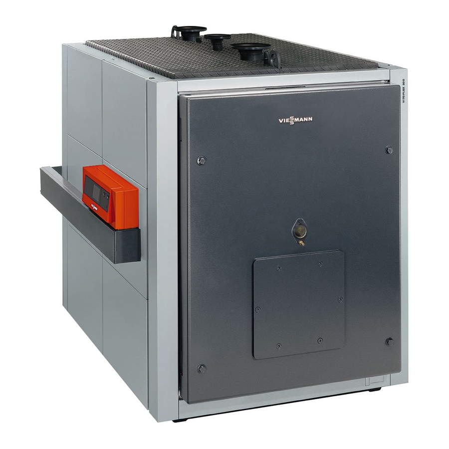
Vitoplex 200, type SX2A, 90 to 560 kW 1.1 Product description Low temperature oil/gas boiler ■ Three-pass boiler with low combustion chamber loading for clean For operation with modulating boiler water temperature combustion with low emissions. Permissible flow temperature (= safety temperature) up to 110 ºC (up ■... - Page 6 Vitoplex 200, type SX2A, 700 to 1950 kW 2.1 Product description Low temperature oil/gas boiler ■ Three-pass boiler with low combustion chamber loading, resulting in Three-pass boiler clean combustion with low emissions. For operation with modulating boiler water temperature ■ Wide water galleries and large water content provide excellent nat- Permissible flow temperature (= safety temperature) up to 110 °C (up ural circulation and safe heat transfer.
- Page 7 Vitoplex 300, type TX3A, 90 to 500 kW 3.1 Product description Low temperature oil/gas boiler ■ Optional stainless steel flue gas/water heat exchanger for higher Three-pass boiler with multi-layered convection heating surfaces standard seasonal efficiency [to DIN] through condensing technol- For operation with a modulating boiler water temperature ogy.
- Page 8 Vitoplex 300, type TX3A, 620 to 2000 kW 4.1 Product description Low temperature oil/gas boiler ■ Three-pass boiler with low combustion chamber loading, resulting in Three-pass boiler with multi-layered convection heating surfaces clean combustion with low emissions. For operation with a modulating boiler water temperature ■...
- Page 9 Vitoradial 300-T, type VR3, 101 to 335 kW 5.1 Product description Low temperature boiler with oil/gas condensing heat exchanger ■ Inox-Radial heat exchanger for condensing hot gases, matched to Three-pass boiler with multi-layered convection heating surfaces the compact boiler. and downstream Inox-Radial spiral heat exchanger ■...
- Page 10 Vitorond 200, type VD2A, 125 to 270 kW 6.1 Product description Low temperature oil/gas boiler ■ Three-pass boiler, enabling clean combustion with low emissions. Three-pass boiler as cast iron sectional design (available as a block ■ Eutectoplex heating surface for high operational reliability and a long or in individual sections) service life.
- Page 11 Vitorond 200, type VD2, 320 to 1080 kW 7.1 Product description Low temperature oil/gas boiler ■ Three-pass boiler, enabling clean combustion with low emissions. Three-pass boiler in individual cast iron sections ■ Eutectoplex heating surface for high operational reliability and a long For operation with modulating boiler water temperature service life.
-
Page 12: Burner 8. 1 Specification, Vitoflame 100, Type Veh Iii
Burner 8.1 Specification, Vitoflame 100, type VEH III Burner output stage 1/2 Corresponds to the rated thermal load of the boiler. Vitoflame 100 pressure-jet oil burner in conjunction with a Vitoplex 200 Rated boiler output Burner output 68/97 91/130 114/163 152/217 205/293 First/second stage... - Page 13 Burner (cont.) Vitoflame 100 pressure-jet oil burner in conjunction with a Vitoradial 300-T Rated output = 50/30°C = 80/60°C Burner output 68/98 88/125 106/152 137/196 179/254 228/326 First/second stage Burner type VEHIII-1TXA VEHIII-2TXA VEHIII-3TXA VEHIII-4TXA VEHIII-5TXA VEHIII-6TX Oil throughput Stage 1 kg/h 10.6 11.6...
- Page 14 Burner (cont.) A Service switch (for burner adjustment) P Fan motor B Hood adaptor R Fan housing C Quick-action fastener S Impeller D Electronic ignition T Inlet air silencer E Servomotor U Air regulating valve F Burner control unit V Blast tube connection G Return line W Flame tube H Suction line...
-
Page 15: Specification, Vitoflame 100, Type Vg Iii
Burner (cont.) 8.2 Specification, Vitoflame 100, type VG III Burner output stage 1/2 Connection values Corresponds to the rated thermal load of the boiler. relative to 1013 m bar and 15 °C gas temperature. Vitoflame 100 pressure-jet gas burner in conjunction with a Vitoplex Vitoplex 200 (type SX2) Vitoplex 300 (type TX3A) Rated output... - Page 16 Burner (cont.) Note The combination valve may be fitted on the r.h. or the l.h. side of the boiler. Vitoflame 100 pressure-jet gas burner in conjunction with a Vitorond 200 Rated output of the boiler Burner output 82/136 104/174 128/213 First/second stage Burner type VG III-3R...
- Page 17 Burner (cont.) A Gas shut-off valve B Boiler door Note The combination valve may be fitted on the r.h. or the l.h. side of the boiler. A Combination valve G Burner control unit B Quick-action fastener H Ignition transformer C Servomotor K Mixer assembly D Air pressure switch L Ignition electrode...
- Page 18 Burner (cont.) O Blast tube T Air regulating valve P Impeller U Service switch for burner adjustment R Inlet air silencer V Flange gasket S Burner hood W Ball shut-off valve VIESMANN OIL/GAS BOILERS...
-
Page 19: Installation Accessories 9. 1 Specification
Installation accessories 9.1 Specification Accessories for heating circuits Divicon heating circuit distributor for boilers up to 335 kW Specification Construction and function ■ 1 to 4 heating circuits can be connected to the flow distributor and ■ The flow distributor and return collector can optionally be arranged return collector. - Page 20 Installation accessories (cont.) Divicon heating circuit distributor, wall mounted For Vitoplex 200, 90 to 270 kW, Vitoplex 300, 90 to 300 kW, Vitoradial 300-T, 101 to 335 kW, Vitorond 200, 125 to 270 kW and Vitocrossal 200/300, 87 to 314 kW. = 307 1630 Drain...
- Page 21 Installation accessories (cont.) Heating circuit connections Heating circuit connection DN 25 and DN 32 (shown with mixer) Heating circuit connection DN 40 and DN 50 (shown with mixer) A Heating flow B Heating return C Ball valve D Check valve E Circulation pump F Three-way mixer A Heating flow...
- Page 22 Installation accessories (cont.) Heating circuit connection Speed range 600-2600 600-2600 1800-4800 1800-4800 Power consumption 36-89 36-89 18-290 18-290 Current 0.17-0.43 0.17-0.43 0.18-1.32 0.18-1.32 Head Heating circuit pump DN 25 and DN 32 max. max. min. min. Flow rate in m³/h Flow rate in m³/h Proportional pressure Constant pressure...
- Page 23 Installation accessories (cont.) Electrical connection Heating circuit pump DN 25 and DN 32 A Connecting cable with plug-in connector Electrical connection Heating circuit pump DN 40 and DN 50 Colour coding to DIN IEC 60757 black BK * black cable with imprint brown blue GNYE...
- Page 24 Installation accessories (cont.) Head Heating circuit pump DN 25 and DN 32 Flow rate in m³/h A Automatic adaptation function E Upper curve, constant pressure B Upper curve, proportional pressure F Pump stage 1 for manual setting C Lower curve, proportional pressure G Pump stage 2 for manual setting D Upper curve, constant pressure H Pump stage 3 for manual setting...
- Page 25 Installation accessories (cont.) Electrical connection Heating circuit pump DN 25 and DN 32 A Connecting cable with plug-in connector Electrical connection Heating circuit pump DN 40 and DN 50 Colour coding to DIN IEC 60757 black BK * black cable with imprint brown blue GNYE...
- Page 26 Installation accessories (cont.) Boiler circuit pressure drop Mixer pressure drop (Boiler + pipework + flow distributor and return collector + heating cir- cuit connection without mixer) Flow rate in m³/h A DN 25 B DN 32 C DN 40 D DN 50 Flow rate in m³/h Note For the resistances of the pipework between the boiler and distributor,...
-
Page 27: Design Information 10. 1 Delivery, Handling And Installation
Installation accessories (cont.) Heating circuit 3: 30 mbar + 22 mbar = 52 mbar Residual head of the individual heating circuits With Wilo circulation pump Heating circuit Head of the circulation pump (adjustable) mbar 100 to 400 100 to 280 100 to 760 Boiler circuit + heating circuit connection pressure drop mbar... -
Page 28: Load-Bearing Boiler Cover
70 ºC. adjusting the control thermostat. Safety temperatures Viessmann boilers comply with EN 303 and DIN 4702, and all are CE- ■ Permissible flow temperatures (= safety temperatures): designated. They are suitable for installation in sealed heating systems up to 110 ºC to EN 12828. -
Page 29: Pump-Controlled Pressure Maintaining Systems
Design information (cont.) Pump-controlled pressure maintaining systems In heating systems with automatic and in particular pump-controlled This reduces the frequency and level of pressure fluctuations. This pressure maintaining systems with integral deaerating, we recom- contributes considerably to improved operational reliability and longer mend the installation of a diaphragm expansion vessel (DEV) for each service life of the system components. -
Page 30: Sample Applications
Design information (cont.) Return temperature raising facility Boiler flue connection kit for the Vitorond For the Vitoplex up to 560 kW, we deliver a pre-assembled return tem- For the connection of the following system components: perature raising facility for installation to the boiler flow and return con- ■... -
Page 31: General Information
■ Natural gas, town gas and LPG according to DVGW Code of Practice pounds (the consistency of which can fluctuate considerably) and G 260/I and II [Germany] or local regulations. The Viessmann other aggressive gases. Vitoflame 100 pressure-jet gas burners are only suitable for opera- –... -
Page 32: Burners
Gas Appliances Directive. using the Vitotrans 300 flue gas/water heat exchangers. You cannot use the Viessmann pressure-jet oil and gas burners Vitoflame 100, 90 Unit burner to 300 kW in conjunction with the Vitotrans 300 flue gas/water heat Viessmann pressure-jet oil or gas burners are offered for the Vitoplex exchangers installed downstream of the boiler. -
Page 33: Sizing The Flue System
Design information (cont.) ≤ 20° > 20° x < 1,5 m x < 1,5 m If x < 1.5 m, then a ≥ 1.0 m If x < 1.5 m, then a ≥ 1.0 m Sizing the flue system Calculating the cross-sections of the flue gas system is a basic and ■... - Page 34 Design information (cont.) Diagram for round cross-sections (Schiedel) 2000 1500 1000 Effective height of the flue gas system The diagram shown is also a valid representation for other manufac- turers. The installing contractor should check how far this diagram can be applied to the flue systems offered by alternative manufacturers.
-
Page 35: Flue System For Condensing Boilers
Design information (cont.) Flue system for condensing boilers The condensing boiler cools the flue gases, subject to the heating The Vitoradial 300-T condensing boilers may also be connected to water return temperature, down into the condensing range. They then moisture-resistant chimneys. According to DIN EN 13384, the chimney leave the system with a relative humidity of 100 %. - Page 36 Design information (cont.) At least one inspection aperture for checking and cleaning as well as Note for checking the pressure must be provided in the flue system. A flue gas temperature protection is not required in conjunction with If the flue pipe is inaccessible from the roof, a second inspection aper- the Vitoradial 300-T.
-
Page 37: Ce Designation For The Pps Flue Gas Systems For The Vitoradial 300-T
Design information (cont.) CE designation for the PPs flue gas systems for the Vitoradial 300-T VIESMANN OIL/GAS BOILERS... -
Page 38: Open Flue Operation With The Vitoradial 300-T
Design information (cont.) Open flue operation with the Vitoradial 300-T A flue pipe between the condensing boiler and the duct, as well as for System size flue pipe Ø 150 and 200 mm. routing through the duct (type B23 to TRGI 2008, point 2.3.2), is A boiler flue connection must be ordered for the connection to the required for open flue operation with the Vitoradial 300-T. - Page 39 Design information (cont.) Support bend System size Dimension [mm] Ø a 7 mm A System size 150 or 200 Support rail VIESMANN OIL/GAS BOILERS...
- Page 40 Design information (cont.) Duct cover (Fixing material for securing the duct cover on the cover plate is part of the standard delivery) System size Dimension [mm] Ø a 7 mm Ø b □ Spacers (3 pce) System size Dimension [mm] 7 mm Pipe Pipe, 2 m long (2 pce)
- Page 41 Design information (cont.) Plain inspection piece (straight) System Dimension [mm] size 7 mm A System size 150 or 200 Simple bend (87º) System size Dimension [mm] 7 mm Ø c A System size 150 or 200 Simple bend (45º) System size Dimension [mm] 7 mm Ø...
- Page 42 Design information (cont.) Ventilation bezel System size Dimension [mm] 7 mm Ø d A Spacers Inspection bend (87°) System size Dimension [mm] 7 mm A System size 150 or 200 Boiler flue connection (order separately) Boiler flue connection 200/150 VIESMANN OIL/GAS BOILERS...
-
Page 43: Connecting A Plastic Flue Pipe (Pps) To A Moisture-Resistant Chimney (Mr Chimney Negative Pressure)
Design information (cont.) Boiler flue Dimension [mm] connection 7 mm 200/150 200/200 — Boiler flue connection 200/200 A Test port B Optional connection for a flue gas high limit safety cut-out Connecting a plastic flue pipe (PPs) to a moisture-resistant chimney (MR chimney, negative pressure) Boiler flue connection Flue pipe 2 m long... -
Page 44: Sound Insulation
The following is a summary of essential water qualities. system is influenced by the quality of the water. A chemical water treatment can be ordered from Viessmann for fill- In any event, the cost of a water treatment facility is less than the cost ing. -
Page 45: Heating Systems With Permissible Flow Temperatures In Excess Of 100 ºc (Vdtüv Ds 1466)
This measure must be carried out by the following conditions: Viessmann industrial services or a specialist company. Inspect the ■ The total of alkaline earths in the fill & top-up water exceeds the heating system for possible damage prior to returning it into use. It is standard value. -
Page 46: Using Antifreeze In Boilers
Using antifreeze in boilers Viessmann boilers are designed and built for water as a heat transfer ■ If the system is filled with antifreeze, it must be marked accordingly. medium. To protect boiler systems from frost, it may be necessary to ■... -
Page 47: Prevention Of Damage Through Corrosion On The Water Side
At every part of the heating system, even at the suction side of the We recommend you refer questions of water treatment to Viessmann pump and under all operating conditions, the system pressure should industrial services or an appropriate specialist. -
Page 48: Hydraulic Connection
Design information (cont.) The overall efficiency for the condensing unit, comprising the gas boiler Example: and the Vitotrans 300 flue gas/water heat exchanger results from add- Efficiency Vitoplex 300 = 96 % ing the boiler efficiency and the increase in efficiency as a result of the The increase in efficiency resulting from the Vitotrans 300 at 75/60 ºC = heat exchanger, which has been calculated for the respective system 9 % leads to a total efficiency for the condensing unit of... -
Page 49: Condensate And Neutralisation
■ Constant return temperature control A specific, matching boiler control unit is part of the standard delivery of the Viessmann boilers Vitoplex 200 and 300 as well as Vitocontrol control panels with weather-compensated control unit Vitorond 200. This ensures that the required low-end boiler water tem- Vitotronic 300-K, type MW1S, for 1 to 4 boilers and 2 heating circuits perature is maintained. -
Page 50: Single Boiler Systems
Control units (cont.) Single boiler systems Vitotronic 100, type GC1 Electronic boiler control unit ■ For constant boiler water temperature Weather-compensated operation in conjunction with the Vitocontrol control panel and integral heating circuit control unit Vitotronic 200- H, type HK1S/HK3S (see separate datasheet) Weather-compensated operation in conjunction with an external control unit ■... -
Page 51: Multi-Boiler Systems
Control units (cont.) Vitotronic 300, type GW2 Weather-compensated, digital boiler and heating circuit control unit: ■ For single boiler systems ■ For one system circuit and up to two heating circuits with mixer (a maximum of 32 Vitotronic 200-H heating circuit control units can be connected via the LON BUS) An extension kit is required for each heating circuit with mixer. - Page 52 Electronic boiler control unit Vitotronic 300- K ■ For every boiler in a multi-boiler system with the Vitotronic 300-K, type MW1 (Viessmann cascade control unit, supplied with one boiler) for every boiler in a multi-boiler system – with Vitocontrol control panel and integral weather-compensated cascade control unit Vitotronic 300-K, type MW1S, –...
-
Page 53: Switching Points
Control units (cont.) Vitotronic 300-K, type MW1 Weather-compensated, digital cascade and heating circuit control unit: Vitotronic 300- K ■ Type MW1S: For installation in control panels (see separate data- sheet). ■ For multi-boiler systems ■ With sequential boiler strategy ■ For up to two heating circuits with mixer (a further 32 Vitotronic 200- H heating circuit control units can be connected via the LON). -
Page 54: Boiler Water Temperature Sensor
5.8 m, fully wired IP rating IP 32 to EN 60529; ensure through appropriate design and installation Sensor type Viessmann Pt500 Permissible ambient temperature – during operation 0 to +90 °C – during storage and transport –20 to +70 °C... - Page 55 Control units (cont.) ■ Optolink laptop interface You can select the following operating programs with the program ■ Temperature controller keys: DIN TR 77708 ■ For single boiler systems – Heating and DHW DIN TR 96808 – Only DHW ■ High limit safety cut-out –...
-
Page 56: Delivered Condition
Control units (cont.) Delivered condition ■ Boiler water temperature sensor ■ Cylinder temperature sensor and circulation pump with check valve ■ 1 bag with technical documentation for regulating the cylinder temperature ■ Only for multi-boiler systems: – LON communication module and connecting cable for the data ■... - Page 57 Control units (cont.) Setting heating programs Specification The heating system frost protection (see frost protection function) applies to all heating programs. Rated voltage 230 V~ You can select the following operating programs with the program Rated frequency 50 Hz keys: Rated current 2 x 6 A ■...
-
Page 58: Vitotronic 300, Type Gw2, Part No. 7248 085
Control units (cont.) Delivered condition ■ Programming unit ■ Circulation pump with check valve for regulating the cylinder tem- ■ Outside temperature sensor perature ■ Boiler water temperature sensor ■ Cylinder temperature sensor ■ Vitotrans 222 primary store system with mixer assembly ■... - Page 59 Control units (cont.) Setting heating programs Slope The heating system frost protection (see frost protection function) applies to all heating programs. You can select the following operating programs with the program keys: ■ Heating and DHW ■ Only DHW ■ Standby mode Optional external changeover of heating program for all heating cir- cuits together or for selected heating circuits only.
-
Page 60: Vitotronic 300-K, Type Mw1, Part No. 7248 233
Control units (cont.) Delivered condition ■ Programming unit Communication ■ Outside temperature sensor The LON communication module (accessories) is required for com- ■ Boiler water temperature sensor munication with other control units. ■ Cylinder temperature sensor ■ Bag with technical documentation Heating system with DHW cylinder Order separately: ■... -
Page 61: Delivered Condition
Control units (cont.) ■ Heating and DHW Specification ■ Only DHW ■ Standby mode Rated voltage 230 V~ Optional external changeover of heating program for all heating cir- Rated frequency 50 Hz cuits together or for selected heating circuits only. Rated current Power consumption 10 W... -
Page 62: Control Unit Accessories
■ Mixer motor with connecting cable ■ Plug for the heating circuit pump and flow temperature sensor (con- tact temperature sensor) The mixer motor is mounted directly onto the Viessmann mixer DN 20 to 50 and R ½ to 1¼. Specification Cable length 4.2 m, fully wired... -
Page 63: Mixer Motor For Flanged Mixers
IP 32 to EN 60529; ensure through appropriate design through appropriate design and installation and installation Permissible ambient temperature Sensor type Viessmann Ni500 – during operation 0 to +40 °C Permissible ambient temperature – during storage and transport -20 to +65 °C – during operation 0 to +120 °C... -
Page 64: Immersion Temperature Sensor
3.8 m, fully wired IP rating IP 32 acc. to EN 60529 ensure through appropriate design/installation Sensor type Viessmann Ni500 Permissible ambient temperature – during operation 0 to +90 °C −20 to +70 °C – during storage and transport Immersion thermostat Part no. -
Page 65: Vitotrol 200
Control units (cont.) Vitotrol 200 Part no. 7450 017 Specification KM BUS subscriber Power supply via KM BUS The Vitotrol 200 remote control regulates the heating program for one Power consumption 0.2 W heating circuit and the required set room temperature in standard Protection class mode, from any room in the house. -
Page 66: Room Temperature Sensor
(back) to the chimney stack. – during operation 0 to +600 °C ■ Condensing boilers with Viessmann balanced flue system: – during storage and transport -20 to +70 °C Order the balanced flue pipe with connector for the flue gas temper- ature sensor separately. -
Page 67: Plug-In Adaptor For External Safety Equipment
Control units (cont.) Plug-in adaptor for external safety equipment Part no. 7143 526 Specification With cables (3.0 m long), plug aVG and aBÖ. Protection IP 20D to EN 60529; safe- guard through appropriate Up to 4 additional pieces of safety equipment may be connected, for design and installation example: Permissible ambient temperature... -
Page 68: Functions In Connection With The Function Extension 0 – 10 V (Accessory)
Control units (cont.) Functions in connection with the function extension 0 – 10 V (accessory) Functions Vitotronic 300-K 200-H 0 – 10 V input aVF Defaulting an additional set boiler water temperature – Boiler enable in multi-boiler systems – – –... -
Page 69: Sensor Well
– during storage and transport Sensor well Part no. 7819 693 For the cylinder temperature sensor, part of the standard delivery of R ½" x 200 mm Viessmann DHW cylinders. Contactor relay Part no. 7814 681 Specification Contactor in small casing. -
Page 70: Extension Of The Connecting Cable
Control units (cont.) Extension of the connecting cable ■ Installation spacing 7 to 14 m: on-site – 2 connecting cables (7.0 m long) ■ Installation distance 14 to 900 m with junction boxes: Part no. 7143 495 – 2 connecting cables (7.0 m long) –... -
Page 71: Auxiliary Functions For Multi-Boiler Systems With The Vitotronic 300-K And Vitotronic 100, Type Gc1 Via Lon
Control units (cont.) External changeover of multi-stage/modulating burners Set coding address "02" accordingly. ■ Contact A open: Modulating operation ■ Contact A closed: Two-stage operation Auxiliary functions for multi-boiler systems with the Vitotronic 300-K and Vitotronic 100, type GC1 via LON Plugs aVD and aVH at the Vitotronic 300-K External demand Closing contact C starts the burner or boiler subject to load. -
Page 72: Connection To On-Site Control Units To The Vitotronic 100, Type Gc1 In Single Boiler Systems
A safety temperature of 120 °C (EN12953) is only permissible with an additional, self-monitoring high limit safety cut-out. For an acces- sory pack for safety temperature 120 ºC, see Viessmann pricelist. Operation with a modulating burner A Burner stage 1 "ON"... -
Page 73: Boiler Sequence Control With On-Site Cascade Controller — Connections To The Vitotronic 100, Type Gc1
For an acces- plug lÖ on the burner. sory pack for safety temperature 120 ºC, see Viessmann pricelist. ■ Set the minimum temperature at the higher control unit with the modulation controller 5 K higher than the lower boiler water temper- ature;... -
Page 74: Hook-Up Of On-Site Control Equipment Via Lon
For an accessory The modulation (full load) is switched on only for maintaining the pack for safety temperature 120 ºC, see Viessmann pricelist. minimum temperature. The boiler water temperature is limited by the electronic maximum... -
Page 75: Appendix 12. 1 Safety Regulations And Requirements
97/23/EC as category IV (see Declaration of Conformity in the – internal inspection no later than 3 years after commissioning product documentation of Viessmann boilers), require a permit (water pressure test possible as alternative. For max. test by the appropriate authority (generally the Planning Authority in pressure, see type plate) your locality). -
Page 76: Gas Installation
Appendix (cont.) Gas installation The gas installation should be carried out by the registered installer in accordance with the technical connection requirements stipulated by the gas supply utility. Operate the system in accordance with the above conditions. Pipe connections All pipe connections to the boiler should be made free from stress and torque. -
Page 77: Checks As Part Of The Building Regulations Approval Process
Appendix (cont.) Fuel oil EL Natural gas Alternative gases Operating temperature ≤ 80 mg/m ≤ 80 mg/m flue gas flue gas ≤ 180 mg/m ≤ 100 mg/m < 110 ºC flue gas flue gas ≤ 200 mg/m ≤ 110 mg/m 110 ºC to ≤... -
Page 78: Keyword Index
Keyword index Anti-corrosion measures..............47 Halogenated hydrocarbons..............27 Attenuating airborne noise...............44 Handling...................27 Attenuating structure-borne noise............44 Health & Safety at Work Act (BetrSichV) [Germany].......75 Auxiliary functions..............70, 71 Heating circuit distributor , 29 ■ Divicon..................19 Heating circuit pump................29 Blocking, external...............70, 71 Heating connections.................29 Boiler blocking..................71 Heating program changeover.............70, 71 Boiler circuit pump................29 High limit safety cut-out..............31... - Page 79 Keyword index Safety equipment................30 Temperature sensor Safety precautions................28 ■ Outside temperature..............54 Safety temperature..............28, 31 ■ Room temperature................66 Saline water..................45 Tests according to the BetrSichV [Germany]........75 Set boiler water temperature............68 Therm-Control................5, 7, 8, 9 Shunt pump..................29 Thermostat Single boiler system.................72 ■ Contact temperature..............64 Single boiler systems...............50 ■...
- Page 80 Subject to technical modifications. Viessmann Werke GmbH&Co KG Viessmann Limited D-35107 Allendorf Hortonwood 30, Telford Telephone: +49 6452 70-0 Shropshire, TF1 7YP, GB Fax: +49 6452 70-2780 Telephone: +44 1952 675000 www.viessmann.com Fax: +44 1952 675040 E-mail: info-uk@viessmann.com VIESMANN OIL/GAS BOILERS...