Table of Contents
Advertisement
FK1874 B P0113OZ
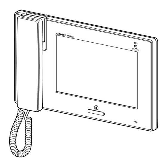
JM-4MED
HANDS-FREE COLOR VIDEO INTERCOM MASTER STATION
JMW-BA
LONG DISTANCE ADAPTOR
JM-8Z
DISTRIBUTION ADAPTOR
INSTALLATION MANUAL
JMW-BA
JM-4MED
JM-8Z
Thank you for selecting Aiphone for your communication and security needs. Please read this manual carefully before installation,
and keep it in a safe place for future reference. Also read the installation manuals for the other devices included in your system.
Please note that the illustrations in this manual may differ from the actual product.
Advertisement
Table of Contents

Related Manuals for Aiphone JM-4MED


Summary of Contents for Aiphone JM-4MED
- Page 1 JM-8Z Thank you for selecting Aiphone for your communication and security needs. Please read this manual carefully before installation, and keep it in a safe place for future reference. Also read the installation manuals for the other devices included in your system.
-
Page 2: Table Of Contents
CONTENTS PRECAUTIONS ........ 3 MOUNTING ........13 WARNING ........... 3 Mounting locations ......13 CAUTION ..........3 Mounting procedure ....... 14 GENERAL PRECAUTIONS ....3 SETTINGS AFTER INSTALLATION ......16 NOTICES ..........3 Setting list ........16 PACKAGE CONTENTS ....4 [INSTALL] menu ...... -
Page 3: Precautions
• We will under no conditions be liable for damage occurring due 5. For power supply, use Aiphone power supply model specifi ed to the inability to communicate due to malfunctions, problems, or for use with system. If non-specifi ed product is used, fi re or operational errors in this product. -
Page 4: Package Contents
PACKAGE CONTENTS Verify that the following parts are included. JM-4MED The unit Mounting screw x 4 Wood mounting screw x 4 12-pin option connector 4-pin option connector Installation Manual/Operation Manual JMW-BA JM-8Z The unit The unit CONNECTIONS Notes about handling cables Cables and connectors are not included with the products. -
Page 5: Wiring Distance
Wiring distance → P. 6) The wiring distance between the power supply and each unit differs depending on the power supply method. ( Station-to-station (daisy-chained) wiring Refer to "Selecting power supply method". (→P. 6) PS24 Home-run wiring PS24 PS24 PS24 PS24 [J] = Ja + Jb + Jc + --- + Jh Refer to "Selecting power supply method". -
Page 6: Selecting Power Supply Method
Selecting power supply method The system allows you to select from the following methods for supplying power to the system. The maximum wiring distance differs depending on the power supply method. You can also mix-and-match the methods 1 to 4 . 1 Supplying power directly to each unit from a single power supply CAUTION Master station... - Page 7 4 Supplying power to sub master stations via a distribution adaptor * The total wiring distance of residential stations is 300 m (980'). PS24 JM-8Z PS24 PS24 *1: The master station needs a power supply. *2: Up to four sub master stations can be supplied with one power supply. Use two power supplies for 5 - 7 sub master stations. 5 Mix-and-match methods * The total wiring distance of residential stations is 300 m (980').
-
Page 8: Basic System Connection
Both connection methods can be combined. Station-to-station (daisy-chained) wiring Master station (ID = 1) Sub master station 1 (ID = 2) Door station 1 JM-4MED JM-4HD JK-DA CAT5e (non-shielded) JK-DV JK-DVF Sub master station 2 (ID = 3) - Page 9 Home-run wiring CAT5e (non-shielded) Master station (ID = 1) Distribution adaptor JM-4MED Ø1.0mm, 18AWG 2 conductor cable JM-8Z Sub master station 1 (ID = 2) NP: Non-polarized JM-4HD P: Polarized Sub master station 2 (ID = 3) JM-4HD M (OUT)
-
Page 10: Expanding The System
The following are examples of additional connections to expand the system. ■ Extending the distance between the master station and a door station Connect a door station to the master station via JMW-BA, a long distance adaptor. Master station JM-4MED Long distance adaptor JMW-BA Video door station... - Page 11 Connect four door release devices to the master station via RY-3DL, a multiple door release adaptor. Electric door strike 2 - 4 contacts release the door where communication is established. Master station JM-4MED Door station 1 JK-DA etc. Electric door strike 1...
-
Page 12: Connecting External Devices (Using The Option Connectors)
Same as 1 . door station or camera as follows. Connect a device compatible with the format of video signals output from this connector. Aiphone video door station: NTSC • Security/utility input 3, External talk input NTSC camera: NTSC •... -
Page 13: Mounting
MOUNTING Mounting locations • Install this station in a place where the screen is not exposed • Allow at least 15 cm (6") above center of the mounting to direct sunlight. bracket for installation of the station. 15 cm (6") or more... -
Page 14: Mounting Procedure
Mounting procedure ■ JM-4MED <Back wiring> Fasten the mounting bracket to the wall. 3-gang box The unit Wires 83.5mm (3-5/16") Mounting bracket (pre-attached by factory) Mounting screw × 4 (included) CAT5e cable Mount the unit on the mounting bracket. Connect the CAT5e cable and wires to the unit. - Page 15 <Surface wiring> When the wiring is not coming through the wall, the cable and wires can be routed through the top or bottom of the cable inlet. Remove cable inlet plate on the upper part of the unit to allow passage of the wiring into the unit. Cable inlet plate CAT5e cable 92mm (3-5/8")
-
Page 16: Settings After Installation
SETTINGS AFTER INSTALLATION After installation, program the initial settings to activate the connected external devices. NOTES: These settings should be made by the installer before the system is used. • It is recommended to set the display language for the screen to the language needed. (Default language: English) •... -
Page 17: Setting For Inputs And Outputs
The [INSTALL] menu window is displayed. Setting for inputs and outputs Adjust the settings for inputs 1, 2, 3 and option outputs. ■ Settings for the usage of the inputs 1, 2 and/ or 3 [SECURITY SENSOR INPUTS] From th e [INSTALL] menu window, touch SECURITY SENSOR INPUTS . -
Page 18: Door Release Settings [Set Door Release]
■ Settings for the usage of the option outputs Door release settings [OPTION OUTPUT] [SET DOOR RELEASE] From th e [INSTALL] menu window, touch Adjust the settings for controlling the door release devices OPTION OUTPUT . connected to the "L1" and "L2" terminals. The [OPTION OUTPUT] window is displayed. -
Page 19: Initializing Station [Initialize]
TECHNICAL DATA AND PRECAUTIONS Technical data • JM-4MED Operating temperature 0 - 40°C (+32°F - +104°F) Dimensions 255 (W) x 145 (H) x 30 (D) mm 10-1/16" (W) x 5-3/4" (H) x 1-3/16" (D) Weight Approx. -
Page 20: Warranty
fi nal decision whether there is a defect in materials and/or workmanship; and whether or not the product is within the warranty. This warranty shall not apply to any Aiphone product which has been subject to misuse, neglect, accident, power surge, or to use in violation of instructions furnished, nor extended to units which have been repaired or altered outside of the factory.