Table of Contents
Advertisement
Operator's Manual
®
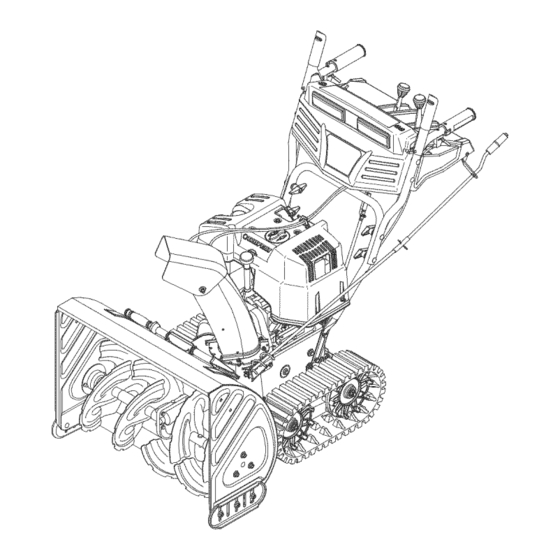
SNOW THROWER
MODELS
1028
1130
Storm Tracker
Model 1028 Shown
IMPORTANT:
READ SAFETY RULES AND INSTRUCTIONS
CAREFULLY
WARNING:
This unit is equipped with an internal combustion engine and should not be used on or near any unimproved forest-covered,
brush-covered
or grass-covered
land unless the engine's exhaust system is equipped with a spark arrester meeting applicable
local or state
laws (if any). If a spark arrester is used, it should be maintained in effective working order by the operator. In the State of California the above
is required by law (Section 4442 of the California Public Resources Code). Other states may have similar laws. Federal laws apply on federal
lands. A spark arrester for the muffler is available through your nearest engine authorized service dealer or contact the service department,
P.O. Box 361131 Cleveland, Ohio 44136-0019.
TROY-BILT
LLC, P.O. BOX 361131 CLEVELAND,
OHIO 44136-0019
FORM NO. 769-00395B
PRINTED IN U.S.A.
(6/04)
Advertisement
Table of Contents

Related Manuals for Troy-Bilt 1130


Summary of Contents for Troy-Bilt 1130
- Page 1 ® Operator's Manual SNOW THROWER MODELS 1028 1130 Storm Tracker Model 1028 Shown IMPORTANT: READ SAFETY RULES AND INSTRUCTIONS CAREFULLY WARNING: This unit is equipped with an internal combustion engine and should not be used on or near any unimproved forest-covered,...
- Page 2 TABLEOFCONTENTS Content Page Content Page Important Safe Operation Practices Servicing Your Snow Thrower Assembling Your Snow Thrower Trouble Shooting Know Your Snow Thrower Illustrated Parts Operating Your Snow Thrower Commercial Warranty Making Adjustments Residential Warranty Maintaining Your Snow Thrower FINDINGMODELNUMBER This Operator's Manual is an important part of your new snow thrower.
- Page 3 SECTION 1: IMPORTANT SAFEOPERATION P RACTICES Wk]uvlp erosr]qmv rxw]psru_qwvdi%_ _f@rqv/z k]fk_iqrwir@rz h g/frxg hqgdqjhuvkh shu:rqdo vdi%_ dqg_ustrsh@ ri I rxuvhddqg_vkhuvlUhdg_qg_r@rz _®I/vv_fJrqv_ vk_p dqxdoehirth dwhp s_qj_r rshui_h vk]:pdfk]qhlldlxth wcfrp s_ z i_ vkhvh_qv_mfJrqv_ d I#_hvx_]q shuvrqdo l_m_ IZ khq_ rx#:hh#k]uv I p er_ khhg_ z duql_j.
- Page 4 5. Never runanengine i ndoors orinapoorly v entilated MAINTENANCE A NDSTORAGE area. E ngine exhaust contains carbon m onoxide, an Never tamper with safety devices. Check their proper odorless and deadly g as. 6. Donot o perate m achine while under theinfluence of operation regularly.
- Page 5 SECTION 2: ASSEMBLING YOUR SNOW THROWER end of each cable) is attached to its actuator Unpacking bracket. • Remove screws from the top sides and ends of the Secure the upper handle and lower handle with the shipping crate. two plastic wing nuts, cupped washers and carriage •...
- Page 6 Chute Directional Control Ignition Key )ttle t Model 1028 Control i ji Fuel Shut-Off Valve Model 1130 equipped with one (1) *If Equipped Figure 5 WARNING: Read, understand, and follow DriveControl / AugerControl Lock all instructions warnings on the The drive control is located on the right handle.
- Page 7 Thedrivecontrol a lsolocksthe augercontrol s o you • Counterclockwise to discharge to the right. can turn the chute directional control without Clean-0utTool interrupting the snowthrowingprocess. I f the auger controlis engaged alongwith the drivecontrol,the The clean-out tool is designed to clear a clogged chute. operatorcan releasethe augercontrol(on the left Refer to page 10 for instructions on how to properly use handle) a ndthe augers will remain engaged.
- Page 8 Headlight Lever The headlight is on whenever the engine is running. TrackLock Lever The track lock lever is located on the right side of the snow thrower and is used to select the position of the Snow auger housing and the method of track operation. Move the lever to the right, then forward or backward to one of the three positions.
- Page 9 • Rotate chokeknob to FULL choke position (cold Pulling the starter rope will produce a loud clattering engine start). I fengine iswarm, p lace choke inOFF sound, which is not harmful to the engine or starter. position instead ofFULL. • To stop engine, move throttle control to "stop"...
- Page 10 • Confirm thattheauger hascompletely s topped few seconds to clear any remaining snow and ice rotating andshows NOsignsofmotion. from the chute assembly. IMPORTANT:If theauger shows ANYsigns ofrotating, DriftCutters Equipped) immediately return totheoperator's p osition andshut offtheengine. WaitforALLmoving parts tostopbefore Drift cutters should be used when operating the snow re-adjusting theauger control.
- Page 11 SECTION 5: MAKING ADJUSTMENTS WARNING: NEVER attempt to make any • Tip the snow thrower forward, allowing it to rest on adjustments while the engine is running, the auger housing. See Figure 9. except where specified in the operator's Frame Cover manual.
- Page 12 Skid Shoes ShiftRodAdjustment To adjust the shift rod, proceed as follows: The space between the shave plate and the ground can be adjusted. See Figure 12. • Remove the hairpin clip and slide the shift rod • For close snow removal on a smooth surface, raise connector up, to separate the upper shift rod from the lower shift rod.
- Page 13 Chute DirectionalControl The worm gear on the chute directional control should be greased with multipurpose automotive grease. Plastic Bearings *Model 1130 Bearing Shown Figure 14 To check the level of grease in the gear case, remove the vent plug. On Model 1028 only, you may, if necessary, add grease using a grease gun and the grease fitting on the side of the gear case.
- Page 14 Augers • The augers are secured to the spiral shaft with four (Model 1028) or six (Model 1130) shear pins and cotter pins. If you hit a hard foreign object or ice Flange Lock _Shave *Model1028...
- Page 15 DriveBelt • Drain the gasoline from the snow thrower, or place a piece of plastic film under the gas cap. • Follow the first six steps of the instructions for • Tip the snow thrower up and forward so that it rests servicing the auger belts.
- Page 16 • Lightly tap the hex nut to dislodge the ball bearing Shift Rod from the right side of frame before removing the hex Assembly _procket nut and bell washer from left end of shaft. Spacer Track Assembly Screws Friction Wheel Rubber Friction Wheel z Plates Figure 20...
- Page 17 • Follow the lubrication recommendations found in NOTE: Fuel stabilizer is an acceptable alternative the Maintenance Section. minimizing the formation of fuel gum deposits during storage. Do not drain carburetor if using fuel stabilizer. • Always store the snow thrower in a clean, dry area. •...
- Page 18 SECTION 9: PARTS LISTFORMODELS 1028 & 1130 Part of handle panel for reference only ,/¸...
- Page 19 Hex Bolt 3/8-24 x 1.5 747-1136tt Headlight Retainer 710-0599 TT Screw 1/4-20 x 0.5 735-0234* Rubber Grommet 711-0653 Clevis Pin 747-0697* Eye Bolt 712-0116 Jam Lock Nut 3/8-24 629-0059* Light Harness t Model 1028 * Model 1130 tt Model 1130 equipped with one (1)
- Page 20 Model 1 028 dl; ;';I_ i}_}...
- Page 21 Model 1 028 Ref. Ref. Part No. Part No. Part Description Part Description 714-0507 Cotter Pin 725-0157 Cable Tie 756-0178 Flat Idler 712-04065 Flange Lock Nut 3/8-16 784-5632B 741-0245 Auger Idler Arm Hex Flange Bearing 710-0347 790-00091 Skid Shoe Hex Cap Screw 3/8-16 x 1.75 738-0281 Shoulder Screw 721-0327...
- Page 22 Model 1 130...
- Page 23 Model 1 130 Ref. Ref. Part No. Part No. Part Description Part Description 714-0507 Cotter Pin 725-0157 Cable Tie 756-0178 Flat Idler 712-04065 Flange Lock Nut 3/8-16 784-5632B 741-0245 Auger Idler Arm Hex Flange Bearing 710-0347 790-00091 Skid Shoe Hex Cap Screw 3/8-16 x 1.75 738-0281 Shoulder Screw 721-0327...
- Page 24 Models 1028& 1130 Sup_ on engine 11 10 21 16...
- Page 25 Models 1028& 1130 Ref. Part No. Part Description 710-0896 Hex Washer Screw 1/4-14 x.625 731-1324 Belt Cover 732-0710 Extension Spring 710-0627 Hex Screw 5/16-24 x.75 710-3005 Hex Cap Screw 3/8-16 x 1.25 05896A Drive Clutch Idler Bracket 748-0234 Shoulder Spacer...
- Page 26 Models 1028& 1130 30 31 '\\ 23...
- Page 27 Models 1028&1130 Ref. Ref. Part No. Part No. Part Description Part Description 784-5648 Frame Cover 736-0270 Bell Washer.265 ID x.75 OD 736-0176 Flat Washer 1/4 ID x.93 OD 710-0896 Tap Screw 1/4-14 x.625 741-1111 748-0190 Spacer.508 ID x.75 OD Hex Flange Bearing...
- Page 28 Models 1028& 1130 "17...
- Page 29 Models 1028& 1130 Ref. Ref. Part No. Part No. Part Description Part Description 720-0223 618-0169A Grip Track/Steering Shaft Ass'y 710-0726 683-0024 Tap Screw, 5/16-12 x.750 Track Hub Ass'y 784-5642 Track Lockout Plate 713-0437 Chain 710-0157 741-0339 Hex Cap Screw, 5/16-24 x.75...
- Page 30 NOTES...
- Page 31 FOR: ® Routine maintenance items such as lubricants, filters, The limited warranty set forth below is given by Troy-Bilt LLC with respect to new merchandise used for commercial blade sharpening, tune-ups, brake adjustments, clutch purposes and purchased and used in the United States and/...
- Page 32 LIMITED WARRANTY FOR: ® deterioration of the exterior finish due to use or The limited warranty set forth below is given by Troy-Bilt LLC with respect to new merchandise purchased and used in the exposure. United States and/or its territories and possessions, and by Service completed by someone other than an authorized service dealer.