Advertisement
Safe Operation Practices • Set-Up • Operation • Maintenance • Service • Troubleshooting • Warranty
O
'
M
peratOr
s
anual
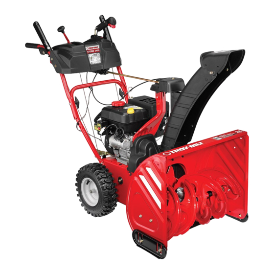
Two-Stage Snow Thrower — Storm 2410, 2420, 2620, 2625,
2840, 2890, & 3090
WARNING
READ AND FOLLOW ALL SAFETY RULES AND INSTRUCTIONS IN THIS MANUAL
BEFORE ATTEMPTING TO OPERATE THIS MACHINE.
FAILURE TO COMPLY WITH THESE INSTRUCTIONS MAY RESULT IN PERSONAL INJURY.
TROY-BILT LLC, P.O. BOX 361131 CLEVELAND, OHIO 44136-0019
Form No. 769-11748
(June 29 2016)
Printed In USA
Advertisement
Table of Contents

Related Manuals for Troy-Bilt Storm 2420


Summary of Contents for Troy-Bilt Storm 2420
- Page 1 READ AND FOLLOW ALL SAFETY RULES AND INSTRUCTIONS IN THIS MANUAL BEFORE ATTEMPTING TO OPERATE THIS MACHINE. FAILURE TO COMPLY WITH THESE INSTRUCTIONS MAY RESULT IN PERSONAL INJURY. TROY-BILT LLC, P.O. BOX 361131 CLEVELAND, OHIO 44136-0019 Form No. 769-11748 (June 29 2016)
-
Page 2: Table Of Contents
If you have difficulty assembling this product or have any questions regarding the controls, operation, or maintenance of this machine, you can seek help from the experts. Choose from the options below: ◊ Web: www.troybilt.com/equipment/troybilt ◊ Phone: (800) 828-5500 ◊ Mail: Troy-Bilt LLC• P.O. Box 361131 • Cleveland, OH • 44136-0019... -
Page 3: Safe Operation Practices
Important Safe Operation Practices WARNING! This symbol points out important safety instructions which, if not followed, could endanger the personal safety and/or property of yourself and others. Read and follow all instructions in this manual before attempting to operate this machine. Failure to comply with these instructions may result in personal injury. - Page 4 Safe Handling of Gasoline Never run an engine indoors or in a poorly ventilated area. Engine exhaust contains carbon monoxide, an odorless To avoid personal injury or property damage use extreme care and deadly gas. in handling gasoline. Gasoline is extremely flammable and the Do not operate machine while under the influence of vapors are explosive.
- Page 5 Clearing a Clogged Discharge Chute According to the Consumer Products Safety Commission (CPSC) and the U.S. Environmental Protection Agency (EPA), Hand contact with the rotating impeller inside the discharge this product has an Average Useful Life of seven (7) years, chute is the most common cause of injury associated with snow or 60 hours of operation.
- Page 6 Safety Symbols This page depicts and describes safety symbols that may appear on this product. Read, understand, and follow all instructions on the machine before attempting to assemble and operate. Symbol Description READ THE OPERATOR’S MANUAL(S) Read, understand, and follow all instructions in the manual(s) before attempting to assemble and operate WARNING—...
-
Page 7: Assembly & Set-Up
Assembly & Set-Up Contents of Carton • Snow Thrower (1) • Replacement Auger Shear Pins (2) • Chute Assembly (1) • Snow Thrower Operator’s Manual (1) • Product Registration Card (1) • Chute Control Rod† (1) • Engine Manual (1) †... - Page 8 Chute Assembly and Directional Control Close the flange keepers to secure the chute assembly to the chute base. The flange keepers will click into place (Models 2420, 2620, 2625 and 2840) when properly secure. See Figure 3-4. Remove cotter pin, wing nut and hex screw from chute NOTE: If the flange keepers will not easily click into place, control head.
- Page 9 Place chute onto chute base and ensure chute control Rotate the joystick to the one o’clock position so that the rod is positioned under the handle panel. Install hex bolt silver indicator arrow on the pinion gear below the control previously removed, but do not secure with wing nut at panel faces upward.
- Page 10 Overhead Chute Control Assembly (Models 2890 & 3090) Push the chute control rod toward the control panel until the hole in the rod lines up with the hole in the chute Remove wing nut and hex screw from chute control control input closest to the chute control head and insert assembly and clevis pin and cotter pin from chute support the cotter pin.
- Page 11 Finish securing chute control assembly to chute support Remove the hairpin clip from the rear of the chute control bracket with wing nut and hex screw removed earlier. assembly. See Figure 3-18a. See Figure 3-16. Insert chute directional control rod into rear of the chute control assembly.
- Page 12 Adjustments Chute Clean-Out Tool The chute clean-out tool is fastened to the top of the auger Skid Shoes housing with a mounting clip and a cable tie at the factory. Cut The snow thrower skid shoes are adjusted upward at the factory the cable tie before operating the snow thrower.
- Page 13 Chute Assembly (Models 2410, 2420, 2620 and 2625) Auger Control NOTE: The upper chute on model 2840 is also controlled by the WARNING! Prior to operating your snow thrower, 4-way Chute Directional Control. See Figure 4-1. carefully read and follow all instructions below. Perform all adjustments to verify your snow thrower The distance snow is thrown can be adjusted by changing the is operating safely and properly.
-
Page 14: Controls
Controls and Features 4-Way/2-Way Chute Directional Control † Drive Control Auger Control Shift Lever Heated Grips † Steering Trigger † Headlight † Overhead Chute Directional Control † Chute Assembly Chute Clean Standard Chute Out Tool Directional Control † Skid Shoe Augers †... - Page 15 Auger Control Standard Chute Directional Control (If so equipped) The auger control is located on the left handle. Squeeze the control grip against the handle to engage the augers and start snow throwing action. Release to stop. Drive Control / Auger Clutch Lock (If so equipped) The chute directional control is located on left side of the snow thrower.
- Page 16 4-Way Chute Directional Control Steering Trigger Controls (If so equipped) (If so equipped) The left and right wheel steering trigger controls are located on the underside of the handles. The 4-way chute directional control is located on the left side of •...
-
Page 17: Operation
Operation Starting and Stopping the Engine Replacing Shear Pins Refer to the Engine Operator’s Manual packed with your snow The augers are secured to the spiral shaft with shear pins and thrower for instructions on starting and stopping the engine. bow-tie cotter pins. -
Page 18: Maintenance & Adjustment
Maintenance & Adjustments Maintenance Lubrication Engine Gear Shaft Refer to the Engine Operator’s Manual. The gear (hex) shaft should be lubricated at least once a season or after every twenty-five (25) hours of operation. Shave Plate and Skid Shoes Allow the engine to run until it is out of fuel. The shave plate and skid shoes on the bottom of the snow Carefully pivot the snow thrower up and forward so that it thrower are subject to wear. - Page 19 Auger Shaft Apply a light coating of Bostik Regular Grade Never-Seez® to the hex shaft. See Figure 6-3. At least once a season, remove the shear pins from the auger shaft. Spray lubricant inside the shaft and around the spacers and the flange bearings found at either end of the shaft.
- Page 20 Auger Control Pivot the bracket downward to take up slack in the cable. Retighten the hex nut. Refer to the Assembly and Set-up section for instructions on adjusting the auger control cable. Drive Control Chute Assembly When the drive control is released and in the disengaged “up” position, the cable should have very little slack.
- Page 21 Chute Control Rod (Models 2420, 2620, 2625, and 2840) Chute Bracket Adjustment (Model 2410) To adjust the chute control rod, proceed as follows: If the spiral at the bottom of the chute directional control is not fully engaging with the chute assembly, the chute bracket can be Remove the cotter pin from the hole closest to the chute adjusted.
-
Page 22: Service
Service Belt Replacement Carefully pivot the snow thrower up and forward so that it rests on the auger housing. Auger Belt Remove the frame cover from the underside of the snow thrower by removing the self-tapping screws which secure To remove and replace your snow thrower’s auger belt, proceed it. - Page 23 Remove the belt from around the auger pulley, and slip the To inspect the friction wheel, proceed as follows: belt between the support bracket and the auger pulley. Allow the engine to run until it is out of fuel. Do not See Figure 7-5.
- Page 24 NOTE: Be careful not to damage the threads on the shaft. If you’re disassembling the friction wheel and replacing only the rubber ring, proceed as follows: NOTE: Not all friction wheels are serviceable. If this is the case, simply replace the friction wheel assembly. Remove the four screws which secure the friction wheel’s side plates together.
-
Page 25: Troubleshooting
Troubleshooting Problem Cause Remedy Engine fails to start 1. Choke not in CHOKE position. 1. Move choke to CHOKE position. 2. Spark plug wire disconnected. 2. Connect wire to spark plug. 3. Fuel tank empty or stale fuel. 3. Fill tank with clean, fresh gasoline. 4. -
Page 26: Replacement Parts
Replacement Parts Component Part Number and Description 954-04050A Auger Drive Belt (Storm 2410, Storm 2420, Storm 2620, & Storm 2625) 954-04195A Auger Drive Belt (Storm 2840, Storm 2890, & Storm 3090) 954-04260 Wheel Drive Belt (Storm 2410, Storm 2420, Storm 2620, &... -
Page 27: Attachments
Attachments & Accessories The following attachments and accessories are available for your Troy-Bilt snow thrower. Phone (800) 828-5500 for information regarding compatibility, price and availability (have your full model number and serial number ready). Model Number Description 929-0071A Extension Cord, 110V... - Page 28 MTD LLC, P.O. BOX 361131 CLEVELAND, OHIO 44136-0019...