
Related Manuals for MTD 19A70020OEM


Summary of Contents for MTD 19A70020OEM
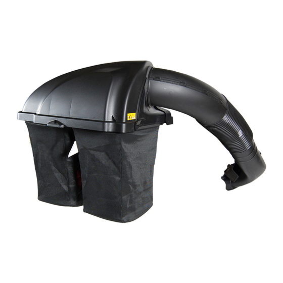
- Page 1 OPER roR's Twin Rear Bagger =Model No. 19A70020OEM MTD LLC, P.O. BOX 361131 CLEVELAND, OHiO 44136=0019 PrintedIn USA FORMNO. 769-06866 January 18,2011...
-
Page 2: Record Product Information
Choose from the options below: Visit us on the web at www.mtdproducts.com Call a Customer Support Representative at (800) 800-7310 or (330) 220-4683 Write us at MTD LLC • RO. Box 361131 • Cleveland, OH • 44136-0019... -
Page 3: Important Safe Operation Practices
Important SafeOperation Practices WARNING! This symbol points out important safety instructions which, if not followed, could endanger the personal safety and/or property of yourself and others. Read and follow all instructions in this manual before attempting to operate this machine. Failure to comply with these instructions may result in personal... -
Page 4: Safety Symbols
3. Use slow speed. Choose alow enough speed s etting s o GeneralService that y ou willnot h ave t ostop orshift w hile ontheslope. Before cleaning, repairing, or inspecting, make certain the Tires m ay lose traction onslopes even though t he brakes are functioning properly. - Page 5 this level with a vertical tree... Sight and hold or a corner of a building... or a fence post d along d " ' Otted_ .._iine_ ( represents a 10oslope) ¢N £ 10 ° Usethis page as a guide to determine slopes where you [nay safely operate your mower with a grass bag attachment installed.
-
Page 6: Contents Of Carton
Contents of Carton Before beginning installation, remove all parts from the carton to make sure everything is present. Carton contents are listed below and shown in Fig. 3-1. Three hardware packs are included in this kit and are detailed on the following page. -
Page 7: Contents Of Hardware Pack
CONTENTS OF HARDWARE PACK This grass collectorkit is shippedwith threeloosehardwarepacksenclosedand one set of hardwareincludedin the mountingbracketkit. Pleasecheckyourhardwarepacksagainstthe illustrationsbelow.The quantitiesfor each item is listedin parenthesis. Hardware Pack689-00095 Hardware Pack689-00092B 723-04008 [_(4) _(4) 711-05063 710-3008 712-04063 736-0204 712-04065 714-04040 711-0332 ,_(1) _(2) 710-3022 714-04023 911-04069... -
Page 8: Assembly And Installation
Assembly & installation NOTE: References to left, right, front and rear of the tractor are from the operator's position, unless otherwise stated. Before assembly, place the tractor on a firm, level surface, disengage the PTO, stop the tractor engine and set the parking brake. - Page 9 Install the bagger hanger assembly onto the mounting Mount Assembly onTractor assembly on the tractor by hooking it over the hitch plate Install mounting assembly on tractor as follows: between the two tabs. See Fig. 4-6. Slide the mounting bracket assembly along the frame rails of the tractor until the hooks in the mounting...
- Page 10 Installingthe Weight Bar Assembling RemainingBaggerComponents Install the weight bar onto the front of the tractor's foot rest Now that the mounting brackets are assembled and are in place using two 710-3022 hex screws and 712-04065 hex flange lock on the tractor, follow these steps to assemble the remaining nuts from Hardware Pack 689-00095.
- Page 11 Figure 4=13 Figure 4=11 Install the bagger cover onto the bag support assembly, seen in Fig. 4-12. The plastic cover goes inside of the two mounting tabs. Figure 4=14 Open Hood by pushing in on the rear, right-side tab with your right hand, as seen in 1 of Fig.
- Page 12 Install both bag assemblies onto the bag support brackets Install a grass-catcher pin (911-04069) from hardware pack by inserting the front edge in first, as seen in 1 of Fig. 689-00092B into the hole provided in the upper portion of the 4-16, and setting the back edge down until it fits into the chute elbow and secure with a flange lock nut (712-3027).
- Page 13 Install the chute tube extension onto the chute elbow by lining up the tabs and sliding the adapter over the chute elbow, as in Fig. 4-22. Secure the chute adapter stretching the chute strap and hooking it onto the grass- catcher pin previously installed.
- Page 14 With the grass catcher cover open, install the discharge Nete:The groove on the upper chute should be aligned chute over the chute extension tube, as seen in Fig. 4-24, with the upper chute support, as seen in the inset of Fig. 4-25.
-
Page 15: Operation
Operation Empty the grass clippings at a proper disposal site, use the BaggerUsage handle at the bottom of each grass bag. Holding the bag NOTE:When both grass bags are full, place the tractor on a firm, firmly, empty the contents level surface, disengage the PTO, turn the tractor engine off and... - Page 16 19A700200EM PartsList This bracket kit not needed for installation on this unit.
- Page 17 Part Number Ref,I Description 931-04291 Upper Chute Assembly 931-04292 Twin Bagger Cover Assembly 731-06497 Upper Chute Support 731-06504 Bagger Cover Screen 710-0276 Carriage Screw, 5/16-18 x 1.00" 710-3008 Hex Head Screw, 5/16-18 x .75" 911-0332 Clevis Pin, .50" Dia. 964-04096A Grass-bag Assembly 683-04461A-0637 Twin Bag Support...
-
Page 20: Limited Warranty
MANUFACTURER'S LiMiTED WARRANTY The limited warranty set forth below is given by MTD LLC with b. Routine maintenance items such as lubricants, filters, blade respect to new merchandise purchased and used in the United States sharpening, tune-ups, brake adjustments, clutch adjustments,...