Table of Contents
Advertisement
Advertisement
Table of Contents

Related Manuals for Icom IC-E208


Summary of Contents for Icom IC-E208
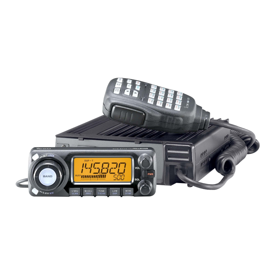
- Page 1 INSTRUCTION MANUAL VHF/UHF FM TRANSCEIVER iE208...
-
Page 2: Explicit Definitions
We want to take a couple of moments of your time to thank the IC-E208. you for making your IC-E208 your radio of choice, and hope you agree with Icom’s philosophy of “technology first.” Many hours of research and development went into the design of EXPLICIT DEFINITIONS your IC-E208. - Page 3 If an incorrect connection is made after cutting, the transceiver when cleaning, as they can damage the transceiver’s surfaces. may be damaged. Icom microphones only (supplied or optional). Other manu- NEVER expose the transceiver to rain, snow or any liquids. The facturer’s microphones have different pin assignments and may dam-...
-
Page 4: Table Of Contents
SUPPLIED ACCESSORIES TABLE OF CONTENTS FOREWORD ................... i IMPORTANT .................... i EXPLICIT DEFINITIONS ................. i PRECAUTION ..................ii SUPPLIED ACCESSORIES ..............iii TABLE OF CONTENTS ................. iii QUICK REFERENCE GUIDE ............. I–X I Installation ..................I I Your first contact ................VII I Repeater operation ............... - Page 5 I One-touch PTT function ............... 18 9 DTMF MEMORY ENCODER ............. 47–50 I Audio mute function ..............18 I Programming a DTMF code ............47 I Transmitting a DTMF code ............49 4 REPEATER OPERATION ............19–25 I General ..................19 I DTMF speed ................
-
Page 6: Quick Reference Guide
QUICK REFERENCE GUIDE I Installation D Installation methods • Single body installation • Remote installation Front panel Transceiver Main unit • The supplied mounting bracket (or optional MB-17A) can be • The supplied OPC-600R can be used for SEPARATION CABLE used for the main unit installation. -
Page 7: Using The Mounting Bracket
@@ QQ @ Q @ Q Mounting nut Flat washer Main unit When using self-tapping screws 25˚ Controller Main unit Main unit IMPORTANT! Detailed installation notes for Icom mobile transceivers to be fitted into vehicles are available. Contact your Icom dealer or distributor. -
Page 8: Microphone Connection
QUICK REFERENCE GUIDE wConnect a separation cable between the controller and D Microphone connection main unit using the supplied screws as illustrated below. Connect the supplied microphone as illustrated below. • Controller’s rear panel • Main unit D Separation cable connection Using the supplied separation cable (3.5 m) or the optional separation cable (7 m) the controller can be separated from the main unit, doubling as a remote controller. - Page 9 2 screws when the mounting base is used. MB-58 IC-E208 remote controller Bracket When using self- tapping screws. • When using the optional MB-65...
-
Page 10: Battery Connection
• CONNECTING TO A DC POWER SUPPLY Attach a rubber grommet when passing the DC power cable through a metal plate to prevent a short circuit. • CONNECTING TO A DC POWER SOURCE IC-E208 Grommet IC-E208 DC power supply 13.8 V −... -
Page 11: Antenna Installation
QUICK REFERENCE GUIDE D Antenna installation • Antenna connector The antenna uses a PL-259 connector. • Antenna location To obtain maximum performance from the transceiver, select • PL-259 CONNECTOR a high-quality antenna and mount it in a good location. A non- q Slide the coupling ring 30 mm radial antenna should be used when using a magnetic mount. -
Page 12: I Your First Contact
I Your first contact 2. Selecting the operating frequency band Now that you have your IC-E208 installed in your car or shack, you are probably excited to get on the air. We would The IC-E208 has 2 m and 70 cm transmittable bands. - Page 13 QUICK REFERENCE GUIDE 3. Tune the frequency The tuning dial will allow you to dial in the frequency you want to operate. Pages 12 and 13 will instruct you on how to set the tuning speed. [DIAL] Rotate [DIAL] to tune the frequency. Using the HM-133 You can directly enter the frequency with the HM-133 keypad for the main band.
-
Page 14: I Repeater Operation
QUICK REFERENCE GUIDE I Repeater operation 1. Setting duplex Using the HM-133 Plus or minus duplex selection and the repeater tone setting Push [BAND] to select the frequency band. can be made easily via HM-133. Push [LOW•DUP] for 1 sec. once or twice to select minus du- Push [ 7(TONE)] for minus duplex;... -
Page 15: I Programming Memory Channels
QUICK REFERENCE GUIDE I Programming memory channels The IC-E208 has a total of 512 memory channels (including Using the HM-133 10 scan edges and 2 call channels) for storing often used op- q In VFO mode, set the desired operating frequency, includ- erating frequency, repeater settings, etc. -
Page 16: Panel Description
PANEL DESCRIPTION I Front panel— controller Function display (p. 3) q SET•LOCK SWITCH [SET•LOCK] r POWER SWITCH [PWR] ➥ Enters set mode when pushed. (p. 55) Turns power ON and OFF when pushed for 1 sec. ➥ Switches the lock function ON and OFF when pushed t MICROPHONE CONNECTOR for 1 sec. - Page 17 PANEL DESCRIPTION y SQUELCH CONTROL [SQL] !2 BAND SWITCH [BAND] ➥ Push to select the operating frequency band. (p. 11) Varies the squelch level. (p. 15) ➥ Push to select the call channel 1 or 2 during call channel • The RF attenuator activates and increases the attenuation when operation.
-
Page 18: I Function Display
PANEL DESCRIPTION I Function display q TRANSMIT INDICATOR e TONE INDICATORS ➥ Appears while transmitting. (p. 17) ➥ “T” appears while the subaudible tone encoder is in use. ➥ Blinks while transmitting with the one-touch PTT func- (p. 20) ➥ “T SQL” appears while the tone squelch function is in tion. - Page 19 PANEL DESCRIPTION r NARROW MODE INDICATOR (p. 63) !2 SKIP INDICATORS ➥ “~”appears when the displayed memory channel is Appears when the FM/AM narrow mode is selected. specified as a skip channel. (p. 43) t AM INDICATOR (p. 63) ➥ “P ~” appears when the displayed frequency is spec- Appears when AM mode is selected.
-
Page 20: I Rear Panel
PANEL DESCRIPTION I Rear Panel r ANTENNA CONNECTOR [ANT] Connects a 50 Ω antenna with a PL-259 connector and a 50 Ω coaxial cable. ANTENNA INFORMATION For radio communications, the antenna is of critical impor- tance, to maximize your output power and receiver sensi- tivity. - Page 21 PANEL DESCRIPTION D DATA JACK PIN ASSIGNMENT Front panel view q DATA IN Input terminal for data transmit. See p. 62 for details on how to toggle data speed between 1200 (AFSK) and 9600 bps (G3RUH, GMSK). w GND Common ground for DATA IN, DATA OUT and AF OUT. e PTT P PTT terminal for packet operation only.
-
Page 22: I Microphone (Hm-133)
PANEL DESCRIPTION I Microphone (HM-133*) r ACTIVITY INDICATOR ➥ Lights red while any key, except [FUNC] and [DTMF-S], is pushed, or while transmitting. ➥ Lights green while the one-touch PTT function is in use. t KEYPAD (pgs. 8, 9) y FUNCTION INDICATOR ➥... -
Page 23: I Microphone Keypad
PANEL DESCRIPTION I Microphone keypad FUNCTION SECONDARY FUNCTION ( +key) OTHER FUNCTIONS Switches between opening and closing the In memory mode enters bank selecting squelch. (p. 15) condition. (p. 35) Starts and stops scanning. (p. 40) Starts and stops tone scanning. (p. - Page 24 PANEL DESCRIPTION FUNCTION SECONDARY FUNCTION ( +key) OTHER FUNCTIONS ➥ Cancels frequency entry. ➥ Selects a memory channel for program- (p. 12) ➥ Cancels the scan or priority watch. ming. (p. 27) ➥ Advances the memory channel number (pgs. 40, 46) ➥...
-
Page 25: I Optional Microphones (Hm-118N/Tn)
PANEL DESCRIPTION I Optional Microphones (HM-118N/TN) q PTT SWITCH • HM-118N Push and hold to transmit; release to receive. w UP/DOWN SWITCHES [UP]/[DN] ➥ Push either switch to change operating frequency, memory channel, set mode setting, etc. (pgs. 12, 25, 55) ➥... -
Page 26: Setting A Frequency
➥ Push [PWR] for 1 sec. to turn power ON and OFF. [V/MHz•SCAN] D Operating frequency band selection The IC-E208 has 2 m and 70 cm bands for transmission and reception. In addition, extra frequency bands 127, 220, 350, 500 and 900 MHz bands are available for wide-band receiver capability (depends on version). -
Page 27: I Using The Tuning Dial
SETTING A FREQUENCY I Using the tuning dial I Using the keypad The frequency can be directly set via numeral keys on the mi- q Rotate [DIAL] to set the frequency. crophone. • If VFO mode is not selected, push [V/MHz•SCAN] to select VFO mode. -
Page 28: I Tuning Step Selection
SETTING A FREQUENCY I Tuning step selection r Rotate [DIAL] to select the desired tuning step. Tuning steps are the minimum frequency change increments tPush [V/MHz•SCAN] to exit set mode. when you rotate [DIAL] or push [Y]/[Z] on the microphone. Independent tuning step for each frequency bands can be set z Push [BAND] to select the desired frequency for individual tuning convenience. -
Page 29: I Lock Functions
SETTING A FREQUENCY I Lock functions D Microphone keypad lock To prevent accidental frequency changes and unnecessary function access, use the lock function. The transceiver has 2 This function locks the microphone keypad. different lock functions. ➥ Push [FUNC] then [ D(16KEY-L)] to D Frequency lock 16KEY-L... -
Page 30: Basic Operation
BASIC OPERATION I Receiving I Monitor function q Set the audio level. This function is used to listen to weak signals without disturb- ➥ Push [MONI•DTMF] to open the squelch. ing the squelch setting. ➥ Rotate [VOL] to adjust the audio level. ➥... -
Page 31: I Squelch Attenuator
BASIC OPERATION I Squelch attenuator D Squelch attenuator setting INITIAL SET MODE USING The transceiver has an RF attenuator related to the squelch q Turn the transceiver power OFF. level setting. Approx. 10 dB attenuation is obtained at maxi- wWhile pushing [SET•LOCK], turn the power ON to enter ini- mum setting. -
Page 32: I Transmitting
6(DTMF)] for low output power. IMPORTANT! (for 55/50 W transmission): • The output power can be changed via the microphone The IC-E208 is equipped with protection circuit to protect during receive only. the power amplifier circuit from high SWR (Standing Wave and temperature. -
Page 33: I One-Touch Ptt Function
BASIC OPERATION I One-touch PTT function I Audio mute function The PTT switch can be operated as a one-touch PTT switch This function temporarily mutes the audio without disturbing (each push toggles between transmit/receive). Using this the volume setting. function you can transmit without pushing and holding the ➥... -
Page 34: Repeater Operation
REPEATER OPERATION I General Repeaters allow you to extend the operational range of your radio because a repeater has much higher output power than • Repeater operation flow chart the typical transceiver. Step 1: Normally, a repeater has independent frequencies for each Set the desired band to operate the repeater. -
Page 35: I Accessing A Repeater
REPEATER OPERATION I Accessing a repeater q Set the receive frequency (repeater output frequency). r Push and hold [PTT] to transmit. (pgs. 11, 12) • The displayed frequency automatically changes to the transmit frequency (repeater input frequency). Push [LOW•DUP] for 1 sec. one or two times, to select •... - Page 36 REPEATER OPERATION z Set the receive frequency (repeater output fre- m Push [ 9(TSQL)] to return to simplex opera- SIMP DUP– SIMP quency). (pgs. 11, 12) tion. x Push [ • “DUP” or “DUP–” indicator disappears. – 7(TONE)] to select minus duplex; , To turn OFF the subaudible tone encoder, push push [ + 8(TSQLS)] to select plus duplex.
-
Page 37: I Subaudible Tones
REPEATER OPERATION I Subaudible tones z Set the frequency band, mode/channel you wish to set the subaudible tones, such as VFO mode (Encoder function) or memory/call channel. • The subaudible tone frequency is independently pro- D Subaudible tones grammed into each mode or channel. q Select the frequency band, mode/channel you wish to set x Push [ B(D-OFF)] to enter set mode. - Page 38 REPEATER OPERATION D DTMF tones D 1750 Hz tone ➥ Push [DTMF-S], then push the keys of the de- The microphone has 1750 Hz tone capability, used for ring DTMF-S sired DTMF digits. tone when calling, etc. • The function indicator lights green. z Push [FUNC].
-
Page 39: I Offset Frequency
REPEATER OPERATION I Offset frequency z Push [BAND] to select the desired frequency When communicating through a repeater, the transmit fre- band. quency is shifted from the receive frequency by an amount • Enter the desired frequency via the keypad if neces- determined by the offset frequency. -
Page 40: Memory Operation
MEMORY OPERATION I General description D Using the [Y]/[Z] keys The transceiver has 512 memory channels including 10 scan edge memory channels (5 pairs), and 2 call channels. Each of z Push [MR/CALL] to select memory mode. these channels can be individually programmed with operat- MR/CALL x Push [Y] or [Z] to select and set the desired ing frequency (pgs. -
Page 41: I Programming A Memory Channel
MEMORY OPERATION I Programming a memory channel eRotate [DIAL] to select the memory channel to be pro- VFO settings, including the set mode contents such as sub- audible tone frequency or offset, can be programmed into a grammed. memory channel. •... - Page 42 MEMORY OPERATION D Programming a memory channel via the microphone The microphone can also be used to program mem- ory channels. z Set the desired frequency in VFO mode. v Push [FUNC] then [ A(MW)] for 1 sec. to program. ➥...
-
Page 43: I Copying Memory Contents
MEMORY OPERATION I Copying memory contents This function copies a memory channel’s contents to VFO (or another memory/call channel). This is useful when searching for signals around a memory channel frequency and for re- calling the offset frequency, subaudible tone frequency etc. z Select the memory/call channel to be D Memory/call➪VFO MR/CALL... - Page 44 MEMORY OPERATION z Select the memory/call channel to be trans- D Memory/call➪memory/call MR/CALL ferred. q Select the memory/call channel to be transferred. ➥ Push [MR/CALL] to select memory mode, ➥ Push [M/CALL•PRIO] several times to select memory then select the desired memory channel mode or call channel, then rotate [DIAL] or push [BAND] via [Y]/[Z] or keypad.
-
Page 45: I Memory Clearing
MEMORY OPERATION I Memory clearing r Push [S.MW•MW] momentarily, then push [S.MW•MW] Contents of programmed memories can be cleared (blanked), if desired. again for 1 sec. This operation must be performed within 1.5 sec. q Push [V/MHz•SCAN] to select VFO mode. •... -
Page 46: I Programming Channel Names
MEMORY OPERATION I Programming channel names q Push [S.MW•MW] momentarily. Each memory channel and the call channel can be pro- grammed with an alphanumeric channel name for easy • “!” and memory channel number blink. w Rotate the tuning dial to select the desired memory or call recognition and can be indicated independently by channel. - Page 47 MEMORY OPERATION Channel names can also be programmed via the mi- crophone. z Push [FUNC] then [ n Repeat steps v and b until the desired channel names A(MW)] momentarily. • “!” and memory channel number blink. are displayed. x Push [Y]/[Z] to select the memory/call channel to be as- m Push [FUNC] then [ A(MW)] for 1 sec.
- Page 48 MEMORY OPERATION D D To indicate the channel name z Push [MR/CALL] to select the memory mode. The channel name indication can be set for independent x Push [Y] or [Z] to select the desired memory memory channels. channel to be indicated the channel name. q Push [M/CALL•PRIO] to select the memory mode.
-
Page 49: I Memory Bank Selection
MEMORY OPERATION I Memory bank selection The IC-E208 has a total of 10 banks . Regular memory (A to J) z Push [MR/CALL] to select memory mode, if de- channels, 1 to 500, are assigned into the desired bank for BANK sired. -
Page 50: I Memory Bank Setting
MEMORY OPERATION I Memory bank setting q Push [M/CALL•PRIO] several times to select memory z Push [MR/CALL] then select the desired mem- mode, then select the desired memory channel via [DIAL]. ory channel via [Y]/[Z] or keypad. w Push [SET•LOCK] to enter set mode. x Push [ B(D-OFF)] to enter set mode. -
Page 51: I Transferring Bank Contents
MEMORY OPERATION I Transferring bank contents rRotate [DIAL] to select the desired bank initial to transfer Contents of programmed memory banks can be cleared or transferred to another bank. or erase. • Select “-- --” indication when erasing the contents from the bank. INFORMATION: Even if the memory bank contents are t Push [V/MHz•PRIO] to set the bank and exit set mode. -
Page 52: Call Channel Operation
CALL CHANNEL OPERATION I Call channel selection I Call channel transferring q Push [M/CALL•PRIO] several times then push [BAND] to Call channel is pre-programmed memory channel that can be accessed by simply pushing call channel button. select the desired call channel. •... -
Page 53: I Programming A Call Channel
CALL CHANNEL OPERATION I Programming a call channel Operating frequency, duplex information, subaudible tone in- z Set the desired frequency in VFO mode. formation (tone encoder or tone squelch ON/OFF and its fre- MR/CALL ➥ Push [VFO/LOCK] to select VFO mode. quency) can be programmed into the call channel. -
Page 54: Scan Operation
SCAN OPERATION I Scan types Scanning searches for signals automatically and makes it There are 3 scan types and 4 resume conditions to suit your easier to locate new stations for contact or listening purposes. operating needs. BAND SCAN Repeatedly scans all frequen- PROGRAMMED SCAN Repeatedly scans between (p. -
Page 55: I Scan Start/Stop
SCAN OPERATION I Scan start/stop D Preparation z Push [VFO/LOCK] to select VFO mode for Scan resume condition (p. 44); program the scan edges SCAN full/programmed scan; push [MR/CALL] to select (pgs. 41, 42); program 2 or more memory channels (pgs. 26, memory mode for memory scan. -
Page 56: I Scan Edges Programming
SCAN OPERATION I Scan edges programming r Push [S.MW•MW] for 1 sec. to program. Scan edges can be programmed in the same manner as • 3 beeps sound and VFO is automatically selected. memory channels. Scan edges are programmed into scan •... - Page 57 SCAN OPERATION D Programming scan edges via microphone b To program a frequency for the other scan edge channels, z Set the desired frequency in VFO mode. ➥ Push [VFO/LOCK] to select VFO mode. repeat steps z to v. ➥ Set the frequency via the keypad or [Y]/[Z]. x Push [FUNC] then [ A(MW)] momentarily.
-
Page 58: I Skip Channel Setting
SCAN OPERATION I Skip channel setting z Select a memory channel. ➥ Select memory mode by pushing [MR/CALL]. ➥ Push [Y] or [Z] to select the desired channel The memory skip function speeds up scanning by checking to be a skip channel. only those memory channels not set as skip channels. -
Page 59: I Scan Resume Condition
SCAN OPERATION I Scan resume condition z Push [BAND] to select the desired band. The scan resume condition can be selected as timer or pause x Push [ scan. The selected resume condition is also used for priority B(D-OFF)] to enter set mode. c Push [ watch. -
Page 60: Priority Watch
PRIORITY WATCH I Priority watch types Priority watch checks for signals on a VFO frequency every MEMORY CHANNEL WATCH 5 sec. while operating in memory mode. The transceiver has While operating on a VFO fre- 5 sec. 3 priority watch types to suit your needs. You can also trans- quency, priority watch checks for 50 msec. -
Page 61: I Priority Watch Operation
PRIORITY WATCH I Priority watch operation q Select VFO mode; then, set an operating frequency. z Select VFO mode; then, set the desired fre- PRIO w Set the watching channel(s). quency. x Set the watching channel(s). For memory channel watch: Select the desired memory channel. -
Page 62: Dtmf Memory Encoder
DTMF MEMORY ENCODER I Programming a DTMF code r Push [SET•LOCK]. DTMF tones are used for autopatching, controlling other equipment, etc. The transceiver has 16 DTMF memory chan- • The first digit blinks. t Rotate [DIAL] to select the desired code. nels (D0–DF) for storage of often-used DTMF codes of up to y Push [SET•LOCK] to select the next digit. - Page 63 DTMF MEMORY ENCODER D Programming a DTMF code— via microphone b Push [VFO/LOCK] to exit the programming condition. z Push [FUNC] then [ 6(DTMF)] to turn the DTMF • The [ A(MW)] key cannot be used to exit. If pushed, code “A” DTMF encoder ON.
-
Page 64: I Transmitting A Dtmf Code
DTMF MEMORY ENCODER I Transmitting a DTMF code D Automatic transmission (DTMF memory) D Transmitting a DTMF memory directly qPush [MONI•DTMF] for 1 sec. to turn the DTMF memory z Push [FUNC] then [ 6(DTMF)] to turn the DTMF-S encoder ON. DTMF memory encoder ON. -
Page 65: I Dtmf Speed
DTMF MEMORY ENCODER I DTMF speed D Manual transmission INITIAL SET MODE USING z Deactivate the DTMF memory encoder by The rate at which DTMF memories send individual DTMF DTMF-S pushing [FUNC] then [ B(D-OFF)]. characters can be set to accommodate operating needs. x Push [DTMF-S] to turn the DTMF direct selec- tion ON. -
Page 66: Pocket Beep And Tone Squelch
POCKET BEEP AND TONE SQUELCH I Pocket beep operation u Push [TONE•T-SCAN] several times until “T SQLS” or “SDTCS” are displayed to turn ON the pocket beep with This function uses subaudible tones for calling and can be tone squelch or DTCS squelch, respectively. used as a “common pager”... - Page 67 POCKET BEEP AND TONE SQUELCH z Set the operating frequency. D Available tone frequency list TSQLS x Program the CTCSS tone frequency or DTCS 67.0 79.7 94.8 110.9 131.8 156.7 171.3 186.2 203.5 229.1 code in set mode. 69.3 82.5 97.4 114.8 136.5...
-
Page 68: I Tone/Dtcs Squelch Operation
POCKET BEEP AND TONE SQUELCH I Tone/DTCS squelch operation z Set the operating frequency. The tone or DTCS squelch opens only when receiving a sig- TSQL x Program the CTCSS tone frequency or DTCS nal with the same pre-programmed subaudible tone or DTCS code, respectively. -
Page 69: I Tone Scan
POCKET BEEP AND TONE SQUELCH I Tone scan r When the CTCSS tone frequency or 3-digit DTCS code is By monitoring a signal that is being operated with pocket beep, tone or DTCS squelch function, you can determine the matched, the squelch opens and the tone frequency is tone frequency or DTCS code necessary to open a squelch. -
Page 70: Other Functions
OTHER FUNCTIONS I Set mode • Set mode operation z Push [ B(D-OFF)] to enter set mode. q Push [SET•LOCK] to enter the set mode. x Push [ B(D-OFF)] or [ C(T-OFF)] to select w Push [SET•LOCK] or [S.MW•MW] to select the desired the desired item. - Page 71 OTHER FUNCTIONS D D Display dimmer D D Repeater tone Adjust to suit lighting conditions. Sets subaudible tone frequency (encoder only) for repeater The levels 1 (dark) to 8 (bright: default) are available. operation. Total of 50 tone frequencies (67.0–254.1 Hz) are available.
- Page 72 OTHER FUNCTIONS D D DTCS code D D Offset frequency Sets DTCS code (both encoder and decoder) for DTCS Sets the duplex offset frequency within 0 to 20 MHz range. squelch operation. Total of 104 codes are available. During duplex (repeater) operation, transmit frequency shifts (default: 023) the set frequency.
- Page 73 OTHER FUNCTIONS D D Scan resume timer D D Memory name setting Selects scan resume timer from SCT-15 (default), SCT-10, Sets memory name setting from ON (appear) and OFF (not SCT-5 and SCP-2. appear; default) for memory name appearance. • SCT-15/10/5 : Scan pauses for 15/10/5 sec., then re- This item appears when set mode is accessed from memory sumes.
- Page 74 OTHER FUNCTIONS D D Program scan skip setting D D Memory bank link function Sets the program scan skip setting from ON and OFF for Sets the memory bank link function ON and OFF (default). VFO scan operation, such as programmed scan. The link function provides continuous banks scan, that scans This item appears when set mode is accessed from VFO all contents in the selected banks during bank scan.
-
Page 75: I Initial Set Mode
OTHER FUNCTIONS I Initial set mode POWER ON D D Entering initial set mode The initial set mode is accessed at power ON and al- q While pushing [SET•LOCK], push [PWR] for 1 sec. to enter lows you to set seldom-changed settings. In this way, initial set mode. - Page 76 OTHER FUNCTIONS D D Key-touch beep D D Auto power OFF The key-touch beep can be turned OFF for silent operation. The transceiver can be set to automatically turn OFF after a specified period with a beep when no key operations are per- formed.
- Page 77 OTHER FUNCTIONS D D Data transmission speed D D Squelch attenuator Selects the data transmission speed for packet operation Turns the squelch attenuator function ON and OFF. from 1200 bps and 9600 bps. • ON : The squelch attenuator activates when [SQL] control is set between 12 o’clock and fully clockwise position.
-
Page 78: I Am/Fm Narrow Mode
I AM/FM narrow mode D D Narrow TX function Select the narrow TX function ON and OFF. The IC-E208 has AM mode reception and FM narrow mode is • ON : Enables the FM-narrow mode transmission. The available. Typically, AM mode is used for the air band deviation (modulation level) becomes half from (118–135.995 MHz). -
Page 79: I Microphone Keys
OTHER FUNCTIONS I Microphone keys D D [F-1]/[F-2] keys on HM-133 The supplied HM-133’s (optional for some versions) [F-1] and [F-2] keys memorize the transceiver conditions. The following conditions can be memorized into [F-1] and [F- The [UP]/[DN] keys of the standard or an optional microphone 2] keys, independently. -
Page 80: I Partial Reset
OTHER FUNCTIONS I Partial reset I All reset POWER ON POWER ON If you want to initialize the operating conditions (VFO fre- The function display may occasionally display erroneous in- quency, VFO settings, set mode contents) without clearing formation (e.g. when first applying power). This may be the memory contents. -
Page 81: I Data Cloning
OTHER FUNCTIONS I Data cloning POWER ON w While pushing [M/CALL•PRIO], turn power ON to enter Cloning allows you to quickly and easily transfer the pro- grammed contents from one transceiver to another; or, data cloning mode (master transceiver only— power on only for from a personal computer to a transceiver using the optional sub-transceiver). -
Page 82: I Packet Operation
OTHER FUNCTIONS I Packet operation D Cloning using a personal computer Data can be cloned to and from a personal computer (Mi- D Data speed crosoft Windows 98/2000/Me/XP) using the optional CS-208 ® ® For packet operation, the transceiver can be set to one of two and the optional cloning cable OPC-478U CLONING SOFTWARE data speeds: 1200 bps or 9600 bps. - Page 83 OTHER FUNCTIONS D 1200 bps packet operation q Connect the transceiver and a TNC as illustrated below. • Read the instructions supplied with your TNC carefully before attempting packet operation with the transceiver. TNC side • Pin t AF OUT is for 1200 bps operation only. This pin q DATA IN TX AUDIO cannot be used for 9600 bps operation.
- Page 84 OTHER FUNCTIONS D 9600 bps high speed packet operation D Adjusting the transmit signal output from The transceiver supports 2 modes of 9600 bps packet opera- the TNC tion: G3RUH and GMSK. When setting data transmission speed to 9600 bps, the data signal coming from the TNC is applied exclusively to the in- q Connect the transceiver and a TNC as illustrated below.
-
Page 85: Maintenance
MAINTENANCE I Troubleshooting If your transceiver seems to be malfunctioning, please check the following points before sending it to a service center. PROBLEM POSSIBLE CAUSE SOLUTION REF. Does not turn on. • Power connector has a poor contact. • Check the connector pins. —... -
Page 86: I Fuse Replacement
MAINTENANCE PROBLEM POSSIBLE CAUSE SOLUTION REF. Some memory channels • The memory channel number has not yet been • Select the channel via the microphone keypad to — cannot be selected via the programmed. check whether the channel has been programmed tuning dial. -
Page 87: Specifications And Options
SPECIFICATIONS AND OPTIONS I Specifications D D GENERAL D D TRANSMITTER • Frequency coverage • Modulation system : Variable reactance frequency modulation Europe 118.000–173.995 MHz* • Output power : VHF 55/15/5 W (approx.) 230.000–549.995 MHz* 50/15/5 W (approx.) 810.000–999.990 MHz •... -
Page 88: I Options
SPECIFICATIONS AND OPTIONS I Options HM-133 SP-7/SP-10 REMOTE CONTROL MICROPHONE EXTERNAL SPEAKERS Wired remote control microphone with key backlight. Same as that SP-7: For base station use. Cable length: 1.0 m supplied with the transceiver. SP-10: For all-round mobile operation. Cable length: 1.5 m HM-118TN OPC-347/OPC-1132 DTMF MICROPHONE... - Page 89 DECLARATION OF CONFORMITY We Icom Inc. Japan 1-1-32, Kamiminami, Hirano-ku Osaka 547-0003, Japan Declare on our sole responsibility that this equipment complies with the Düsseldorf 15 Apr. 2003 essential requirements of the Radio and Telecommunications Terminal Place and date of issue Equipment Directive, 1999/5/EC, and that any applicable Essential Test Suite measurements have been performed.
-
Page 90: Mode Arrangement
MODE ARRANGEMENT INITIAL SET MODE VFO mode (p. 11) Key-touch beep (p. 61) Time-out timer (p. 61) DTMF speed (p. 63) Narrow transmission (p. 63) MEMORY MODE (p. 25) CALL CHANNEL (p. 37) SET MODE Display dimmer (p. 56) Display color (p. 56) BANK CHANNEL See p. - Page 91 MODE ARRANGEMENT Auto power off (p. 61) Cooling fan (p. 61) Data speed (p. 62) : Push (front panel); or (microphone) *Available in the USA version only. : Push (front panel); or (microphone) Active band (p. 62) Squelch attenuator (p. 62) Microphone sensitivity (p.
- Page 92 I IRL I LUX I NOR #03 Italy <Intended Country of Use> I ITA #10 Europe-1 <Intended Country of Use> GER I FRA I ESP I POR A-6266D-1EU Printed in Japan 1-1-32 Kamiminami, Hirano-ku, Osaka 547-0003 Japan 2003 Icom Inc. ©...