Table of Contents
Advertisement
INSTALLATION & OPERATING
INSTRUCTION
MANUAL
owners
manual
MODEL
NOS.
3508332
3508732
5008732
5508332
6508732
FOR USE WITH
NATURAL
GAS ONLY
MODEL
NOS.
3508331
3508731
5008731
5508331
6508731
FOR USE WITH
LIQUEFIED
PETROLEUM
(L.P.)
GAS ONLY
Save This Manual
For
Future
Reference.
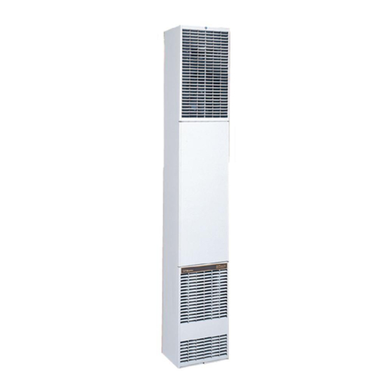
COUNTERFLOW
TOP VENT
GAS WALL FURNACES
READ THIS OWNERS
MANUAL
CAREFULLY
BEFORE YOU INSTALL
YOUR NEW WILLIAMS
WALL FURNACE
WARNING:
If the
information
in this
manual is not followed exactly, a fire or ex-
plosion
may
result
causing
property
damage,
personal
injury or loss of life.
--
Do not store or use gasoline
or other
flammable
vapors
and liquids
in the
vicinity
of this or any other appliance.
WHAT TO DO IF YOU SMELL
GAS
• Open all windows.
• Do not try to light any appliance.
• Do not touch any electrical switch; do
not use any phone in your building.
• Extinguish
any open flame.
• Immediately
call your gas supplier
from a neighbor's
phone. Follow the
gas supplier's
instructions.
• If you cannot reach your gas supplier,
call the fire department.
Installation
and service
must be per-
formed
by a qualified
installer, service
agency
or the gas supplier.
WARNING:
Improper
installation,
adjust-
ment, alteration,
service
or maintenance
can cause
injury
or property
damage.
Refer to this manual.
For assistance
or
additional
information
consult a qualified
installer,
service
agency
or
the
gas
supplier.
WARNING:
Do not install any of these fur- I
naces
(Natural
or L.R
Gas)
in mobile
I
homes,
trailers,
or recreational
vehicles.
ALL
MODELS
ARE
CERTIFIED
FOR
USE
IN
CANADA
EXCEPT
6508731
AND 6508732.
Williams Furnace Co., 225 Acacia St., Colton, CA 92324, USA
PRINTED
IN U.S.A
6/98
P321005
Advertisement
Table of Contents
Troubleshooting

Related Manuals for Williams 5508332


Summary of Contents for Williams 5508332
- Page 1 Do not install any of these fur- I naces (Natural or L.R Gas) in mobile homes, trailers, or recreational vehicles. MODELS CERTIFIED CANADA EXCEPT 6508731 AND 6508732. Williams Furnace Co., 225 Acacia St., Colton, CA 92324, USA PRINTED IN U.S.A 6/98 P321005...
-
Page 2: Table Of Contents
Surface Mount Installation ....12-13 How To Order Repair Parts ..... Back Cover Your Warranty The Manufacturer, Williams Furnace Co., warrants this wall furnace or heater to the original purchaser under the following conditions: LIMITED ONE-YEAR WARRANTY 1. Any part thereof which proves to be defective in material or workmanship within one year from date of original... -
Page 3: Introduction
The combustion gases are discharged center to center. through the roof within a listed vent pipe Vent piping and exhaust are not part of the Williams fur- The furnace heat exchanger is built of heavy gauge steel nace package and must be purchased separately. -
Page 4: Safety Rules
Safety Rules WARNING For L.IR gas, the minimum inlet gas supply pressure for the purpose of input adjustment is 11" water col- READ THESE RULES AND THE INSTRUCTIONS umn. The maximum inlet gas supply pressure is 13" CAREFULLY. FAILURE FOLLOW THESE water column. -
Page 5: Unpack Your Furnace
Unpack Your Furnace The furnace is shipped in one carton containing the fur- nace, installation instruction booklet and hardware bag. 1. Lay carton horizontally. Remove top trim cover from its packing. Remove thumb screw at top of furnace, raise top front panel 1/2 inch and remove panel from cabinet. -
Page 6: Installing Your Wall Furnace
Installing Your Wall Furnace IMPORTANT The following steps are needed for proper installation and safe operation of your furnace. If you have any doubts as For satisfactory and trouble-free operation, be sure to: to any requirements, always consult your local Heating or 1. -
Page 7: Combustion And Ventilation Air
Locating Wall Furnace & Thermostat (Con't) Choose a location for the thermostat about 5 feet above the floor on an inside wall. The thermostat wire supplied with your furnace is 20 feet long, which should be enough to run up through the attic so the thermostat can be a max- I_llM imum of 16 feet from the furnace measured in a straight line, or approximately... - Page 8 Combustion & Ventilation Air (cont.) AIR REQUIREMENTS tion air. The doors should not fit tight. The cracks around windows should not be caulked or weather The requirements for providing air for combustion stripped. ventilation are listed in the National Fuel Gas Code NFPA 54/ANSI Z223.1 (in Canada: CAN/CGA B149).
- Page 9 Combustion & Ventilation Air (cont.) WARNING, provided with free air for proper combustion and ventila- tion of flue gases by one of the following methods. DANGER OF PROPERTY DAMAGE, A. All Air From Inside Building: BODILY INJURY OR DEATH DRAFT HOOD SPILLAGE, WITH UNOBSTRUCTED If the confined space adjoins an unconfined space as VENTS, INDICATES THAT ADDITIONAL AIR MUST...
- Page 10 Combustion & Ventilation Air (cont.) If horizontal ducts are used, the free area of each open- ing must be at least 1 square inch per 2000 Btuh com- bined input of appliances in area. GRILLES CONNECTING ROOMS TO MAKE UNCONFINED SPACE *Openings for inlet or outlet air should not be made into attic area if attic is equipped with a thermostat controlled...
- Page 11 Recessed Mount Installation (cont.) GAS SUPPLY OPENING See Fig. 10. A hole must be drilled for the gas line supply. MODELS: 5008731; 5008732 Decide whether the gas line will come through the floor Locate header plate between wall studs at 821/2 inches or wall stud.
- Page 12 Recessed Mount Installation (cont.) CAUTION CLOSE OFF STUD SPACE (If Required) Do not run wire behind flanges of header plate or in any location where it might be damaged. Avoid splicing thermostat wire unless the spliced wires are PLA'I_ properly cleaned, soldered and taped. I_]b-I1NG b-lUD NEW S'IUD...
- Page 13 Surface Mount Installation (cont.) CAUTION At selected location, drill a 1 inch hole for 115V power supply and a 1/2 inch hole for the thermostat cable. while making any alternate hole. e careful not to damage any furnace components Run wiring through holes to above furnace top leaving enough excess wire to make electrical connections after mounting furnace.
- Page 14 General Vent Installation (cont.) INSTALL CEILING PLATE SPACERS Discard the three (3) square gaskets, as they are not used when furnace is surface mounted. (SURFACE MOUNT) Slide header plate over the furnace flue extension with the Refer to Fig. 16. junction box entering the opening in top of furnace.
- Page 15 General Vent Installation (cont.) Lower vent pipe to the hold-down plate. Push the vent TYPICAL VENT INSTALLATION pipe into the hold-down plate until it is completely seated. (Hold-down cleats will engage the groove in the vent pipe.) Vl_IT CAP "rOBE AMINo OF2 FT. HIGHER THAN ANY pOINT _ 10 FT.
- Page 16 Fasten furnace to floor through holes provided in furnace bottom. If you have concrete flooring, use an alternate fastening method. See Fig. 20. If burner and control assembly were removed, replace them reversing "DISCONNECT WIRING" WILLIAMS IGNITION CONTROL "REMOVE BURNER AND CONTROLS" sections on PART NUMBER P321910 page 15.
- Page 17 Mounting Your Furnace (cont.) IMPORTANT over the back flange of furnace top and screwing to wall. See Fig. 20, page 16. TO PREVENT DAMAGE TO WIRING, MAKE SURE NOT TO PINCH THE WIRES BETWEEN FURNACE FASTEN FURNACE TOP (RECESSED MOUNTING) COMPONENTS.
- Page 18 Gas Supply and Piping (cont.) CHECKING THE GAS PIPING Test all piping for leaks. When checking gas piping to the PROPER PIPING PRACTICE furnace with gas pressure less than 1/2 PSI, shut off 2 IMPERFECT CONTRO MODERATE AMOUNT DOPE manual gas valve for the furnace. If gas piping is to be checked with the pressure at or above 1/2 PSI, the fur- nace and manual shut off valve must be disconnected dur- THREADS...
- Page 19 WARNING LOW VOLTAGE CONNECTIONS DANGER OF PROPERTY DAMAGE, BODILY INJURY OR DEATH. CAUTION TURN OFF ELECTRIC POWER AT FUSE BOX The Heat Anticipator WILL BURN OUT if 24 volts are OR SERVICE PANEL BEFORE MAKING applied directly to thermostat by shorting out the gas ELECTRICAL CONNECTIONS.
- Page 20 Thermostat Installation 1. If an old thermostat is being replaced and is in a ROUTE THERMOSTAT CABLE satisfactory location and the wiring appears to be in good condition, use existing wiring. If in doubt, use new wire. 2. If a new location is chosen or if this is a new installa- tion, thermostat cable must first be run to the location selected.
- Page 21 Thermostat Installation (ton't) NOTE Refer to installation instructions packed in the thermostat carton if you have any doubt about the above procedures. MV "--X.-_J_ -LONGER When all is adjusted properly, the furnace burner should HEAT AN 0,P TOR .---,.- 1.0 .-'-- CYCLE shut off slightly before the desired room temperature is reached.
- Page 22 Optional Accessory Installation (cont.) INSTALL PLASTERGROUNDS Install Plastergrounds as shown in Figs. 29 and 30. Flanges of Plastergrounds extend the normal thickness - PLASTER GROUND of plaster. If "DRYWALL" or other thin material, flanges must be trimmed off flush with wall surface. REAR PLASTER GROUND CENTERS EXACTLY ON THE BACK OF THE HEATER...
- Page 23 Optional Accessory Installation (cont.) Fasten Boot to Inner Liner with screws provided. NOTE Using holes in grille as a template, drill two (2) #33 holes Quarter-round wood molding may be used for trim if in out casing and fasten securely with screws provided, desired, which may be painted to match the wall.
- Page 24 Start-Up Procedure Start furnace using the procedures in section manometer having a scale range from 0 to 12 inches of OPERATING YOUR FURNACE. water should be used for this measurement. The manifold pressure must be measured with the burner and pilot WARNING operating.
- Page 25 NOTE: LIGHT PILOT WITH GAS CONTROL VALVE KNOB IN "ON" POSITION. FLASHBACK COULD OCCUR. For models equipped with WILLIAMS gas valve P322041 or P322042 refer to this sheet and sheet 26 for "SAFETY & LIGHTING INSTRUCTION" and "TURN GAS OFF TO APPLIANCE."...
- Page 26 FOR YOUR SAFETY, READ BEFORE LIGHTING I WARNING: If you do not follow these instructions exactly, a fire or explosion may result causing property damage, personal injury or loss of life, This appliance has a pilot which must be lighted •...
- Page 27 FOR YOUR SAFETY, READ BEFORE LIGHTING I WARNING: If you do not follow these instructions exactly, a fire or explosion may result causing property damage, personal injury or loss of life. This appliance has a pilot which must be lighted •...
- Page 28 NOTE: PROTECT YOUR EYES. NEVER ATTEMPT TO LIGHT PILOT WITH GAS CONTROL VALVE KNOB For models equipped with WILLIAMS gas valve P322043 IN "ON" POSITION. FLASHBACK COULD OCCUR. or P322044 refer to this sheet and sheet 29 for "SAFETY & LIGHTING INSTRUCTION"...
- Page 29 FOR YOUR SAFETY, READ BEFORE LIGHTING WARNING: If you do not follow these instructions exactly, a fire or explosion may result causing property damage, personal injury or loss of life. • If you cannot reach your gas supplier, call the fire This appliance is equipped with an ignition...
- Page 30 FOR YOUR SAFETY, READ BEFORE LIGHTING I WARNING: If you do not follow these instructions exactly, a fire or explosion may result causing property damage, personal injury or loss of life. This appliance is equipped with an ignition device which •...
- Page 31 How To Care For Your Furnace PILOT BURNER WARNING DANGER OF BODILY INJURY OR DEATH Light pilot using instructions in OPERATING YOUR FURNACE (on pages 25 through 30, depending on your TURN ELECTRIC POWER SUPPLY model). Leave thermostat at lowest setting. DISCONNECT SWITCH, FUSE BOX OR SERVICE PANEL BEFORE...
- Page 32 How To Care For Your Furnace (Con't) BURNER CLEANING Refer to "Mounting Your Furnace" section (pages 15, 16 and 17). Check burner. If cleaning is required, contact a qualified service technician to clean and service burner. Check the spark gap. It must be carefully adjusted to specifications as illustrated (Fig.
- Page 33 Troubleshooting Chart FOR MODELS: 3508731; 3508732; 5008731; 5008732; 6508731; 6508732 SYMPTOM CORRECTIVE ACTION POSSIBLE CAUSE(S) a. Thermocouple producing insuffi- Check pilotflame -- must impinge onthermocouple.Pilotflame 1. Pilot will not stay lit after following lighting cient millivoltage. may be low or blowing (high)causing safetyto drop out. Pilo_orifice instructions.
- Page 34 Troubleshooting Chart FOR MODELS: 3508731; 3508732; 5008731; 5008732; 6508731; 6508732 CORRECTIVE ACTION SYMPTOM POSSIBLE CAUSE(S) 3. Burner comes "ON" but c, Defective motor (2-speed). Jumperacross fan switch,turnelectric powerON, motor should goes OFF before blower rotate. A 2-speedmotor is used-- jumper from "brown" terminal on fan switchto #2 (red)terminalon selector switch, motorshould turns ON.
- Page 35 Troubleshooting Chart FOR MODELS: 3508331; 3508332; 5508331; 5508332 CORRECTIVE ACTION SYMPTOM POSSIBLE CAUSE(S) 1. No spark-- no pilotgas. a. No main powe_ a.-e. Perform normalsystemchecks of main power, transformer, ther- mostat, limit switch, and replace faulty component. Faulty transformer. With power ON, turn thermostatto the lowestsetting, wait 10 Faulty thermostat.
- Page 36 Troubleshooting Chart FOR MODELS: 3508331; 3508332; 5508331; 5508332 SYMPTOM CORRECTIVE ACTION POSSIBLE CAUSE(S) See 3a. 4. Pilotlit,but mainburner a. Faultyignitioncontrol. won't come ON. See if. b. Faultywiring. Low pilot flame. NOTE:Waitat least 90 secondsafter pilotlightsbefore doing the check out procedures for problem number 4. With thermostatON, be sure that the pilot and sensor are prop- erly aligned so that the pilot flame impinges the top 3/4 inch of the sensoi_Be sure that the sensor is pushed all the way into pilot...
- Page 37 Wiring Diagrams FOR MODELS: FOR MODEL_ 5508331 5508332 3508331 3508332 FOR 55M B.T.U. FOR 35M B.T.U. FAN TYPE VENTED WALL FURNACE FAN TYPE VENTED WALL FURNACE WITH INTERMITTENT IGNITION CONTROL SYSTEM WITH INTERMITTENT IGNITION CONTROL SYSTEM • 115V BOHZ 115V 80HZ NEUT SWITCH...
- Page 38 Wiring Diagrams FOR MODELS: {:'OR MODELS: 5008731 5008732 3508731 3508732 6508731 6508732 FOR 50M AND 65M B.T.U. FOR 35M B.T.U. FAN TYPE VENTED WALL FURNACE FAN TYPE VENTED WALL FURNACE WITH CONTINUOUS PILOT CONTROL SYSTEM WITH CONTINUOUS PILOT CONTROL SYSTEM "I.
- Page 39 Williams Top Vent Gas-Fired Wall Furnace REPAIR PARTS FOR MODELS 3508331; 3508332; 3508731 and 3508732 CABINET and BODY ASSEMBLY 18 19 USE ONLY MANUFACTURER'S AUTHORIZED PARTS FOR PARTS LIST SEE PAGES 41 AND 42. --39--...
- Page 40 Williams Top Vent Gas-Fired Wall Furnace CONTROL ASSEMBLY FOR MODELS 3508731 3508732 FOR PARTS LISTING PAGE 42 USE ONLY MANUFACTURER'S AUTHORIZED PARTS CONTROL ASSEMBLY FOR MODELS- 3508331 3508332 FOR PARTS LISTING PAGE 42 --40--...
- Page 41 Williams Top Vent Gas-Fired Wall Furnace REPLACEMENT PARTS LIST FOR MODELS 3508331; 3508332; 3508731 and 3508732 PART NO. FOR MODEL: REF. DESCRIPTION 3508332 3508731 35O8331 3508732 12C10 12C10 12C10 Outer Casing, Less Front Panel 12C10 tnner Liner 12B15 12B15 12B15...
- Page 42 REPLACEMENT PARTS MODELS 3508531; 3508332; 3508731 5508752 PART NO. FOR MODEL: REF. DESCRIPTION 3508331 3508332 3508731 3508732 P322041 Valve, WILLIAMS Nat. P322043 Valve, WILLIAMS L.P.G. P322044 P322042 Manifold 12A01 12A01 12A01 12A01 P090500 P090500 Orifce Fitting, Specify Model & Gas...
- Page 43 Williams Top Vent Gas-Fired Wall Furnace REPAIR PARTS FOR MODELS 5008731; 5008732; 5508331; 5508332; 6508731 and 6508732 CABINET and BODY ASSEMBLY 1 • USE ONLY MANUFACTURER'S AUTHORIZED PARTS FOR PARTS LIST SEE PAGES 45 AND 46. --43--...
- Page 44 Williams Top Vent Gas-Fired Wall Furnace CONTROL ASSEMBLY FOR MODELS 5008731 5008732 6508731 6508732 FOR PARTS LISTING PAGE 46 ONLY MANUFACTURER'S AUTHORIZED PARTS CONTROL ASSEMBLY FOR MODELS- 5508331 5508332 PARTS LISTING SEE PAGE 46 --441...
- Page 45 Williams Top Vent Gas-Fired Wail Furnace REPLACEMENT P ARTSFOR MODELS5008731 5008732; 5508331; 5508332; 6508731 AND 6508732 REF. PART NO. FOR MODEL: DESCRIPTION 5008731 5008732 5508331 5508332 6508731 6508732 7055-4 7055_t 7C55-3 7C55-3 7C55-3 7C55-3 Outer Casing, Less Front Panel Inner Liner...
- Page 46 P090500 P09050C P026200 P026200 P026200 P026200 P026200 Locknut (2 Req.) P02620C Valve, _LLIAMS Nat. P32204-1 P322043 P322041 P32204-2 P322044- Valve, WILLIAMS L.P.O. P32204-2 Thermostat P322017 P322017 P322017 P322017 P322017 P322017 Junction Block Thermocouple P321828 P321828 P321828 P321828 Flame Sensor P271100 P271100 Pilot, Cast Iron Burner, Robertshow LP.G.
- Page 47 Notes...
- Page 48 1. MODEL NUMBER The Model Number of your Williams wall furnace will be 2 MFG. DATE CODE found on the rating plate near gas valve, inside control 3 PART NUMBER compartment. 4 PART DESCRIPTION...