Table of Contents
Advertisement
OWNER'S MANUAL
INSTALLATION INSTRUCTION
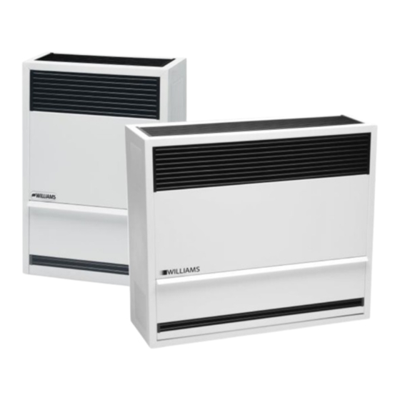
DIRECT-VENT
WALL FURNACE
MODELS:
1403822; 1413822; 1433822; 1453822;
2203822; 2213822; 2233822; 2253822;
3003822; 3013822; 3033822; 3053822
NATURAL GAS ONLY
MODELS:
1403821; 1413821; 1433821; 1453821;
2203821; 2213821; 2233821; 2253821;
3003821; 3013821; 3033821; 3053821
PROPANE GAS ONLY
SAVE THIS MANUAL FOR FUTURE REFERENCE.
WARNING:
This product can expose you to chemicals
including epichiorohydrin which is known to the State of
California to cause cancer and birth defects and/or other
reproductive harm. For more information go to
www.p65warnings.ca.gov.
WARNING:
Improper installation, adjustment, alteration,
service or maintenance can cause injury or property damage.
Refer to this manual for proper installation. For assistance or
for additional information consult a qualified installer, service
agency or the gas supplier.
250 WEST LAUREL STREET, COLTON, CA 92324 U.S.A.
14,000 BTU/hr.
22,000 & 30,000 BTU/hr.
READ THIS OWNER'S MANUAL CAREFULLY BEFORE YOU
INSTALL YOUR NEW WILLIAMS WALL FURNACE.
If the information in these
WARNING:
instructions is not followed exactly, a fire or
explosion may result causing property damage,
personal injury or loss of life.
– Do not store or use gasoline or other flammable
vapors and liquids in the vicinity of this or any
other appliance.
– WHAT TO DO IF YOU SMELL GAS:
• Open all windows
• Do not try to light any appliance.
• Do not touch any electrical switch.
• Do not use any phone or cell phone in your
building.
• Extinguish any open flame.
• Immediately call your gas supplier from a
neighbor's phone. Follow the gas supplier's
instructions.
• If you cannot reach your gas supplier, call the
fire department.
–
Installation and service must be performed by a
qualified installer, service agency or the gas
supplier.
Advertisement
Table of Contents

Related Manuals for Williams 1403821


Summary of Contents for Williams 1403821
- Page 1 14,000 BTU/hr. 22,000 & 30,000 BTU/hr. READ THIS OWNER’S MANUAL CAREFULLY BEFORE YOU SAVE THIS MANUAL FOR FUTURE REFERENCE. INSTALL YOUR NEW WILLIAMS WALL FURNACE. If the information in these WARNING: instructions is not followed exactly, a fire or explosion may result causing property damage, personal injury or loss of life.
-
Page 2: Your Williams Warranty
Warranty The manufacturer, Williams Furnace Co., warrants this wall furnace or heater to the original purchaser under the following conditions: LIMITED ONE-YEAR WARRANTY 1. Any part thereof which proves to be defective in material or workmanship within one year from date of original purchase for use will be repaired or replaced at the Manufacturer’s option, FOB, to its factory. -
Page 3: Table Of Contents
Table of Contents Your Williams Warranty ..............2 Installation Record ................. 2 Table of Contents ................3 Safety Rules .................. 4 Introduction ..................5 Description ..................5 Tools Needed ................5 Materials ..................5 Helpful Installation Information ............5 Optional Accessories ..............5 Installation ................ -
Page 4: Safety Rules
Safety Rules BE SURE to provide for adequate combustion and ventilation air. The flow of this air to the furnace must not WARNING: READ THESE RULES AND THE be blocked. INSTRUCTIONS CAREFULLY. FAILURE 10. NEVER vent flue gases into another room, a fireplace or FOLLOW THESE RULES AND INSTRUCTIONS any space inside a building. -
Page 5: Introduction
Introduction – 5 Introduction Please read our instructions before you install and use your furnace. This will help you obtain the full value from this furnace. It will also help you avoid any needless service costs if the problem is found within this instruction manual. Always consult your local heating or plumbing inspector, building department or electric utility company regarding regulations, codes or ordinances which apply to the installation of a Direct-Vent Wall Furnace. -
Page 6: Installation
Installation Locating Wall Furnace Choose a location for the thermostat (optional) about 5-feet Consider the following points before attempting to install the above floor on an inside wall. The thermostat wire supplied furnace. with your furnace is 20-feet long, which should be enough to All Models run up through the attic so the thermostat can be a maximum 1. - Page 7 Installation Drill a 1/4 inch hole in the wall at the vent opening center mark FIGURE 2 all the way through to the outside. Cut the 9-1/4 inch diameter hole through the inside wall. Using the 1/4 inch hole as center, cut a matching hole in the outside wall.
- Page 8 Installation If the wall surface is not flat (shiplapped siding, etc.) or less FIGURE 4 than 5 inches thick, use a Thin Wall Collar Kit (9307) or, build up a flat surface with wood strips. Do not tilt or bend the cap to fit uneven surfaces.
-
Page 9: Thermostat Installation
Installation Thermostat Installation (Sold Separately) Wall Mounting Cabinet Mounting 1. Use Williams thermostat P322016 millivolt 1. Locate the knockout on the right side of the furnace to thermostat. mount the thermostat. Remove the knockout by tapping it 2. If an existing thermostat is being replaced and is in a lightly with a screwdriver. - Page 10 Installation Thermostat Mounting FIGURE 9 1. To remove the thermostat cover, grasp cover and squeeze both sides firmly, then lift to remove cover. Carefully remove and discard the packing tab protecting the switch contacts. 2. Connect thermostat wires to the terminal screws on the front of thermostat base.
-
Page 11: Cabinet Installation
Installation Cabinet Installation 14038 Series: Set the cabinet over the furnace body, dropping the rear top 22038 / 30038 Series: flange between the support legs and wall. Open the cabinet Set the cabinet over the furnace body, dropping the rear top door and attach the cabinet to the inner casing with two (2) flange into the slot in top of the spacer plate and into the slots sheet metal screws. - Page 12 Installation 2. Do not thread the pipe too far. Distortion or malfunction may Orifice Sizes result from excess pipe within the control valve. Apply a The efficiency rating of these appliances is a product thermal moderate amount of good quality dope to the pipe threads efficiency rating determined under continuous operating only.
- Page 13 Installation FIGURE 13 FIGURE 14 Checking the Gas Piping Test all piping for leaks. When checking gas piping to the Gas Pipe Sizes furnace with gas pressure at less than 1/2 PSI, shut off manual Natural Gas gas valve to the furnace. If the gas piping is to be checked with Pipe Capacity –...
-
Page 14: Operating Your Furnace
Operating Your Furnace The furnace operates in the following sequence: Input and output ratings shown on the rating plate, located in burner compartment, must not be exceeded. 1. The thermostat turns on the main burner. KEEP BURNER CONTROL 2. Heat builds up in the furnace and starts the fan (if IMPORTANT: COMPARTMENT CLEAN. -
Page 15: Operating Instructions
Operating Your Furnace Operating Instructions 1. STOP! Read the safety information above. 2. Set the thermostat to lowest setting. 3. If applicable, tum off all electric power to the appliance. 4. Open the control access panel. 5. Push in the gas control knob slightly and turn it clockwise to “OFF”. - Page 16 Operating Your Furnace pressure. Increase or decrease the pilot flame to obtain proper setting. Type of Gas Manifold Pressure, In W.C. Natural FIGURE 15 L.P. The rated input will be obtained on 2,500 Btu of propane at 10 inches manifold pressure with factory-sized orifices. If L.P. Gas having a different value is supplied, orifices must be changed by a qualified installer before the furnace is operated.
-
Page 17: How To Care For Your Furnace
How to Care for Your Furnace Abnormal Appearance Lazy Flame: Vent System Long soft yellow cones moving around in the combustion Check the vent cap and tubes to be sure there are no blocked chamber lifting from ports (insufficient air). inlet air or flue openings. -
Page 18: Installations In The State Of Massachusetts
Installations in the State of Massachusetts All installations in the State of Massachusetts must use the following requirements when installing, maintaining or operating direct-vent propane or natural gas-fired space furnaces. For direct-vent appliances, mechanical-vent heating appliances or domestic hot water equipment, where the bottom of the vent terminal and the air intake is installed below four feet above grade the following requirements must be satisfied: 1. -
Page 19: Blower Accessory 2302 And 2303
Blower Accessory 2302 and 2303 This accessory can be operated using the factory equipped three-prong (grounding) plug and cord or may be field wired. See field wiring installation instructions below. When using the plug and cord, for your protection against shock hazard, it must be plugged directly into a properly grounded three- prong receptacle. - Page 20 Blower Accessory 2302 and 2303 Note: If any of the original wire as supplied with the appliance has to be replaced, use only 18 Ga., 4/64 insulation, 105 C AWM wire or its equivalent 115V, 60Hz, - less than 3 amps. Total electrical load less than 3 AMPS Figure 3...
- Page 21 Blower Accessory 2302 and 2303 Replacement Parts List Model 2302 Ref. Number Part Number Description 6A24 Switch Box Bracket 6B33 Switch Box Fan Switch (Pull Chain) P321017 P332490 Automatic Fan Switch 6A23 Switch Box Cover P130600 Motor 6A93 Motor Support P128400 Vibration Isolator (2 Required) P130700...
-
Page 22: Replacement Parts List
Replacement Parts List 1403821 1403822 1413821 1413822 Ref. Number Description 1433821 1433822 1453821 1453822 Face Panel 4309 4309 Combustion Chamber Shield 8A72 8A72 Combustion Chamber 6303 6303 Flue Tube Gasket (2 Required) P147001/2 P147001/2 Inner Casing 8B62 8B62 Air Inlet Gasket... - Page 23 Replacement Parts List 2203821 2203822 3003821 3003822 2213821 2213822 3013821 3013822 Ref. Number Description 2233821 2233822 3033821 3033822 2253821 2253822 3053821 3053821 Face Panel 4313 4313 4313 4313 Combustion Chamber Shield 6B149 6B149 6B149 6B149 Flue Tube Gasket (2 Required) P147001 P147001 P147001...
- Page 24 Replacement Parts List 1403821 1403822 1413821 1413822 Ref. Number Description 1433821 1433822 1453821 1453822 Burner P168400 P168400 Control Door with P500677 Gasket 8A103 8A103 Gas Valve P295201A P295200A Manifold with P147200 Gasket P323659 P323659 Burner Orifice (Sea Level) P090556 P090550...
-
Page 25: Troubleshooting
Troubleshooting SYMPTOM POSSIBLE CAUSE CORRECTIVE ACTION 1. Pilot will not stay lit A. Generator producing insufficient Check the pilot flame. It must impinge on the after carefully millivolts. generator. Be sure the generator is fully following lighting inserted in the bracket. Make sure the pilot instructions. - Page 26 Troubleshooting SYMPTOM POSSIBLE CAUSE CORRECTIVE ACTION thermostat. Relocate the thermostat. C. Defective thermostat. Check the thermostat calibration or replace. D. Dirt under the valve seat or valve stuck Replace the valve. open. 7. Pilot outage A. Pilot flame may be low or blowing Adjust pilot flame.
-
Page 27: Service Record
Service Record Date Maintenance Performed Components Required... -
Page 28: Hints And Information
2. Mfg. Date code 3. Part number 4. Part description All parts listed herein may be ordered from your equipment supplier. The model number of your Williams wall furnace will be found on the name plate. 250 West Laurel Street, Colton, CA 92324...