Table of Contents
Advertisement
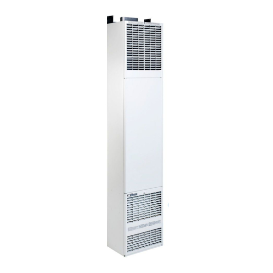
Owner's Manual
Williams Furnace Co. 250 West Laurel Street Colton, California 92324 U.S.A.
S
Forsaire
Top-Vent Gas Wall
Furnaces
Model Numbers:
3508232; 3518232; 3538232; 3558232; 3508632; 3518632;
3538632; 3558632; 5008632; 5018632; 5038632; 5058632;
5508232; 5518232; 5538232; 5558232; 6508632; 6518632;
6538632; 6558632
FOR USE WITH NATURAL GAS ONLY
Model Numbers:
3508231; 3518231; 3538231; 3558231; 3508631; 3518631;
3538631; 3558631; 5008631; 5018631; 5038631; 5058631;
5508231; 5518231; 5538231; 5558231; 6508631; 6518631;
6538631; 6558631
FOR USE WITH PROPANE GAS ONLY
READ THIS OWNER'S MANUAL CAREFULLY BEFORE YOU
INSTALL YOUR NEW WILLIAMS WALL FURNACE.
WARNING:
If
the
instructions is not followed exactly, a fire or
explosion
may
damage, personal injury or loss of life.
Do not store or use gasoline or other
flammable vapors and liquids in the vicinity
of this or any other appliance.
WHAT TO DO IF YOU SMELL GAS:
Open all windows.
Do not try to light any appliance.
Do not touch any electrical switch; do not
use any phone or cell phone in your
building.
Extinguish any open flame.
Immediately call your gas supplier from
a neighbor's phone. Follow the gas
supplier's instructions.
If you cannot reach the gas supplier,
call the fire department.
Installation and service must be performed
by a qualified installer, service agency or
the gas supplier.
WARNING: Improper installation, adjustment, alteration,
service or maintenance can cause injury or property
damage. Refer to this manual. For assistance or for
additional information consult a qualified installer,
service agency or the gas supplier.
ave this manual for future reference.
Counterflow
information
in
these
result
causing
property
Advertisement
Table of Contents

Related Manuals for Williams 3508232


Summary of Contents for Williams 3508232
- Page 1 Refer to this manual. For assistance or for additional information consult a qualified installer, service agency or the gas supplier. Williams Furnace Co. 250 West Laurel Street Colton, California 92324 U.S.A.
-
Page 2: Your Williams Warranty
Warranty & Installation Record – 2 Warranty The manufacturer, Williams Furnace Co., warrants this wall furnace or heater to the original purchaser under the following conditions: LIMITED ONE-YEAR WARRANTY 1. Any part thereof which proves to be defective in material or workmanship within one year from date of original purchase for use will be replaced at the Manufacturer’s option, FOB to its factory. -
Page 3: Table Of Contents
Installation Record ................. 2 Table of Contents ................3 Unpack the furnace ............... 6 Safety Rules .................. 4 Learn how to unpack the new Williams Furnace and verify that all its parts are in working order. Introduction ..................5 Basic Description ................5 Install the furnace.............. -
Page 4: Safety Rules
Safety Rules Install the furnace vent directly to the outdoors so that harmful combustible flue gases will not collect inside the WARNING: Read these rules and the instructions building. Follow the venting instructions for your type of carefully. Failure to follow these rules and installation exactly. -
Page 5: Introduction
Introduction – 5 Introduction Basic Description The following steps are all needed for proper installation and DO NOT convert the furnace from natural gas to L.P. gas or from L.P. gas to natural gas without the proper manufacturer’s gas safe operation of your furnace. If you have any doubts as to any requirements, check with local authorities. -
Page 6: Optional Accessories
Introduction Optional Accessories OVAL VENT KIT 9901 DIFFUSER GRILLE KITS 6703 & 6704 This U.L. listed B/W vent kit contains 4 feet of oval double walled Let’s you route some heated air in a two-way direction. Kit 6704 vent pipe, plate spacers and starter or hold-down plate that starts for one-way direction. -
Page 7: Installing Your Wall Furnace
Installing Your Furnace 1. Locate the furnace properly within the space to be heated. The following steps are needed for proper installation and safe operation of your furnace. If you have any doubts as to any 2. Install the furnace in accordance with local codes or requirements, always consult your local Heating or Plumbing ordinances and instructions provided. -
Page 8: Combustion And Ventilation Air
Installing Your Furnace FIGURE 3 Minimum Clearances With standard furnace discharge outlet, do not install closer than 4 inches to intersecting wall. Choose a location for the thermostat about 5 feet above the floor on an inside wall. The thermostat wire supplied with your furnace is 20 feet long, which should be enough to run up through the attic so the thermostat can be a maximum of 16 feet from the furnace measured in a straight line, or approximately 12 feet from the... -
Page 9: Installing Your Furnace
Installing Your Furnace AIR REQUIREMENTS FIGURE 4 Draft Hood Spillage The requirements for providing air for combustion and ventilation are listed in the National Fuel Gas Code NFPA 54/ANSI Z223.1 (in Canada: CAN/CGA B149). Most homes will require that outside air be supplied to the heated area by means of ventilation grilles or ducts connecting directly to the outside or spaces open to the outdoors such as attic or crawl space. - Page 10 Installing Your Furnace within 12 inches of the bottom of the room connecting directly to 4. Spillage means air starvation and a fresh air duct or air unconfined space. Each opening must have a free area of at least intakes must be installed to provide air directly to the 100 square inches or 1 square inch per 1000 Btu/hr.
-
Page 11: Recessed Mount Installation
Installing Your Furnace FIGURE 7 Grilles Connecting Rooms to FIGURE 8 Air from Outdoors or Crawl Make Unconfined space Space Openings for inlet or outlet air should not be made into attic area if attic is equipped with a thermostat controlled power vent. FIGURE 9 Free Area Btu/hr./Input... - Page 12 Installing Your Furnace Locate and drill one (1) 1-1/2 inch hole at selected locations as MODELS: 3508231; 3508232; 3508631; 3508632 shown on Page 12, Fig. 11 and Page 13, Fig. 13 or Page 14, Fig. Locate header plate between wall studs at 74 inches from finished floor and nail into position with end flanges pointing up.
-
Page 13: Surface Mount Installation
MODELS : 5508231; 5508232 spliced wires are properly cleaned, soldered and 6508631; 6508632 taped. MODELS : 5008631; 5008632 MODELS : 3508231; 3508232 3508631; 3508632 Surface Mount Installation FIND THE STUDS AND CEILING JOISTS ELECTRICAL SUPPLY ROUGH-IN (See CAUTION on page 7) The electrical supply openings must be made in the wall or floor Find two studs at spot where furnace is to be placed. -
Page 14: General Vent Installation
Installing Your Furnace NOTE If you decide to route gas line through right side of furnace, simply remove the knock-out provided in furnace side. NOTES If a pre-existing gas piping stub location is not compatible with hole or knock-out provided in furnace, you may make an alternate entry hole in furnace back wall per Fig. - Page 15 Installing Your Furnace ALL MODELS Nail the ceiling plate spacers either across or in between the cut out section of ceiling plate. If nailed between, ends must be bent ATTACH HOLD-DOWN PLATE at 90 degrees. (RECESSED MOUNT) NOTE Header plate should already be attached to wall studs. See ATTACH HEADER PLATE, on Page 11 and 12.
-
Page 16: Mounting Your Furnace
DISCONNECT WIRING REMOVE BURNER AND CONTROLS MODELS: 3508231; 3508232; 3508631; 3508632 MODELS: 3508231; 3508232; 5508231; 5508232 Locate the burner and screws that secure it. Remove the two (2) Remove the screws holding the ignition control unit and cover to screws (one from each end). - Page 17 Installing Your Furnace PART NUMBER P321900 ALL OTHER MODELS Locate the burner and hex nuts that secure it. Remove the two (2) hex nuts (one from each end). Flip up the wire hinges. Lift one end of burner at a time until free. Remove burner and controls from the compartment.
-
Page 18: Gas Supply And Piping
Installing Your Furnace Gas Supply and Piping Gas control valve, within the furnace, is shipped with a seal over the gas inlet tapping. Do not remove seal until ready to connect piping. FIGURE 21 WARNING: Danger of property damage, bodily injury or death. -
Page 19: Electrical Wiring
Installing Your Furnace The following rules apply: disconnected during testing. (SEE WARNING.) Apply soap solution to each joint. Bubbles forming indicate a leak. Correct 1. Use new, properly reamed pipe free from metal chips and even the slightest leak at once. debris such as steel or black iron pipe. -
Page 20: Thermostat Installation
Installing Your Furnace Thermostat Installation 1. If an old thermostat is being replaced and is in a satisfactory FIGURE 24 Route Thermostat Cable location and the wiring appears to be in good condition, use existing wiring. If in doubt, use new wire. 2. -
Page 21: Start Up Procedure
Installing Your Furnace Start-Up Procedure CHECK THE MANIFOLD GAS PRESSURE Start the furnace using the procedures in section OPERATING YOUR FURNACE. A tapped opening is provided in the gas valve to facilitate measuring the manifold gas pressure. A "U Tube" manometer having a scale range from 0 to 12-inches of water should be used WARNING: Danger of bodily injury or death. -
Page 22: Operating Your Furnace
NOTE: NOTE Models 3508631; 3508632 are equipped with a single speed fan. Models 3508231; 3508232 are equipped with a single speed fan. TWO-SPEED FAN OPERATION MODELS: 5508231; 5508232 TWO-SPEED FAN OPERATION Blower will first operate at low speed then shift to high speed as MODELS: 5008631;... - Page 23 Care – 23 Operating Your Furnace FOR YOUR SAFETY, READ BEFORE LIGHTING • If you cannot reach your gas supplier, call the fire department. WARNING: If you do not follow these instructions Use only your hand to push in or turn the gas control knob. exactly, a fire or explosion may result causing Never use tools.
-
Page 24: How To Care For Your Furnace
Caring for Your Furnace How To Care For Your Furnace PILOT BURNER WARNING: Danger of bodily injury or death. Turn off electric power supply at the disconnect switch, Light pilot using instructions in OPERATING YOUR FURNACE fuse box or service panel before removing any (on pages 22 and 23, depending on your model). -
Page 25: How To Care For Your Furnace
Care – 25 Caring for Your Furnace How To Care For Your Furnace TO REMOVE BURNER(S) BURNER CLEANING Disconnect gas line inside cabinet. Check burner. If cleaning is required, contact a qualified service technician to clean and service burner. Refer to "Mounting Your Furnace" section (pages 16 and 17). WARNING: Danger of bodily injury or death. -
Page 26: Furnace Technical Information
Furnace Technical Information Main Burner Orifice Input** Model Number Gas Type Rating Btu/hr. DRILL DEC. QTY. 3508632 NATURAL .106 35,000 3508631 L.P. .070 35,000 3508232 NATURAL .106 35,000 3508231 L.P. .070 35,000 5008632 NATURAL .093 50,000 5008631 L.P. .060 50,000 5508232 NATURAL .094... -
Page 27: Troubleshooting Chart
Care – 27 Troubleshooting FOR MODELS: 3508631; 3508632; 5008631; 5008632; 6508631; 6508632 *Also applicable to Models equipped with an electric intermittent pilot system. (Continued on next page) SYMPTOM POSSIBLE CAUSE CORRECTIVE ACTION Check pilot flame – it must impinge on thermocouple. Pilot flame may be low or 1. - Page 28 "HIGH" speed when operating at maximum input capacity. If there is no change in motor speed, replace selector switch. FOR MODELS: 3508231; 3508232; 5508231; 5508232 *Also applicable to Models equipped with an electric intermittent pilot system. (Continued on next page)
- Page 29 Care – 29 Troubleshooting SYMPTOM POSSIBLE CAUSE CORRECTIVE ACTION Broken or shorted Remove wire at "PV/MV" terminal at the ignition control, being careful not touch electrode assembly. any metal parts; disconnect the electrode wire at the ignition control. Connect one end of a jumper wire to terminal "GND".
-
Page 30: Wiring Diagrams
Wiring Diagrams Wiring Diagrams MODELS - 3508231/3508232 MODELS - 5508231/5508232... -
Page 31: Wiring Diagrams
Accessories– 31 Wiring Diagrams MODELS - 3508631/3508632 MODELS - 5508231/5508232 FOR 55M B.T.U. FAN TYPE VENTED WALL... -
Page 32: Repair Parts
Replacement Parts 3508231; 3508232; 3508631; 3508632 USE ONLY MANUFACTURER’S AUTHORIZED PARTS FOR PARTS LIST SEE PAGES 36 AND 37. - Page 33 Replacement Parts 36 & 37.
- Page 34 Replacement Parts 5008631; 5008632; 5508231; 5508232; 6508631; 6508632 USE ONLY MANUFACTURER’S AUTHORIZED PARTS FOR PARTS LIST SEE PAGES 38 AND 39.
- Page 35 Replacement Parts 38 & 39.
-
Page 36: Repair Parts List
Replacement Parts List REPLACEMENT PARTS FOR MODELS 3508231; 3508232; 3508631 and 3508632 PART NO. FOR MODEL Ref. Description Number 3508231 3508232 3508631 3508632 Outer Casing, Less Front Panel 12C10 12C10 12C10 12C10 Inner Liner 12B15 12B15 12B15 12B15 Heating Element... - Page 37 Replacement Parts List Thermocouple ––– ––– P233100 P233100 Flame Sensor P271100 P271100 ––– ––– 50mm BURNER 12B56 12B56 12B56 12B56 Thermostat P322016 P322016 P322016 P322016 Ignition Control Unit P321900 P321900 ––– ––– Wire Assembly P321522 P321522 ––– ––– Wire Assembly (2 required) P321935/35A P321935/35A –––...
- Page 38 Replacement Parts List REPLACEMENT PARTS FOR MODELS 5008631; 5008632; 5508231; 5508232; 6508631 and 6508632 PART NO. FOR MODEL Ref. Description Number 5008631 5008632 5508231 5508232 6508631 6508632 Outer Casing, Less Front Panel 7C55-4 7C55-4 7C55-3 7C55-3 7C55-3 7C55-3 Inner Liner 11B46 11B46 7B79...
- Page 39 Replacement Parts List Manifold P323656 P323656 P323656 P323656 P323656 P323656 Orifice Fitting, P332619 P090542 P332620 P332622 P090551 P090536 Specify Model and Gas (2 required) Valve, Natural Gas ––– P323209 ––– P323210 ––– P323209 Valve, Liquid Propane Gas P322042 ––– P322044 –––...
- Page 40 3. PART NUMBER 4. PART DESCRIPTION All parts listed herein may be ordered from your equipment supplier. The Model Number of your Williams wall furnace will be found on the nameplate near gas valve, inside control compartment. Williams Furnace Company • 250 West Laurel Street, Colton, CA 92324 ...