Table of Contents
Advertisement
Quick Links
Important Information
Copyright
This publication, including all photographs, illustrations and software, is
protected under international copyright laws, with all rights reserved.
Neither this manual, nor any of the material contained herein, may be
reproduced without the express written consent of the manufacturer.
Disclaimer
The information in this document is subject to change without notice. The
manufacturer makes no representations or warranties with respect to the
contents hereof and specifically disclaims any implied warranties of
merchantability or fitness for any particular purpose. Further, the
manufacturer reserves the right to revise this publication and to make
changes from time to time in the content hereof without obligation of the
manufacturer to notify any person of such revision or changes.
Trademark Recognition
Microsoft, MS-DOS and Windows are registered trademarks of Microsoft
Corp.
MMX, Pentium, Pentium-II, Pentium-III, Celeron are registered
trademarks of Intel Corporation.
VGA, OS/2, PS/2 are registered trademarks of International Business
Machines.
AMD, K5, K6 are registered trademarks of Advanced Micro Devices Inc.
Cyrix, M1 are registered trademarks of Cyrix Corporation.
Other product names used in this manual are the properties of their
respective owners and are acknowledged.
Version 1.0
Advertisement
Table of Contents

Related Manuals for ECS P6IWT-Me


Summary of Contents for ECS P6IWT-Me
- Page 1 Important Information Copyright This publication, including all photographs, illustrations and software, is protected under international copyright laws, with all rights reserved. Neither this manual, nor any of the material contained herein, may be reproduced without the express written consent of the manufacturer. Disclaimer The information in this document is subject to change without notice.
- Page 2 Safety Compliance Federal Communications Commission (FCC) This equipment has been tested and found to comply with the limits for a Class B digital device, pursuant to Part 15 of the FCC Rules. These limits are designed to provide reasonable protection against harmful interference in a residential installation.
-
Page 3: Table Of Contents
Contents Chapter 1: Introduction ..........1 Welcome ..............1 About the Manual ............2 Checklist..............3 Standard Items ------------------------------------------------- 3 Recommendations............3 Features ..............4 Chapter 2: Installation ..........8 Quick Installation Table..........8 Quick Jumper Setting Reference ........ 9 Before You Begin ............ - Page 4 Utility Folder Installation Notes........64 CMI8X38 Folder Installation Notes......65 Audio Software------------------------------------------------- 65 Modem Driver and Software-------------------------------- 66 Peripheral Folder Installation Notes ......66 Intel Folder Installation Notes........66 Mainboard (P6IWT-Me) Installation Notes....67 Appendix 1: Quick Jumper Setting Reference ..68...
-
Page 5: Chapter 1: Introduction
10BaseT/100BaseTX LAN adapter. The board has three PCI expansion slots and a full set of I/O ports. The P6IWT-Me lets system assemblers create a low-cost, high-performance network-ready workstation using very few additional components. -
Page 6: About The Manual
This chapter contains the following information: q About the Manual explains how the information in this manual is organized q Checklist comprises a list of the standard and optional components that are shipped with this mainboard q Recommendations lists some Do’ s and Don’ ts from the manufacturer to help ensure reliability and performance from this product q Features highlights the functions and components that make this... -
Page 7: Checklist
Compare the contents of your mainboard package with the standard checklist below. If any item is missing or appears damaged, please contact the vendor of your mainboard package. Standard Items ü 1 x P6IWT-Me Mainboard ü 1 x Cable/Bracket Pack Diskette drive ribbon cable IDE drive ribbon cable ü... -
Page 8: Features
Choice of Intel Processors Functioning as a platform for a value PC, the P6IWT-Me is ideally placed for the installation of PPGA (Plastic Pin Grid Array) Celeron processor. The PPGA Celeron has 32k of internal cache memory, 128K of external cache memory, and operates over a 66MHz system bus. - Page 9 includes an integrated Audio-Codec controller (AC97) which lets the processor more effectively decode sound generated by the integrated audio system or the integrated fax/modem. Finally, the 82802AB Firmware Hub allows the system and video BIOS to be stored (eliminating the need for non-volatile CMOS memory) for faster execution, and provides a random number generator to enable strong encryption routines.
- Page 10 drivers are available for WIN 95/98 and WIN NT 4.0. The audio system can output sound to 4 loudspeakers and also supports SPDIF 24-bit digital sound input and output. Built-in V.90 Fax/modem The CMI8738 chip is a single chip solution for value PC communications. The chip supports 56 Kbps transmission using the V.90 protocol.
- Page 11 Hardware Monitoring The IT8870F I/O chip includes useful hardware monitoring routines. System assemblers and network administrators can reduce downtime and repair costs by monitoring critical temperatures and voltages on the system. The supplied hardware monitoring software lets you set parameters that prompt warnings when they are exceeded. Keyboard Power On Feature Using the system BIOS setup program, you can configure the system to turn on using a keyboard typed password.
-
Page 12: Chapter 2: Installation
Quick Installation Table This chapter explains how to successfully install the mainboard into a computer case and build a working system. The installation procedure is as follows: Quick Jumper Provides a quick reference for the jumper Setting Reference settings on this mainboard. Before you Begin Provides advice on choosing a case, avoiding static electricity damage, and setting... -
Page 13: Quick Jumper Setting Reference
Quick Jumper Setting Reference If you are familiar with most of the material in this chapter, you can begin preparing the mainboard for installation by using this quick reference to begin the setting the jumpers. A detailed description of the jumper setting appears later in this chapter. -
Page 14: Before You Begin
Disable onboard LAN Short pins 2-3 Before You Begin Before you begin to install your P6IWT-Me mainboard, take some precautions to ensure that you avoid the possibility of damage to the product from static electricity. Ensure too that you are installing the mainboard into a suitable case. -
Page 15: Choosing A Case
Some features on the mainboard are implemented by cabling connectors on the mainboard to indicators and switches on the system case. Ensure that your case supports all the features required. The P6IWT-Me mainboard can support one or two floppy diskette drives and four enhanced IDE drives. - Page 16 This illustration shows a 3-pin jumper. The jumper cap is placed on pins 2 and 3, so this jumper setting is SHORT PINS 2-3. This illustration shows the same 3-pin jumper. The jumper cap is placed on pins 1 and 2, so this jumper setting is SHORT PINS 1-2.
-
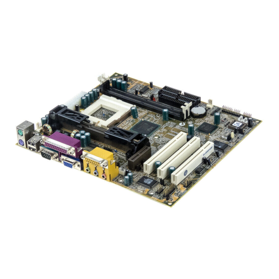
Page 17: Preparing The Mainboard
Preparing the Mainboard Mainboard Guide Use the following illustration and key to identify the components on your mainboard. DIMM2 CPUFAN1 ATX1 DIMM1 PWRFAN1 Socket-370 FDD1 IDE2 IDE1 Slot-1 SIR1 CASFAN1 CDIN2 CDIN1 PANEL PCI1 WOL1 PCI2 SPDIF1 PCI3 WOM1... - Page 18 Key to Mainboard Components Component Description Slot-1 Slot for Slot-1 processor cartridge Socket-370 Socket for PPGA Celeron Processor PCI 1,2,3 Three 32-bit PCI Slots Slot for an AMR (Audio Modem Riser) card. DIMM 1, 2 Two slots for 168-pin SDRAM memory modules FDD1 Connector for floppy disk drives IDE1, IDE2...
-
Page 19: I/O Ports Side View
I/O Ports Side View PS2KBM LPT1 COM1 VGA1 USB1 Key to I/O Ports Component Description PS2KBM1 PS/2 port for pointing device (upper port) PS/2 port for keyboard (lower port) LPT1 External parallel port J2 (Upper) External game/MIDI port J2 (Lower) Audio jacks for (left to right) line out, line in, microphone VGA1... -
Page 20: Check The Jumper Settings
Check the Jumper Settings Check all the mainboard jumpers to ensure that the board is configured correctly. JP1 Clear CMOS Memory Jumper This jumper lets you erase the system setup settings that are stored in CMOS memory. You might need to erase this data if incorrect settings are preventing your system from operating. - Page 21 JP3: Keyboard Power On Jumper This jumper lets you use a typed-in password as a power switch to turn your system on. If you enable this property, you need to define the password or the hot keys using the setup utility. See Chapter 3. Function Jumper Cap Disable keyboard power on...
- Page 22 JP6: Select audio codec jumper Use this 3-pin jumper to select if the system uses the audio codec chip installed on the mainboard, or an audio codec chip located on an optional AMR (Audio Modem Riser) card. Function Jumper Cap Turn on onboard codec Short pins 1-2 Turn off onboard codec...
-
Page 23: Install The Mainboard In The Case
Install the Mainboard in the Case The mainboard is drilled with a series of holes. Most system cases have mounting brackets installed in the case which correspond to the holes in the mainboard. You can secure the mainboard in the system case by placing the mainboard over the mounting brackets and driving screws through the mainboard into the mounting brackets. - Page 24 The illustration below shows the mainboard installing into a tower-type case. Power Supply Unit Drive Cage Template Expansion Slots...
-
Page 25: Connecting Power, Chassis Fans, Panel & Case Open
Connecting Power, Chassis Fans, Panel & Case Open After you have installed the mainboard into the system case, connect the power cable from the case power supply unit to the mainboard power connector ATX1. Connect the chassis/power fans (if your case has them) to the 12V power supply connectors CASFAN1or PWRFAN1 on the mainboard. - Page 26 Panel Connector The mainboard PANEL connector has a standard set of switch and indicator connectors that are commonly found on ATX system cases. Use the illustration below to make the correct connections to the case switches and indicators. 22 21 PANEL Power SW 21-22 SMI Button 19-20...
-
Page 27: Install Other Hardware
Install Other Hardware Start installing the essential hardware required to get your system started. Install the Processor This mainboard has a Slot1 processor slot and a Socket-370 processor socket. You can only install one processor however, so you must choose what kind of processor to run on this. -
Page 28: Installing A Slot1 Processor
About Socket-370 Processors The socket-370 only supports the Intel PPGA Celeron processor. Intel PPGA Celeron PPGA stands for Plastic Pin Grid Array. This is a description of the square plastic package that the processor is embedded in. The PPGA Celeron is identical to the SEPP Celeron, except for the external packaging. - Page 29 Some cartridge holders are secured in place with screws. If you have this kind of cartridge holder, don’ t overtighten the screws as this can stress the mainboard. Some cartridge holders are secured in place with plastic pins. In this case, place the mainboard on a foam plastic mat when you push the pins into place.
-
Page 30: Installing A Socket-370 Processor
you start the system, immediately enter the setup system and make the appropriate settings. Usually, you can automatically configure the CPU by using the BIOS Features page of the setup utility. See Chapter 3 for more information. Installing a Socket-370 Processor If you have decided to install the mainboard with a PPGA Celeron processor, follow the steps below. - Page 31 6. Locate the power cable on the heatsink/cooling fan assembly that is attached to the top of the processor. 7. Plug the power cable into the CPUFAN1 12V power supply on the mainboard. Socket-370 processor with heatsink/cooling Cooling fan fan assembly power cable CPUFAN1 cooling fan power supply...
-
Page 32: Install The Memory Modules
Install the Memory Modules For this mainboard, you must use 168-pin 3.3V non-buffered Dual In-line Memory Modules (DIMMs). The memory chips must be standard or registered SDRAM (Synchronous Dynamic Random Access Memory). The memory bus can run at 66 MHz or 100 MHz. If your processor operates over a 100 MHz system bus, you must install PC-100 memory that also operates over a 100 MHz bus. -
Page 33: Install A Hard Disk Drive And Cd-Rom
3. Push the latches on each side of the DIMM slot down. 4. Install the DIMM module into the slot and press it carefully but firmly down so that it seats correctly. The latches at either side of the slot will be levered upwards and latch on to the edges of the DIMM when it is installed correctly. - Page 34 Installing a Hard Disk Drive 1. Install the hard disk drive into the drive cage in your system case. 2. Plug the IDE cable into the primary IDE channel on the mainboard IDE1. 3. Plug one of the connectors on the IDE cable into the IDE connector on the back edge of the hard disk drive.
- Page 35 Installing a CD-ROM/DVD Drive 1. Install the CD-ROM/DVD drive into the drive cage in your system case. Plug the IDE cable into the primary IDE channel on the mainboard IDE1. 2. Plug one of the connectors on the IDE cable into the IDE connector on the back edge of the CD-ROM/DVD drive.
-
Page 36: Installing A Floppy Diskette Drive
Installing a Floppy Diskette Drive The mainboard has a floppy diskette drive interface and it ships with a diskette drive ribbon cable that supports one or two floppy diskette drives. You can install a 5.25” drive or a 3.5” drive with various capacities. The floppy diskette drive cable has one type of connector for a 5.25”... -
Page 37: Using The Expansion Slots
Using the Expansion Slots This mainboard has three 32-bit PCI expansion slots and one AMR slot. PCI Slot: The PCI slot can be used to install add-in cards that have the 32-bit PCI (Peripheral Components Interconnect) interface. AMR Slot: The AMR (Audio Modem Riser) slot is an industry standard slot that allows for the installation of a special audio/modem riser card. - Page 38 6. Secure the metal bracket of the card in the empty slot in the system case with a screw. 7. For some add-in cards, for example graphics adapters and network adapters, you have to install drivers and software before you can begin using the add-in card.
-
Page 39: Add-In Card Options
Add-in Card Options The mainboard has two features that can be used if you have installed either a fax/modem card or a network adapter card. WOL1: Wake on LAN If you have installed a network adapter (LAN adapter), you can use the cable provided with the card to plug into the WOL1 connector on the mainboard. -
Page 40: Install Options And Extension Brackets
Install Options and Extension Brackets This mainboard has a number of special connectors that allow you to add optional features to your system. You can install any of the following items: ♦ Fax/modem card option ♦ Network adapter extension bracket ♦... - Page 41 Line and Tel Fax/modem RJ11 sockets card fax/modem connector Network Adapter Extension Bracket You must install the network adapter extension bracket in order to use the built-in 10BaseT/100BaseTX LAN adapter. The network adapter extension bracket is supplied with this mainboard. 1.
- Page 42 Infrared Port This option can be purchased from third-party vendors. SIR1 1. If you are installing an optional serial infrared port, connect the cable from the optional IR port to the SIR1 connector on the mainboard. 2. After you have connected the cable, secure the optional IR port to the appropriate place on your system case.
- Page 43 Digital Audio Extension Bracket You can purchase an optional 24-bit digital audio extension bracket from a third-party vendor. You can use the audio RCA jacks to connect to digital audio devices. If your CD-ROM/DVD drive has digital audio output, you can connect it to the input pins of the SPDIF connector. Audio Input Pins SPDIF1...
-
Page 44: Make The External Connections
Make the External Connections After you have installed the mainboard, make the connections to the external ports. PS2KBM1 LPT1 USB1 COM1 VGA1 1. PS2KBM1 is a stack of two PS/2 mini-DIN ports. The upper port can be used by a PS/2 mouse or pointing device. The lower port can be used by a PS/2 keyboard. -
Page 45: External Connector Color Coding
External Connector Color Coding To help identify the external connectors, many connectors now use standard colors as shown in the table below. Connector Color Analog VGA Blue Audio line in Light blue Audio line out Lime Digital monitor / flat panel White IEEE 1394 Grey... -
Page 46: Chapter 3: Setup
About the Setup Utility This chapter explains how to use and modify the BIOS setup utility that is stored on the mainboard. The setup utility stores data about the mainboard components and the configuration of devices that are connected to it. This information is used to test and initialize components at start-up time and to make sure everything runs properly when the system is operating. - Page 47 Some options (marked with a triangle) lead to tables of items that usually have a value on the right side. The value of the first item is highlighted, and you can use the cursor arrow keys to select any of the other values in the table of items.
-
Page 48: How To Flash A New Bios
How to Flash a New BIOS You can install an updated BIOS for this motherboard that you can download from the manufacturer’ s website. New BIOS may provide support for new peripherals, improvements in performance or fixes to address known bugs. Install a new BIOS as follows: 1. -
Page 49: Standard Cmos Features Option
9. In the opening dialog box, type in the filename of the new BIOS and follow the onscreen directions to flash the new BIOS to the motherboard. 10. When the installation is complete, remove the floppy diskette from the diskette drive and restart your computer. If your mainboard has a Flash BIOS jumper, don’... - Page 50 IDE HDD Auto-Detection Press Enter while this item is highlighted if you want the setup utility to automatically detect and configure a hard disk drive on the IDE channel. IDE Primary/Secondary Master/Slave If you leave this item at Auto, the system will automatically detect and configure any IDE devices it finds.
-
Page 51: Advanced Bios Features Setup Option
Halt On Default: All Errors This item defines the operation of the system POST (Power On Self Test) routine. You can use this item to select which kind of errors in the POST are sufficient to halt the system. Base Memory, Extended Memory, Total Memory These items are automatically detected by the system at start up time. - Page 52 External Cache Default: Enabled Most processors that can be installed in this system use external (L2) cache memory to improve performance. The exceptions are older SEPP Celeron CPUs running at 266 or 300 MHz. Enable this item for all but these two processors. CPU L2 Cache ECC Checking Default: Enabled This item enables or disables ECC (Error Correction Code) error checking on the...
-
Page 53: Advanced Chipset Features Option
Typematic Rate Setting Default: Disabled If this item is enabled, you can use the following two items to set the typematic rate and the typematic delay settings for your keyboard. Typematic Rate (Chars/Sec) Default: 6 If the item Typematic Rate Setting is enabled, you can use this item to define how many characters per second are generated by a held-down key. - Page 54 SDRAM CAS latency Time Default: 3 SDRAM Cycle Time Tras/Trc Default: 6/8 SDRAM RAS-to-CAS Delay Default: 3 SDRAM RAS Precharge Time Default: 3 These four items set the timing and wait states for SDRAM memory. We recommend that you leave these items at the default value. System BIOS Cacheable Default: Enabled Video BIOS Cacheable...
-
Page 55: Integrated Peripherals Option
Integrated Peripherals Option This option displays a list of items which defines the operation of some peripheral items on the system’ s input/output ports. On-Chip Primary PCI IDE Default: Enabled On-Chip Secondary PCI IDE Default: Enabled Use these items to enable or disable the PCI IDE channels that are integrated on this mainboard. - Page 56 USB Controller Default: Enabled Use this item to enable the USB ports that are integrated on this mainboard. USB Keyboard Support Default: Disabled Enable this item if you are using a keyboard connected through the USB Port. Init Display First Default: PCI Slot Use this item to define if your graphics adapter is installed in one of the PCI slots or select Onboard if you have a graphics system integrated on the mainboard.
- Page 57 Onboard IR Default: Disabled If you have installed an optional infrared device, you must change the setting of this item to Enabled. UART Mode Select Default: IrDA UR2 Duplex Mode DefaultL Half This item defines the operation of serial port 2. In the Normal setting, serial port 2 is assigned to the external COM2 connector.
-
Page 58: Power Management Setup Option
Power Management Setup Option This option displays items that let you control the system power management. Modern operating systems take care of much of the power management. This mainboard supports ACPI (advanced configuration and power interface). The system has various power saving modes including powering down the hard disk, turning off the video, suspending to RAM, and a software power down that allows the system to be automatically resumed by certain events. - Page 59 ACPI Function Default: Enabled This mainboard supports ACPI (Advanced Configuration and Power management Interface). Use this item to enable or disable the ACPI feature. ACPI Suspend Type Default: S1 (POS) Use this item to define how your system suspends. In the default, S1(POS), the suspend mode is equivalent to a software power down.
- Page 60 Wake Up by PCI Card Default: Disabled If you enable this item, it allows activity on an add-in card in one of the PCI slots to resume the system from a power-saving mode. Power On by Ring Default: Disabled If this item is enabled, it allows the system to resume from a software powerdown or a power-saving mode whenever there is an incoming call to an installed fax/modem.
-
Page 61: Pnp/Pci Configuration Option
PNP/PCI Configuration Option This option displays a table of items that configures how PNP (Plug and Play) and PCI expansion cards operate in your system. Reset Configuration Data Default: Disabled If you enable this item and restart the system, any PNP configuration data stored in the BIOS setup is cleared from memory. -
Page 62: Pci Health Status Option
PCI/VGA Palette Snoop Default: Disabled This item is designed to overcome some problems that can be caused by some non-standard VGA cards. This board includes a built-in VGA system that does not require palette snooping so you must leave this item disabled. PCI Health Status Option On mainboards which support hardware monitoring, this item lets you set parameters for critical voltages, critical temperatures, and fan speeds. -
Page 63: Frequency Voltage Control Option
Frequency Voltage Control Option This item allows you to set the clock speed and system bus for your system. The clock speed and system bus are determined by the kind of processor you have installed in your system. Auto Detect DIMM/PCI Clk Default: Disabled When this item is enabled, BIOS will disabled the clock signal of free DIMM and PCI slots. -
Page 64: Load Fail-Safe Defaults Option
Load Fail-Safe Defaults Option This option opens a dialog box that lets you install fail-safe defaults for all appropriate items in the whole setup utility. Press the Y key and then Enter to install the defaults. Press the N key and then Enter to not install the defaults. -
Page 65: Save And Exit Setup Option
press Enter, or just press Enter if you are deleting a password that is already installed. 5. If you typed the password correctly, the password will be installed. Save And Exit Setup Option Highlight this item and press Enter to save the changes that you have made in the setup utility and exit the setup program. -
Page 66: Chapter 4: Software
The folder for this mainboard is stored in the P6IWT-Me folder. Note: Never try to install software from a folder that is not specified for use with your mainboard. - Page 67 Intel chipsets under Windows 95/98. q VGA: This folder has drivers and software for the graphics system built into the Intel 810 chipset. P6IWT-Me Folder You can use the software in the following sub-folders: q MONITOR : Hardware monitoring software for Windows 95/98, and Windows NT4.0/5.0...
-
Page 68: Running The Support Cd-Rom
Running the Support CD-ROM 1. Place the disk in your CD-ROM drive. If you are running Windows with Autoplay enabled, the opening screen of the CD appears automatically. Click on READ ME to read the latest instructions. 2. Click on the item BROWSE THE CD TITLE. This uses Windows Explorer to show the contents of the support CD. -
Page 69: Cmi8X38 Folder Installation Notes
PC-Cillin Anti-Virus Utility Anti-virus software is provided for DOS, for WIN95, and WIN 98. Log on to the appropriate directory for your operating system. For DOS, copy all the files in the DOS folder to your hard disk drive. For Windows 95, log on to the Disk 1 folder and run SETUP. -
Page 70: Modem Driver And Software
Modem Driver and Software Install the Modem driver from the sub-folders for Windows 95/98 or Windows NT4.0. Windows 95/98 The modem is a plug and play device so Windows 95/98 will automatically detect the presence of your modem. When the Plug and Play wizard begins to look for modem drivers, click on the button that says Have Disk and then browse or type in the pathname to the CMI8x58\modem\win9x folder. -
Page 71: Mainboard (P6Iwt-Me) Installation Notes
810 chipset. Select the folder for the operating system that you are running and then begin the installation by running SETUP.EXE. Mainboard (P6IWT-Me) Installation Notes Most of the sub-folders in this folder are empty, with a short README file giving directions to alternate folders for the appropriate software. Two folders contain software that you can install. -
Page 72: Appendix 1: Quick Jumper Setting Reference
Appendix 1: Quick Jumper Setting Reference JP1: Clear CMOS memory jumper Use this 3-pin jumper top clear all the current data stored in the CMOS memory. Function Jumper Cap Normal operation Short pins 1-2 Clear CMOS Short pins 2-3 JP3: Keyboard power on jumper Use this 3-pin jumper to enable keyboard power on with hot keys or password. - Page 73 JP6: Audio codec select junper Use this jumper to select if the system uses the audio codec chip integrated on the mainboard, or an audio codec chip located on an optional AMR card. Function Jumper Cap 1 2 3 Turn on onboard codec Short Pins 1-2 Turn off onboard codec Short pins 2-3...