Panasonic PT-43LC14 Operating Instructions Manual
Multimedia projection display
Hide thumbs
Also See for PT-43LC14:
- Operating instructions manual (95 pages) ,
- Lamp replacement update (2 pages)
Table of Contents
Advertisement
Quick Links
Panasonic
Models No.
I
MuitiMediaCard
TM
--
logol
--
(USA)
For assistance,
please
call :
1-888-V_EW
PTV(843-9788}
05 contact us via the web at:
http:flwww.panasonic.comlcontactinfo
(Puerto
Rico)
For assistance,
p_ease call :
787-750-4300
or visit us at www.panasonicpr.com
Three
_mportant
Reasons
to Register
Your
Product
Immediately!
1
Protect Your Newlnvestment,..
Register your new projection display for insurance purposes
in case your new projection display is stolen.
2
Product safety notification...
Registering your product can help us to contact you in the
unlikely event a safety notification is required under the
Consumer Product Safety Act,
3
Improved
Product
Development...
Help us continue to design products that meet your needs.
Register online at www.panasonic.com/register
As an ENERGY
STAR "_Partner, Matsushita Electric Corporation
of America has determined that this product or product model
meets the ENERGY
STAR "_guidelines for energy efficiency.
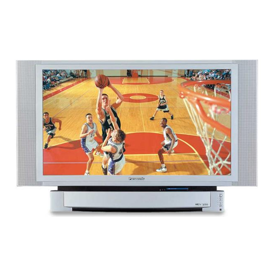
This operating instruction book is designed for use with models PT=43LC14, PT=50LC14 and PT=60LC14.
Illustrations in this manual show the PT=50LC14.
Before connecting, operating or adjusting this product, please read the instructions completely.
Please keep this manual for future reference.
LSQT0834
A
Advertisement
Table of Contents

Related Manuals for Panasonic PT-43LC14


Summary of Contents for Panasonic PT-43LC14
- Page 1 Development... 787-750-4300 Help us continue to design products that meet your needs. or visit us at www.panasonicpr.com Register online at www.panasonic.com/register As an ENERGY STAR "_Partner, Matsushita Electric Corporation of America has determined that this product or product model meets the ENERGY STAR "_guidelines for energy efficiency.
- Page 2 CAUTION WARNING: To reduce the risk of electric shock, do net remove cover or back. No user_serviceable parts inside, Refer servicing to qualified service personnel This symbol warns the user This symbol alerts the that uninsulated voltage user that important representation of a hot he pictorial...
- Page 3 AS WiTH ANY SMALL OBJECT, SD CARDS CAN BE SWALLOWED BY YOUNG CHLDREN. DO NOT ALLOW CHILDREN TO HANDLE THE SD CARD. This projection dispJay is intended to be used with the following TV stand: model TYo43LCt4C for the PT-43LC14, TY=50LC14C for the PT=50LC14, and TY60LC14C...
- Page 4 Visit our" Pcmasot:,ie Web Sife f)r" USA : www.panasot:,ie.eom (USA) For assistance, pmeasecall : 1-888-VIEW PTV(843-9788) or_ contact us via the web at: http:llwww.panasonic.comlcontactinfo (Puerto Rico) For assistance, please call : 787-750-4300 or visit us at www.panasonicpr.com...
-
Page 5: Table Of Contents
,& iMPORTANT SAFETY _NSTRUCT_ONS ............... Dear Panasonic Customer ....................Before Using ........................Start! Location of Controls ......................Installation ........................Power ON and OFF ......................Basic Menu Navigation ....................Tuning channels ......................Projection display operation ..................Searching for the desired channet (Channel search} .......... - Page 6 Receiver Location This projection display is intended to be used with an optionN stand or entertainment center. Consult your dealer for available options. Locate for comfortable viewing. Avoid placing where sunlight or other bright light (including reflections) will fall on the screen.
-
Page 7: Before Using
Before Using Remote Control (EUR7627Z20) Batteries 2"AA" RGB Cable (2 m) (LSJA0239-1 or LSJA0443) Remote Control Battery Installation Requires two AA batteries (supplied). Install the batteries as shown in Press cover in direction of While pressing in on the catch, open cover in direction of arrow. - Page 8 Illuminated Remote Control --21 STOP --26 SPLIT OH DVD VCR CH - --2g Note: * This section describes TV mode only. For other modes, see pages 75-81,...
-
Page 9: Location Of Controls
Location of Controls POWER Press to turn ON and OFR Sets the remote to communicate with television. VCR, DVD, DTV, RCVR_ Sets the remote to communicate with other devices. DBS/OBL, AUX TV/VIDEO Changes Input source. Accesses the Photo Viewer feature (SD Card or PC Card). ASPECT Changes display aspect ratio. - Page 10 Location of Controms Controms and Terminals on the projection dispmay Node_ PT°50LC14 unit shown < FRONT > POWER POWER button/ POWER indicator STANDBY(R) (PP. 22, 74) ON(G) ::: ......volume up(+)/ down(-) buttons _(P. Channel up / down buttons _(P. TV!VIDEO TV/VIDEO button (P.
- Page 11 Location of CootroJs Mode_ PT°50LC14 unit shown < REAR > < SIDE > Vent RGB Input 1 terminal HDMI Input terminal (For P%50LC14/P%60LC14) (P. 20) (P. 18) RGB (P%43LC14) or RGB2 (P%50LC14/ VHF/UHF P%60LC14) Input terminal terminal (R 18) PP. 12-14) Input 3 terminals Component signal input 1-4 terminals Input 1, 2 terminals...
- Page 12 Notes on connections • Turn off the power supply for al! components before making any connections, • If the cables necessary for connecting a component to the system are not included with the component or available as an option, you may need to fashion a cable to suit the component concerned.
-
Page 13: Installation
Installation Cable Connection Use this configuration when connecting the projection display to a cable TV system. CABLE BOX THE BACK OF TERMINAL ON [ THE CABLE © " iNPUT OUTPUT L ..mmmmm_ Infrom cable Connect the cable from the antenna or cable system to the VHF/UHF terminal on the back of the projection display. - Page 14 Installation Connecting the Antenna / CaNe to the RF IN TerminaJ {VCR) Use this configuration when connecting the projection display to a cane TV system using VCR. °El © Cem_ect the cable t]-om the Omput terminal on the back of the Cable Box or aatenna/cable system to the Antenna input terminal on the back of the VCR.
- Page 15 installation How to connect the "1, 2, 3" Input Terminals Connects VCRs other peripheral equipment (S-VHS VCR) ©1©© ©©© ©©© Similar connections are available at the INPUT 1, 2, 3 input terminals. (P.11) (VHS VCR) Audio Video el® 1( ov.._ ¢ ) Similar connections are available at the INPUT 1, 2, 3 input terminals.
- Page 16 InstaJJation How to connect the COMPONENT VIDEO input TerminaJs Because each Y, PB, and PR signal is input independentJy, the Component signal aiiows for more accurate color reproduction. The Component signal output terminat indication will differ according to the output device (Y, PB, PR). PJease read the operating instructions included with the output device.
- Page 17 Installation How to connect the AV OUT Terminals The "AV Out" Terminals output the same signals as the main picture on the projection display screen and sound from the speaker at that time, e.g. TV programs or signals from iNPUT 1, 2, 3 terminals. Recording Equipment IvHs VCR) Audio...
- Page 18 InstNlation How to connect the RGB mNTerminals Connecting a PC to RGB _N COMPUTER AUDIO OUT RGB OUT Conversion adapter Example: (If necessary) PTo50LC I4/PTo 60LC 14 RGB cable (D-SUB !5P) Connect a cable v, hich matches the audio output terminal on the computer.
- Page 19 installation RGB signals that can be input The table below lists the different types of RGB signals that can be input. if a signat which differs greatly from any of the types listed below is input, the picture image may not be displayed correctly, or a black background...
- Page 20 Installation How to connect the HDN[ input Terminal About HDN[ HDM[ is the first all digitN consumer electronics A/V interface that supports several uncompressed standard, enhanced and high definition video format as well as all existing multi-channel audio formats. One jack supports both video and audio information.
- Page 21 Installation Procedure Connect the HDMI output from the set top box or a DVD player to the HDMI input on the back of the unit. • If you cannot display the picture because your Digital Set Top Box does not have a Digital Out terminal setting, use the Component Video input (or the S-Video Input or Video Input).
-
Page 22: Power On And Off
ing the Power ON and OFF Always be sure to follow the procedure given below to turn the projection display power ON and OFF. • The lamp cooling fan will continue to operate for approximately 1 minute after the power is turned off, At the same time, POWER... - Page 23 Power ON 1OFF First Time Setup in order to view TV or Cable programs, it is necessary to perform channel setting. Jf needed, foJtow the menus and procedures dispJayed on-screen for setting up the features. input Setup To select the configuration of RF input depending on the signaJ source.
- Page 24 i ¸ i ¸i ¸¸¸¸¸¸ Pressing the MENU button dispJays the MENU screen. to select the desired Press menu, MENU Note: i_ii_,i _III!' ' • Depending on the signal being input, some items may or may not be adjustable and some functions may oF may not be available.
-
Page 25: Basic Menu Navigation
Basic Menu Navigation Continued from left column, Continued from page 24. Press @COLOR IIIIIIIIIIIIiIIiI[_ Note: For OTHER ADJUST sub-menu to set or adjust desired Press to select OTHER ADJUST _- [ ( r_J,, SEL_ _i _i_ii_ _i_i__iii_iii_i_i i I I i _ i _ii_ Note: To EXmT menus. - Page 26 Automatic channel setting Automatically searches and adds receivable channels to memory. Press the MENU button to display the MENU screen. Press to display the CHANNEL screen. Press to select ANTENNA. Press to select TV or CABLE. Press to select AUTO SET. Press to run AUTO SET Note:...
-
Page 27: Tuning Channels
Tuning channels When setup is complete, the lowest channel picture appears. if setup is incomplete, the screen at right appears. Check connection of Antenna/Cable to the RF in Terminal, then try Automatic Channel Setting again. EXiT Press to exit menu. Notes: •... - Page 28 Tuning channels Manuam channem setting Use this setting when changBng setting of receiving channels or changBng the channel display. Press the MENU button to display the MENU screen. Press to select _ENUO OEN_ i ¸ ii:E i ¸:t !::i CHANNEL. Press to display the CHANNEL screen.
- Page 29 Tuning channels To add channem Press to select channel. add channels to memory. Press to To delete channe_ Press to select channel....Press to delete channels from memory. Repeat step 4 to continue adding or deleting channels. EXIT Press to exit menu. Note: •...
- Page 30 Operation can be done from the projection display. POWER POWER button/ POWER indicator ON(G) Volume up(+) / do'an( ) buttons Channel up / down buttons Remote Control Sensor TV/VIDEO TV/V][DEO button display with the Remote Control. Press to operate the projection Press to turn the projection display on.
-
Page 31: Projection Display Operation
Projection display operation TV status display (R 32) except when the MENU (P. 53) screen is displayed, to display broadcast types Press the RECALL button, caption current TV status information. (R 37) Using the Number keys When selecting CABLE channels 100 to 125 with the Number keys, first press the 1 key, and then enter the remaining two digits. - Page 32 The color monitor witi allow you to enjoy viewing the picture at its maximum size, including wide screen cinema format picture, The aspect mode changes each time the ASPECT button is pressed. NORMAL FULL • When a 480p signal is being received, the mode switches between NORMAL,...
- Page 33 ASPECT Controls Mode Picture Explanation NORMAL will display a 4:3 picture at its NORMAL standard 4:3 size. JUST mode will display a 4:3 picture at maximum size but with aspect correction applied to the center of the screen so that JUST elongation is only apparent at the left and right edges of the screen.
- Page 34 Channem search disNays each channel, in order, as a paused image. Channels are displayed from the left top to the right bottom in order. When it reaches the right bottom, the next channel is displayed at the [eft top, overwriting the previously displayed channel.
- Page 35 Confirming connections A video camera uses the input 3 terminN on the front of the projection display. Example: Connect Ii1 _ut3 To S<ideo output S-VIDEO Video camera or video output fy_x_ DVDplayer --<2Z_ <CZ3? \\_21 VIDEO This equipment can 11o 11 also be connected to the rear terminals.
- Page 36 Sound mute Useful when answering the phone or receiving unexpected visitors Press this button to mute the sound. Press again to reactivate sound. Sound is also reactivated when power is turned off or volume level is changed. Note: • The audio output from A\/OUT is not muted. Freezing pictures FREEZE...
- Page 37 Mute / Freeze I SAP Receivabme Broadcast Types The following are possible broadcast types with their accompanying on=screen displays. The signal being received is indicated with a "t(," mark while the selected audio mode is indicated with an arrow. To change the audio mode for these broadcasts, follow the "Select Audio Mode for TV Viewing"...
- Page 38 Splitting the screen SPLIT PL_,Y Press to split. (The previously selected screen appears on the left.) - Right screen Let'[ screen (Main picture) (Sub picture) Returning to one screen 8PLUT PLAY Press to return. SWAP SPLIT PLAY Notes: Sound from the Left screen is output from the speakers on the projection...
-
Page 39: Split Screen
Split screen Changing the channe_ of the right screen Swapping _eft and right screens SPLIT SWAP Press to select the desired Press to swap. I) V[_NC r,_C channel. Example: During SPLIT SCREEN NORMAL Example: Dmil_g SPLIT SCREEN NORMAL SPLIT CH A, _' buttons can also be used to select Note: an outside input for the right side of the screen. - Page 40 Press to select the screen mode. Press the MENU button to display the MENU screen. to select OTHER. Press to display OTHER screen. ii i i!_ ili !¸ill¸! _iii_ i_! "i' ii _ _oLEcTo_ to select POSFION/SIZE. Press to display JUST mode POSFION/SIZE sub-menu.
-
Page 41: Adjusting Screen Position And Size
Adjusting screen position and size Adjustment Button Adjustment Details Note item Press I_ button. The image moves to the right. H Position PC input Press _ button. The image moves to the left. Press I_ button. The image moves up. V Position PC input Press _ button. - Page 42 Press the MENU button to display the MENU screen. to select _AODz0 AUDIO. sELzc_ C.N_ IZ_Z_iiiiiiiiiiiiiI Press to display AUDIO screen. to select each item. Note: • NORMAL is displayed at default, repeatedly to select MODE. -_uzDt_ A b D Z 6 /fZ'_ sE LECT 0'430...
-
Page 43: Audio Adjustments
Audio Adjustments OTHER ADJUST While in the AUDIO menu screen, select OTHER ADJSUT and press the OK button to display the OTHER ADJUST sub-menu. m BBE: i_! i_il ii_i ii _ iiii i_ i iilii :i SPEAKER Natural sound is offered. (See below.) --AUDIO SELECT (HDMI input only): Perform input switching of analog audio input and digital audio input when using the HDM[ terminal. - Page 44 Press the MENU button to display the MENU screen. Press to select PICTURE. Press to display PICTURE screen. Press to select each item. Note: • NORMAL is displayed at default, PICMODE: Lets you choose one of three pre-set Picture Modes that best suits the program you are wewing.
-
Page 45: Picture Adjustments
Picture Adjustments COLOR TiNT BRIGHTNESS PICTURE SHARPNESS Adjust to desired level while viewing picture through the menu overlay. Press the MENU button or wait a few seconds to return to the previous menu screen. EXmT Press to exit menu. Adjustment item Button Adjustment... - Page 46 This projection display has a buittAn V=Chip Control which atlows you to block unwanted TV usage based on US MOVES and US TV PROGRAMS ratings. Enter Secret Code A 4=digit code must be entered to view a blocked program or change rating settings.
-
Page 47: Lock Feature
Lock Feature Setup US MOVIES Ratings Perform "Enter Secret Code" step 1 on page 46. Press Number keys to enter your secret code. ENTER 4L[)_'GIT CODE Press to set. Press to select V=Chip Control is US MOVIES. activated. L6CE MENk) _.X:[ OFF: V=Chip Control is... - Page 48 Lock Feature Setup US TV PROGRAMS Ratings Perform "US MOVIES Ratings" step 1 on page 47. select US TV PROGRAMS. Press to set. VzChip Control is activated. OFF: WChip Control is deactivated. select ..Go_o_ CHANGE SETTINGS. Press to display the CHANGE SETTINGS screen.
- Page 49 Lock Feature GENERAL AUDIENCE: <When V-Chip Control is activated> All ages admitted. PARENTAL GUIDANCE SUGGESTED: Some materials may not be suitable for children. PARENTS CAUTIONED: PROGRAM RATING EXCEEDED PG-13 Some materials may be inappropriate for RATING : TV children under 13. RESTRICTED CODE Children under 17 must be accompanied...
- Page 50 This receiver has a built in decoder that provides a visual depiction of the audio portion of a television program in the form of written words across the screen (white or colored letters on a black background), atlows the viewer to read the diatogue of a television program or other information.
-
Page 51: Closed Captions
Closed Captions CC ON MUTE Activates the On-Screen Closed Caption feature, when the MUTE button on the Remote Control is pressed. To deactivate, press the MUTE button again. Note: • This feature functions when the Closed Caption Mode is in the "OFF" position, The program being viewed must be broadcas... -
Page 52: Input Label
To label video input connections for on=screen display. Press the MENU button to display the MENU screen. Press to select SETUR SETUP _SELECm _ENU iII il ,i_ i ! i_i , i_ ii_ ,i_i_ i _i _ii ,_i_i, _i_:_ii_i_i ' _' i_i_ _ _ Press to display the •... -
Page 53: Channel Caption Feature
Station names, e.g. ABC_ TNN, etc. so that they will appear when a channel is selected. Choose 24 preset names, Press the MENU button to display the MENU screen. Press to select CHANNEL. _iii _ii _ iI ii .._u_,E_ Press to display the CHANNEL screen. - Page 54 When "ON" Essemected, the picture is displayed even when a broadcast signal is weak or non-existent, Press the MENU button to display the MENU screen. Press to select ,tHAN N E • _X SE•EC_T ii _ i! ill ! _!i :i _°T !i_ CHANNEL.
-
Page 55: Color Temp Feature
To increase or decrease Warm (red) and Cool (blue) colors to suit personal preferences. Press the MENU button to display the MENU screen. Press to select PICTURE. Press to display the PICTURE screen. Press to select OTHER ADJUST. Press to display the OTHER ADJUST screen. - Page 56 if the picture has a reddish or blueishtint, o r if thewh{teness isnotat the desired levei, y ou can adjustthe white balance. (The fol!owing steps show R Level adjustment.) Press the MENU button to display the MENU screen. to select PICTURE.
-
Page 57: Video Nr (Noise Reduction)
in the event of weak signal conditions, the Video NR circuitry reduces noise in the luminance channel, it is important to note that Video NR should remain OFF for maximum picture detail when receiving a strong signat or viewing high-quality video. - Page 58 If the received signal contains screen size specifications in RF, VIDEO iNPUT (1-3) or COMPONENT VIDEO iNPUT (1-4)_ the screen s{ze is automatically changed. Press the MENU button to display the MENU screen. Press to select PICTURE. Press to display the PICTURE screen.
- Page 59 Adjust 480p signamsto achieve a natutam color from digitat equipment connected to COMPONENT VIDEO iNPUT (Y, PB, PR input term{nares). Press the MENU button to display the MENU screen. Press to select 'PZCTURE G_JI_E_ PICTURE. i! i _ ¸¸_ il i f! !_i! _ ..
- Page 60 Set the signal to be input to the projection display's RGB JN terminal Most of analog RGB iN signals are setected automat{caliy. When RGB Bnput s{gna{ is VGA 60Hz from PC or 480P from other equipment, must manually sw{tch to the desired input, Press the MENU button to display the MENU screen.
- Page 61 Accurate separation of the picture's brightness and color signals atlows you to enjoy a beautiful picture. Press the MENU button to display the MENU screen. ress to select _PZCTURE _S{JZB[. PICTURE. Press to display the PICTURE screen. Press to select ;...
- Page 62 Film media (taken at 24 frames per second} is faithfully reproduced on the projection display. Press the MENU button to display the MENU screen. Press to select PICTURE. Press to display the PICTURE screen. Press to select OTHER ADJUST. Press to display the OTHER ADJUST screen.
- Page 63 The median brightness Bevel of the picture can be set. Press the MENU button to display the MENU screen. Press to select PICTURE. Press to display the PICTURE screen. Press to select OTHER ADJUST. Press to display the OTHER ADJUST screen. Press to select GAMMA.
- Page 64 You can adjust the gray level of black for areas of the screen that are darker than the median level. Press the MENU button to display the MENU screen. Press to select ,Pzcmu_E _JzD_ PICTURE. i! !_i! i!ii _i' _EL°_ 'i !!ii i _!i:ii::i_ii!:ii,li_i: ii_ !: i ¸!iiiiiiiill ii ¸¸...
- Page 65 With HD!_11 connection, depending on the signal, the picture may be displayed with unnatural colors (as if ted and blue are reversed). Correct by setting the COLOR CORR. to Invert. Press the MENU button to display the MENU screen. Press to select PICTURE.
- Page 66 The projection display can be set to shut itself off at a preselected time. Press the MENU button to display the MENU screen. Press to select OTHER. Press to display the OTHER screen. Press to select SLEEP TIMER. Press repeatedly to select the desired time.
- Page 67 ]'he language of the projection display is set to English as the factory setting, To select one of 3 different languages for on=screen displays, follow the instructions below. Press the MENU button to display the MENU screen. Press to select LANGUAGE.
- Page 68 Still image data (JPEG) made with a digital camera, digital video camera, or PC can be played back using an SD CardlPC Card. As with any small object, SD cards can be swaJlowed by young children. Do not atlow chitdren to handle the SD card.
- Page 69 Photo Viewer (SD CardlPC Card) Compatible Card Insert the Card, Front Card Slot (P. 10) • The media* listed in the right column above can be read via the PC Card in the PC Card adaptor. • Hard disk PC Cards, Flash AT#, Cards, and other recorded...
-
Page 70: Photo Viewer
Photo Viewer (SD Card/PC Card} MENU Area Operation Press to PAGE: select MENU. SD/PC Press to move to index area. SINGLE A single image selected from the index area fills the screen, You can also rotate the image and view image information. (PP. 71-72) SLmDE images are displayed one after another as a slide show. - Page 71 Photo Viewer (SD CardlPC Card) Single P_ay Node MENU- PAGE: SL IDE Press AT to select "SINGLE," and press SO/PC Press A_',_ _ to move cursor to desired file in INDEX AREA. (Press AT _ _ to display next/previous page of 9 thumbnail files), Press OK to display file in full screen size.
- Page 72 Photo Viewer (SD Card/PC Card) S_ide Show Mode Continued from page 71. ZOOM SETTING Press A_' to select "SLIDE," and press OK. A Single View Screen can be changed from Normal Press A_'_ _ to move cursor to desired file in Screen Mode to Zoom Screen Mode by pressing Index Area.
- Page 73 Lamp unit replacement period The Lamp is a consumable item and it's life varies based on individual usage. Panasonic warranties the original Lamp for a period of 1 year from the date of purchase. • The unit will detect when the Lamp's...
- Page 74 icators This unit has indicators (lights on the front) to let you know the unit's internal condition. (See page 10) Depending on the condition, the Lamp, Power, or Temp indicator wiJJflash to aJert you. in this case, turn unit off and folJow the measures below.
- Page 75 Panasonic Code VCR (Preset) Panasonic Code DVD/CD DVD and CD (Preset) Panasonic Code DBS STB & CBL STB (Preset) Panasonic DBS Code and Panasonic DBS/CBL and Cable (Preset) CABLE Code RCVR Audio Receiver (Preset) Panasonic RCVR Code Personal Video Recorders,...
-
Page 76: Remote Control Quick Reference Guide
RemoteControm QuickReferenceGuide (Operating peripheral equipment) Programming Without A Code This procedure searches all codes and is called the "sequence method." Setting to the remote using the step and set method (When code Bsnot known): POWER Confirm that the external component is plugged in and on. - Page 77 80 to 81 for details on operating peripheral equipment using the Remote Control. VCR _nfrared Codes _ndex Brand Code Brand Code _dmirai optimus 306,321,328,335 _iwa Orion 320,326 _kai Panasonic 314,315,316,329 321_322,323, Audio Dynamic 311,339 Penney 300_305,310, 311,324,339,345 Bell & Howell Pentax 305,313 300,311,345 Broksonic...
- Page 78 CONVERTER BOX AND DVD, CD PLAYERS {nfrared Codes {ndex DBSICBL Code BPand Code Bt'and Dish Network Magnavox 101_102 105, 115, 116 (Echostar) Panasonic Echostar Philips 101,102 Express VU 105, 115 Primestar G.E. Proscan 106,109_110_113 GI. (General 106,109,110,113 Instrument) Sony Gradiente...
- Page 79 200_ 207 Sony 219,220 Marantz Teac 210,211_ Nakamichi Technics 216,218 Onkyo 208,209,213 Yamaha 201,202 Panasonic 216,218 Brand Code Panasonic Replay TV 100 Philips Tivo Son}/Tivo Brand Code Brand Code Denon Saba Ferguson Samsung Sharp Mitsubishi Sony Nordmende Technics Panasonic Thomson...
- Page 80 RemoteControlQuickReferenceGuide (Operating peripheral equipment) Operating Components with Remote Contro_ Note: • Refer to pages 8=9 for programming Remote Contro! procedure, Operating a VCR Operating a DBS Program the Remote Control to use with VCR. Program the Remote Control to use with DBS. TO DO THIS.:: PRESS TO DO THIS.;:...
- Page 81 RemoteControl Quick ReferenceGuide (Operating peripheraJequipment) Operating Components with Remote Control Operating a Cassette Deck Operating a Receiver To operate a cassette deck, the Remote Control must be Program the remote to operate audio receiver. in AUX mode and be programmed with the appropriate TO DO THIS.o.
-
Page 82: Cleaning
Before you call for service, determine the symptoms and make a few simple checks shown below. Symptoms Checks Page Power does not turn ON. * Is the power plug plugged in? No picture even if the power is turned ON. * Please replace lamp with a new one, Please consult your nearest 73-74 LAMP indicator blinks red. - Page 83 P%43LCt4 P%50LC14 P%BOLC14 Power Source AC 120 V, 60 Hz Power Consumption Power ON: Approx. 220 W (When audio is at maximum) Power OFF: Approx. 0.4 W (When cooling fan is stopped) 0.9" Poly silicon TFT LCD 0.7" Poly silicon TFT LCD panel x 3 )anel x 3 LCD panems 921 600 (1 280 x 720) stripe pixels x 3 panels (16:9)
- Page 84 Do not use any type of cleansers on the picture screen. Accessorv Purchases Purchase Parts, Accessories and _nstruction Cooks online for a_ Panasonic Products by visiting our Web Site at: or, send your request by E-mail to: _arts@panasonic.com...
-
Page 85: Limited Warranty
If your product does not work properly because of a defect in materials or workmanship, Panasonic Consumer Electronics Company or Panasonic Sales Company (collectively referred to as "the warrantor") will, for the length of the period indicated on the chart below, which starts with the date of original purchase ("warranty period"), at its option either (a) repair your product with new or refurbished parts, or (b) replace it with a new or a refurbished )roduct. - Page 86 1 080i ............... 16, 19,21 480 i ................ 16, 19 OK button ..............9, 24 480 p ..............16, 19, 21 720 p ..............16, 19, 21 PC Card ............... POWER button/POWER indicator ..... 10, 22, 30, 74 ASPECT button ............9, 32 POWER button (Remote Control) ......
- Page 87 Matsushita of Matsushita Electric Corporation of America Electric of Puerto Rico inc. ("PSC") One Panasonic Way Secaucus New Jersey 07094 Ave. 65 de Infanteria, Km 9.5 San Gabriel Industrial Park, Carolina, Puerto Rico 00985 Printed in Indonesia LSQT0834 A S0604-0...