Table of Contents
Advertisement
Quick Links
Download this manual
See also:
Instruction Manual
Advertisement
Table of Contents

Related Manuals for Delta RS830


Summary of Contents for Delta RS830
- Page 1 10" Professional Radial Arm Saw (Model RS830) PART NO. 424-12-651-0034 - 06-17-05 Copyright © 2005 Delta Machinery...
- Page 2 NOT be modified and/or used for any application other than for which it was designed. If you have any questions relative to its application DO NOT use the product until you have written Delta Machinery and we have advised you.
- Page 3 It is important foryouto readandunderstand t hismanual. Theinformation i tcontains relates to protecting YOUR SAFETY andPREVENTING PROBLEMS. Thesymbolsbelowareusedto helpyourecognize t his information. Indicates animminently hazardous situation w hich, i f notavoided, willresult i ndeath orserious injury• Indicates a potentially h azardous situation w hich,if notavoided, couldresult i ndeathor serious injury. Indicates a potentially h azardous situation which, i f notavoided, mayresult i n minor o rmoderate i njury•...
- Page 4 Damage to the machine and/or injury may result. water. 13. USE RECOMMENDED ACCESSORIES. The use of accessories and attachments not recommended by Delta may cause damage to the machine or injury to the user.
- Page 5 FAILURE TO FOLLOW THESE RULES MAY RESULT IN SERIOUS INJURY. DO NOT OPERATE THIS MACHINE UNTIL it is KEEP ARMS, HANDS, AND FINGERS away from the blade. assembled installed according instructions. NEVER REACH around the saw blade. 2. OBTAIN ADVICE from your supervisor, instructor, NEVER PERFORM a "crossed arm"...
- Page 6 POWER CONNECTIONS A separate electrical circuit should be used for your machines. This circuit should not be less than #12 wire and should protected with a 20 Amp time lag fuse. If an extension cord is used, use only 3-wire extension cords which have 3-prong grounding...
- Page 7 240 volts and the rated current of the saw. A qualified electrician should do the conversion, or the machine can be taken to an Authorized Delta Service Center. The machine must conform to the National Electric Code and all local codes and ordinances after the 240 volt plug is assembled.
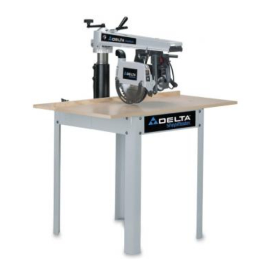
- Page 8 FOREWORD Delta ShopMaster Model RS830 is a 10" (254mm) Professional Radial Arm Saw with maximum cutting capacity of 16" (406mm) crosscut, 2-3/4" (70mm) depth at 90 ° and 2-1/2" (64mm) depth at 45 ° bevel. It is designed with positive bevel stops at 0°, 45 °...
- Page 9 UNPACKING AND CLEANING Carefully unpack the machine and all loose items from the shipping container(s). Remove the protective coating from all unpainted surfaces. This coating may be removed with a soft cloth moistened with kerosene (do not use acetone, gasoline or lacquer thinner for this purpose). After cleaning, cover the unpainted surfaces with a good quality household floor paste wax.
- Page 10 RADIAL ARM SAW PARTS Fig. 4 Radial Arm Saw 5/1 6" Flat Washers (1 6) Legs (4) 5/16" External Tooth Lockwashers (16) Table Supports (2) 5/16-18 Hex Nuts (16) 5/16-18x5/8" Carriage Head Screws (16)
- Page 11 TABLE BOARD PARTS L ......IO'--S_ L ......Fig. 5 Fence Board 1/4-20xl" Round Head Screw (4) Middle Table Board 5/16-18x5/8" Carriage Head Screw (6) Rear Table Board 10. #10xl/2" Sheet Metal Screw (2) Front Table Board 11. 1/4-20 Flange Hex Nut (4) 7/8"...
- Page 12 GUIDE TO PARTS The following is an explanation of the operating controls of the Delta 10" Radial Saw. We suggest you study these explanations carefully to familiarize yourself with the controls before turning on the power. Doing otherwise may cause damage to the saw or personal injury (Figs.
- Page 13 FOR YOUR OWN SAFETY, DO NOT CONNECT THE MACHINE TO THE POWER SOURCE UNTIL THE MACHINE IS COMPLETELY ASSEMBLED AND YOU READ AND UNDERSTAND THE ENTIRE INSTRUCTION MANUAL. ASSEMBLY TOOLS REQUIRED 7/8" Open End - 1/2" Box Wrench (included) 7/8" x 1/2" Box Wrench (included) 1/2"...
- Page 14 REMOVING BLADE AND BLADE GUARD FROM SAW Loosen blade guard clamp knob (A)Fig. 11, and rotate blade guard (B) to the position shown. Fig. 11 With wrenches (C) Fig. 12, loosen arbor nut (D) as much as possible. NOTE: Arbor has left hand threads.
- Page 15 TABLE SUPPORTS Place front table board (A)Fig. 16, on a stable surface with counter-bored holes facing down, shown. Fasten left and right table supports (B) Fig. 16, to bottom of front table board (A) as shown, by inserting four 1/4-20x1" round head screws...
- Page 16 When both right and left edges of the table board are the same distance from the table supports, tighten four screws located in holes (N) Fig. 21, of front table board (A). Insert four 1/4-20x1-1/4" round head screws (P) Fig. 22, into holes (R) Figs.
- Page 17 11. Place an arbor wrench (D)Fig. 25, between table board (A) and motor shaft (B). Lower track arm (X) Fig. 24, by turning elevating handle (C) counterclockwise until motor shaft (B)Fig. 25, barely touches arbor wrench. Fig. 25 12. Check the height of the table board above the other three table board adjustment screws (E) Fig.
- Page 18 TABLE BOARD CLAMPS AND TABLE BOARDS Locate table board clamps (A) Fig. 29, and insert one clamp into each of the slotted holes (B) located at the rear of each table support bracket (C) as shown in Fig. 30. Fig. 29 Turn adjusting screw (D) Fig.
- Page 19 4. Loosencutting-head clampknob(S)Fig.33, and slidecutting-head ( T)theentirelength oftrackarm(A) a s shownto determine if blade(C)travelsparallel t o the square (E). Fig. 33 5. If an adjustment i s necessary, loosenindex ring lockingscrew(J)Fig.34, andtrackarmclamphandle (K). Rotate track arm (A) Fig. 33, until blade (C) travels parallel to square (E).
- Page 20 REMOVING "HEELING" IN SAW BLADE CUT FENCE Even though the cutting-head travel may be perfectly aligned at 90 degrees to the fence, the blade itself may not be 90 degrees or square with the fence, as shown in Fig. 37. This condition is known as "heeling." >...
- Page 21 5. Placea square (D)Fig.41,onthe tableandagainst thesawblade, a s shown, a ndcheckto seeifthe blade is square withthetable.NOTE: T hesquareshouldrest betweentwo teeth of the saw blade. 6. If an adjustment is necessary, makecertainbevel clamplever (C)Fig.40, is tight. Removescrew,flat washer, andpointer(E)Fig.40. Remove t wo screws(F) Fig.40, and bevelscaleplate(H)Fig.42, with index knob(A).
- Page 22 ASSEMBLING BLADE AND BLADE GUARD NOTE: USE ONLY 10" BLADES WITH 5/8" ARBOR HOLES AND RATED FOR 5000 RPM OR HIGHER. Assemble the inside (thick) arbor flange (A) Fig. 44, onto the arbor shaft with the recessed side of flange (A) facing out.
- Page 23 CUTTING INTO TABLE BOARDS Assemble table boards (A) Fig. 48, and fence (B) as shown and secure in place with table clamps, one of which is shown at (C). Return cutting-head (D) Fig. 49, to rear of track arm (E), and tighten cutting-head clamp knob (G) Fig.
- Page 24 IOPERATIONAL CONTROLS AND ADJUSTMENTS STARTING AND STOPING The on/off switch (A) Fig. 56, is located at the front of the cutting-head. To turn the saw "ON" move the switch (A) Fig. 56, up to the "ON" position. To turn the saw "OFF" move the switch (A) Fig.
- Page 25 Using a 3/16" Allen wrench (J) Fig. 64, turn adjustment screws (K) Figs. 61 and 64 to remove all "play." NOTE: DO NOT OVERTIGHTEN ADJUSTMENT SCREWS (K). THIS CAN DAMAGE BEARINGS. LOOSEN ADJUSTMENT SCREWS (K) MORE THAN 1/2 TURN. THE CUTTING- HEAD MAY FALL FROM THE TRACK ARM.
- Page 26 Rotate hex bolt (B)Fig. 67, in the desired direction which the handle needs to be turned. Push hex bolt (B)Fig. 67, back through hole. Make certain head of hex bolt is seated properly in recessed bushing (C), and reassemble track arm clamping lever.
- Page 27 POSITIVE STOP YOKE INDEX Yoke index lever (A)Fig. 71, activates a positive stop which positions the cutting-head in the cross-cut or rip position. To rotate the cutting-head, release yoke clamp handle, press up or down on yoke index lever (A), releasing the positive stop, and rotate the cutting-head to the #1 in-rip or #2 out-rip or #3 cross-cut positions as...
- Page 28 AUXILIARY TABLE BOARD FACING To prevent repeated cutting into the table surface which will eventually cause the table to sag, an auxiliary table board facing can be cut and fitted to the table. It can be made from 1/4" plywood or particle board and should be cut to a size that will exactly cover all of the table boards in front of the fence.
- Page 29 COMPOUND MITER CUTTING Compound miter cutting is performed in the same manner as miter cutting except the saw blade is also tilted to cut a bevel. The settings and operation are similar to miter cutting except that the blade is first tilted to the desired angle on the bevel scale before it is clamped in place.
- Page 30 CONSTRUCTING A PUSH STICK When ripping work less than 4 inches wide, a push stick should be used to complete the feed and could easily be made from scrap material by following the pattern shown in Fig. 83. _'_- ,4,--o (DO-- ..
- Page 31 OR WARRANTY ASSISTANCE All Delta Machines and accessories are manufactured to high quality standards and are serviced by a network of Porter-Cable • Delta Factory Service Centers and Delta Authorized Service Stations. To obtain additional information regarding your Delta quality product or to obtain parts, service, warranty assistance, or the location of the nearest service outlet, please call 1-800-223-7278 (In Canada call 1-800-463-3582).
- Page 32 Two Year Limited New Product Warranty Delta will repair or replace, at its expense and at its option, any new Delta machine, machine part, or machine accessory which in normal use has proven to be defective in workmanship or material, provided that the customer returns the product prepaid to a Delta factory service center or authorized service station with proof of purchase of the product within two years and provides Delta with reasonable opportunity to verify the alleged defect by inspection.
- Page 33 Parts and accessories for Porter-Cable. Delta products should be obtained by contacting any Porter-Cable" Delta Distributor, Authorized Service Center, or Porter-Cable"Delta Factory Service Center. If you do not have access to any of these, call 800-223-7278 and you will be directed to the nearest Porter-Cable" Delta Factory Service Center. Las Estaciones de Servicio Autorizadas estan ubicadas en muchas grandes ciudades.