Table of Contents
Advertisement
Available languages
Available languages
perator's
I:RnFrSMRN°
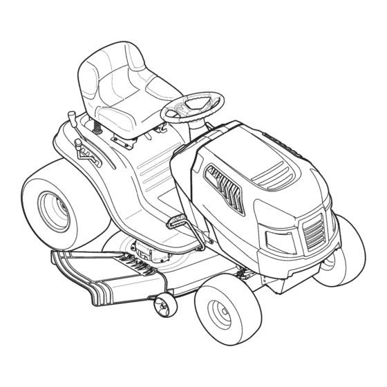
LAWN TRACTOR
19.5 HP, Variation Speed
42" Deck
Model No. 247.288843
• Espanol,
P. 60
This product
has a low emission
engine
which operates
differently
from
previously
built engines.
Before
you start the engine,
read and
understand
this Operator's
Manual.
Before
using this equipment,
read this manual
and follow
all safety
rules and operating
instructions.
For answers
to your questions
about
this product,
Call:
1-800=659=5917
Craftsman Tractor Help Line
7 am = 7 pm CT, Mort. =Sun.
Sears Brands
Management
Corporation,
Hoffman
Estates,
IL 60179 U.S.A.
Visit our website:
www.craftsman.com
Form No.769-06421D
(November 28,2012)
Advertisement
Table of Contents

Related Manuals for Craftsman 247.288843


Summary of Contents for Craftsman 247.288843
- Page 1 Call: Before using this equipment, 1-800=659=5917 read this manual and follow all safety rules and operating Craftsman Tractor Help Line instructions. 7 am = 7 pm CT, Mort. =Sun. Sears Brands Management Corporation, Hoffman Estates, IL 60179 U.S.A.
- Page 2 Withproofofpurchase, a newcastironfrontaxlewillbe supplied freeofcharge. WARRANTYSERVICE Forwarrantycoveragedetails to obtainfree repairor replacement, c arl 1-800-659-5917 or visitthe web site:www.craftsman.com in all casesabove, if part repairor replacement i s impossible, t he riding equipment w ill be replacedfreeof chargewith the sameor an equivalent model.
- Page 3 This machinewas builtto be operatedaccordingto the safeopera- This symbolpointsout importantsafetyinstructionswhich,if not tion practicesin this manual.As with anytype of powerequipment, followed,couldendangerthepersonalsafetyand/orpropertyof carelessnessor error on the partof the operatorcan resultin serious yourselfand others. Readand followall instructionsin this manual injury.This machineis capableof amputatingfingers,hands,toes beforeattemptingto operatethis machine.Failureto complywith and feet and throwingdebris.Failureto observethe followingsafety these instructionsmay resultin personalinjury.Whenyou seethis...
- Page 4 SLOPE OPERATION • Slowdownbeforeturning.Operatethe machinesmoothly.Avoid erraticoperationand excessivespeed. Slopesare a majorfactorrelatedto loss of controland tip-over Disengageblade(s),set parkingbrake,stopengine and wait until accidentswhichcan result in severeinjuryor death.All slopes require the blade(s)come to a completestop beforeremoving grass extra caution.If youcannot back up the slopeor if youfeel uneasyon catcher,emptyinggrass,uncloggingchute,removinganygrass or it, do not mowit.
- Page 5 CHILDREN SERVICE Tragicaccidentscanoccur ifthe operatoris notalert to the presence SafeHandlingof Gasoline of children.Childrenare often attractedto the machineand the mowing Toavoidpersonalinjury or propertydamageuse extremecarein activity.They do notunderstandthe dangers.Neverassumethat handlinggasoline.Gasolineisextremelyflammableand the vaporsare childrenwill remainwhereyou last sawthem. explosive.Seriouspersonalinjury canoccur whengasolineis spilled • Keepchildrenout of the mowingareaand inwatchfulcare of a on yourselfor your clotheswhich can ignite.
- Page 6 General Service • Donot changethe enginegovernorsettingsor over-speed the • Never run anengine indoors orina poorly ventilated area. Engine engine.The governorcontrolsthe maximumsafe operatingspeed exhaust contains carbon monoxide, anodorless, and deadly gas. of the engine. • Before cleaning, repairing, orinspecting, make c ertain the Maintainor replacesafetyand instructionlabels,as necessary.
- Page 7 SAFETY SYMBOLS This pagedepictsand describessafety symbolsthat may appearon this product. Read,understand,and follow all instructions on the machine beforeattemptingto assembleand operate. READ THE OPERATOR'S MANUAL(S) Read, understand, and follow all instructions in the manual(s) before attempting to assemble and operate DANGER-- ROTATING BLADES Never carry passengers.
- Page 8 15° Slope 15° Slope (OK) (TOO STEEP) '_. _ Figure 1 Figure 2 15° dashed line USETHISSLOPE GAUGE TODETERMINE IF A SLOPE IS TOOSTEEPFORSAFEOPERATION! To checkthe slope, proceedas follows: Removethis pageand fold along the dashedline. Locatea verticalobject on or behindthe slope (e.g. a pole, building,fence, tree, etc.) 3.
- Page 9 iMPORTANT: Y ourtractoris shippedwith motoroil in theengine. Shipping Brace Removal However, y ou MUSTcheckthe oil levelbeforeoperating.Referto the Service& Maintenancesectionfor instructionson checkingtheoil level. Makesurethe ridingmower'sengineis off, removetheignitionkey, Attaching the Battery Cables and set the parkingbrakebeforeremoving the shippingbrace. Refer Ito the Operationsectionfor instructionson howto set the parking lbrake.
- Page 10 Adjusting the Seat Toadjust the positionof the seat,pull up and hold the seat adjustment lever.Slide the seatforwardor rearwardto thedesiredposition;then releasethe adjustment l ever.Makesure seatis lockedintopositionin a seat-stopbeforeoperatingthe tractor.See Figure5. Beforeoperatingthe tractor,makesurethe seat is engagedin a seat-stop.Engagethe parkingbrake.Standbehindthe machineand pull backon seatuntil it clicks intoplace. Figure3 Placethe steeringwheelcap overthe centerof the steeringwheel and pushdownwarduntil it "clicks"into place.
- Page 11 Seat A djustment L ever Deck Lift Lever Brake Pedal NOTE: Any referencein this manualto the RIGHTor LEFTside of the tractoris observedfrom operator'sseat positionfacingforwardtowardsthe frontof tractor. Meets ANSi S afetyStandards Craftsman T ractors conform to the safetystandard ofthe American National S tandards I nstitute(ANSI).
- Page 12 ParkingBrakeLever SeatAdjustmentLever Tosetthe parkingbrake:Fullydepress t he brakepedal.Movethe Theseatadjustment l everislocatedbelowthe front/left of the seat.Thelever parkingbrakeleverintothe parkingbrakeposition.Release t he allowsforadjustment o f the foreandaft positionof the seat.Refer t o the Assembly brakepedalto allowthe parkingbrake to engage. sectionof the manualformoredetailedinstructions foradjustingthe seatposition. Torelease the parkingbrake: D epress t he brakepedalandthe Auto-drivepedal parkingbrakeleverwill moveout of the parkingbrakepositionon...
- Page 13 Gasand Oil Fill-up IMPORTAfl# Your t ractorisshippedwith motoroil intheengine.However, you MUST check the oil levelbefore operating. B ecareful n ot tooverfill. Forinstructionsonhowto check the engineoil,referto Checking TheEngine Oilin the Service a ndMaintenance s ectionof thismanual. Gasoline Thegasoline tank islocatedunderthe hood.Donotoverfill. Useextreme carewhen handling gasoline.Gasolineisextremelyflammable andthe vaporsareexplosive.Neverfuel machineindoors or while the engine ishot or running.
- Page 14 Theenginewill automatically s hut off if the PTO (Blade Engage) l everis Setting the Cutting Height movedintothe engaged (ON)positionwith the shift leverinReverse. Select t he heightpositionof the cuttingdeckbyplacingthe decklift leverin Ignition Switch anyof thedifferentcutting heightnotches on the rightsideof the fender. Adjustthe deckwheelssothatthey arebetweenl_-inchand1/2-inch a bove Theignition switchis activated to startthe engine.Insertkeyinto the ignition the groundwhenthe tractorison asmooth, f lat surface suchasadriveway.
- Page 15 DrivingTheTractor DoNOThold the key in the START positionfor longerthan ten seconds at a time. Doingsomay causedamageto your engine's electric Avoidsuddenstarts, excessive speedandsuddenstops. starter. Afterthe enginestarts,deactivate the chokecontrol a ndplace the throttle Donot leavethe seatof the tractor without first placingthe PTO (Blade control i n the FAST p osition.
- Page 16 DrivingOnSlopes Mowing Referto the SLOPE GAUGE i nthe SafetyInstructions sectionofthe manual t o help determineslopes whereyoumayoperatethistractorsafely. Tohelpavoid bladecontactor athrown object injury, keepbystanders, helpers,children andpets at least 75; f eet from the machinewhile it is in operation. Stopmachineif anyoneentersthe area. Donot mow on inclines w ith a slope inexcess of 15degrees(a riseof approximately2-112 feet every 10feet).
- Page 17 MAINTENANCE SCHEDULE Beforeperforming anytype of maintenance/service, d isengageall controls Follow the maintenance s chedule givenbelow.Thischartdescribes s ervice andstop the engine.Wait until all moving partshavecometo a complete guidelines only.Use the Service Logcolumn to keeptrackofcompleted stop.Disconnect sparkplug wire andgroundit againstthe engine to prevent maintenance t asks.Tolocate the nearestParts &...
- Page 18 ChangingEngine Oil Engine Maintenance Theengineoil shouldbechanged in the first 5hoursandthenevery50 hours or Checking the Engine Oil onceaseason. Tochange the engineoil,proceed asfollows: Onlyusehighqualitydetergentoil ratedwith APIservice classification S F, S G, With engineOFF but still warm,disconnect sparkplugwire andkeepit away SH, o r SJ. S elect t he oil'sSAE viscosity gradeaccording to the expected operating from sparkplug.
- Page 19 Fuel Filter Air (:leaner Theairfilter systemuses acylindrical c artridge. Remove t he fasteners CA) andthe air filter cover(B).SeeFigure 13. Gasolineanditsvapors areextremely flammable andexplosive.Fireor explosioncancause severe burnsor death. Toremove the filter (C),lift the endof the filter andthenpullthe filter off the intake (D). Keep gasoline awayfrom sparks, o penflames,pilot lights,heat,andother Toloosen debris,gentlytap the filter onahardsurface.
- Page 20 Muffler re-installingthe battery,alwaysconnect t he POSITIVE (Red) w ire to its terminal first, followedbythe NEGATIVE (Black) w ire. Becertainthat the wiresareconnected to the correct t erminals; r eversing them couNchange the polarityandresultin damage to yourengine'salternatingsystem. Temperature o f muffler andnearbyengine areasmayexceed150 ° F(65°Q. Avoidcontactwith theseareas.
- Page 21 Adjustments Side to Side Ifthe cuttingdeckappears to be mowingunevenly, asideto sideadjustmentcanbe performed. A djustif necessary a sfollows: Neverattempt to makeany adjustmentswhile the engine isrunning,except With the tractorparkedonafirm, levelsurface, p lacethe decklift leverin where specifiedin the operator's manual. the second from the top notch(second highestposition)androtateboth bladessothat theyareperpendicular with the tractor.
- Page 22 Cutting Deck Removal To remove the cutting deck, proceed as follows: Bow-Tie Clip Place the PTO (BladeEngage) l everinthe disengaged (OFF) p ositionand engage the parkingbrake. Lowerthe deckbymovingthe decklift leverinto the bottomnotchon the rightfender. Remove t he self-tappingscrew (A)thatsecures the belt-keeper r odfrom around the tractor'sPTO pulley,then remove the belt keeperrod(B).See Figure 18.
- Page 23 Connect t he otherendof the cableto the (positive+) postof thejumper battery. Connect t he second cable(negative -) to the otherpostof thejumper battery. Connect t he otherendof the negativecableto the engineblockofthe tractor,awayfrom the battery.Attachto anunpaintedpartto assure agood connection. If the jumperbattery isinstalledon avehicle (i.e. car,truck),do NOT start the vehicle'senginewhen jump starting your tractor.
- Page 24 Cutting Blades If the cutting edge of the bladehaspreviously beensharpened,or if any metalseparationispresent,replace the bladeswith newones. Shutthe engineoff andremoveignitionkeybeforeremoving the cutting blade(s)for sharpeningorreplacement. P rotectyourhandsbyusingheavy [g oveswhen graspng the bade. A poorly balancedbladewill causeexcessive vibration, maycausedamageto the tractor and/or resultin personal injury. Periodicallyinspect t he bladeand/or spindlefor cracksor damage, Testthe blade'sbalanceusingabladebalancer.
- Page 25 Whileholdingthe belt andpulleytogether,rotatethe pulleyto the left. Changing the TransmissionDrive ieit Continue holdingandrotatingthe pulleyandbelt untilthe belt isfully rolled NOTE: Several components must be removed and special tools (i.e. air/ into the PTO pulley. impact wrench) in order to change the tractor's drive belt. Contact the nearest Parts &...
- Page 26 Neverstore lawn tractor with fuel in tankindoors or in poorlyventilated areaswhere fuel fumes may reachanopen flame, spark,or pilot light ason a furnace,water heater, clothesdryer,or gasappliance. PreparingTheEngine DrainingThe Fuel IM PORTANT: Fuel l eft inthe fueltank duringwarmweatherdeteriorates a nd Locate the fuel filter,whichis located on the left sideofthe engine,andmay will cause serious startingproblems.
- Page 27 Enginefails to start PTO/BladeEngageleverengaged. Placeleverin disengaged(OFF) position. Parkingbrakenotengaged. Engageparkingbrake. Sparkplugwire(s) disconnected. Connectwire(s) to sparkplug(s). Throttle/Chokecontrollevernot in correct PlaceThrottle/Chokeleverintothe FASTposition. startingposition. Chokenotactivated MovetheThrottle/Chokeleverintothe Choke position. Fueltank empty,or stale fuel. Filltank with clean,fresh (less than 30 days old) gas. Blockedfuel line. Replacethe fuel line and replacefuel filter. Faultysparkplug(s).
- Page 28 Pa+tsavmilahle a t mosl Sears RetailSt+res amdSe+vi+e 777D18561 Ce_+e_or_.II I-SOO._+-PART(7_TS) ifW" wan+ thepart sent_irectlvto yo_Phome. ×+_o3 Spec_f+c tractor attachments for yo,r Craftsman tm_tor_va+lableat Se_rs St_es an_ Se_v_e Centers. See _elo_formhe_un+vers_l a nac_ments a lso avml_le. Dascriptialm Stock M.lch Kit 33788...
- Page 29 This page intentionally left blank. Use this page to make any notes regarding your tractor.
- Page 30 Craftsman IViodel 247.288843 14" 50/_...
- Page 31 Craftsman Model 247.288843 Part No. Description Part No, Description Ref, Ref, 925-I 649 Bulb Socket 741-0587 Steering Column Bearing 712-04063 683-04619A-4044 Nut, Hex Flange Lock, 5/16-18 Hood Assembly 783-06785A-0637 710-04484 Screw, 5/16-18 x .750 Steering Support Bracket 710-0599 783-06811-0637 Dash Hex Washer Screw, 1/4-20 x .500...
- Page 32 Craftsman IViodel 247.288843...
- Page 33 Craftsman IViodel 247.288843 Ref. Ref, Part No. Part No, Description Description 683-04155A-0637 756-04196A Shaft,Lift EngagementPulley 712-04065 747-04857 Nut,Hex FlangeInsert Lock,3/8-16 Belt KeeperRodAssembly 714-04040 710-04484 Bow-TiePin, 91, RH Screw,Hd.Tapp, 5 /16-18x .75 716-0106A 683-04195-0637 E-ring,.625Shaft Support BracketAssembly 720-0311 683-04649A-0637 Grip,Handle RiderFrameAssembly...
- Page 34 Craftsman IViodel 247.288843 38._ 24 _ ....
- Page 35 Craftsman IViodel 247.288843 Part No. Description Part No, Description Ref, Ref. 617-04094 683-0128B-0637 GearAssembly, S teering PivotBar AxleAssembly 710-0643 Screw,5/16-18,1.00,Gr5,Lock 710-04484 Screw,5/16-18,0.750 712-04065 710-1309 Screw,Mach,5/16-18,0.750 Nut, FlangeLock, 3/8-16,GrF 710-0514 714-0162 Pin, Cotter,5/32, 1.25 HexHead Screw,3/8-16x 1.00 914-0474 710-3180 Pin, Cotter,1/8 x 0.75 Screw,5/16-18,1.75,Gr5...
- Page 36 Craftsman Model 247.288843...
- Page 37 Craftsman Model 247.288843 Part No. Description Ref, 710-04482 Hex Flange Bolt, 3/8-16 x .875 710-04484 Screw, Hd.-lapp, 5/16-18 x .75 712-3004A Flange Lock Nut, 5/16-18 925-05013 Seat Safety Switch 757-04144 Seat 926-0154 Push Mount Cable Tie 732-04035 Spring, Compress., 1.28 x 3.125 732-04563 Spring, Compress., .68 x 1.065 x .055...
- Page 38 Craftsman IViodel 247.288843...
- Page 39 Craftsman IViodel 247.288843 Ref. Description Part No. 683-04549-0637 MufflerShieldAssembly 710-0227 Screw,AB #8-180.500 710-04683A TapScrew,3/8-16 1.000 710-0642 TapScrew,1/4-200.750 710-1314A Screw,SocketHead,5/16-18 x .750 712-0271 Sems Nut, 1/4-20 BS-692236 ExhaustGasket 725-0157 CableTie,3/16 X .05 X 7.4 726-0205 HoseClamp,.490 Dia. 731-05628 Oil DrainSleeve 751-10349...
- Page 40 Craftsman Model 247.288843...
- Page 41 Craftsman Model 247.288843 Description Description Ref, I Part No. Ref, I Part No. 731-04602 918-04566 Sleeve, .758 X .821 X 3.3125 Dr Assembly, Autodrive Lt-5 731-04604 683-04606 Sleeve, .758 X .821 X 2.4375 Auto-drive Bracket Assembly 731-06330 783-06662 Idler Bracket Assembly...
- Page 42 Craftsman IViodel 247.288843 "50 33 ._ "45 28._ 33. t 10..
- Page 43 Craftsman Model 247.288843 Description Description Ref. I Part Number Ref. I Part Number 941-0919A 918-04822A Bearing, Ball, .787id x 1.85 Odx.551 Spindle Ass'y, Pulley, 6.3 Dia 683-0254B-0637 936-0344 Washer, Flat, .385 X 1.0 X .030 Bracket Ass'y, Deck, Hanger LH...
- Page 44 Craftsman Engine Model 31P677=0912=G5 For Model 247.288843 48 SHORTB LOCK 110580PERATOR'SMANUAL] 11329REPLACEMENTENGINEI 11330REPAIRMANUALI :: ....,¢.32 ..584684 : 1264 :_i 691 (_, 1044 !_ 146 r b1-/ 307 _ 7414 7s8i 1270 404 _ 759 i 1o27 524 C>...
- Page 45 Craftsman Engine Model 31P677=0912=G5 For Model 247.288843 1026 1026A _¢_ 1022 1029 914 _ Assemblies include all parts shown in frames.
- Page 46 Craftsman Engine Model 31P677-0912-G5 For Model 247.288843 108_ 13o I 217_ 987 ::_1 1091 [ S°"_ 276 _9) .._s/_ 1127 _} " 601 _,_ Assemblies include all parts shown in frames.
- Page 47 Craftsman Engine IViodel 31P677=0912=G5 For IViodel 247.288843 1036E MISSIONS LABEL 1040 305A 305B 1070 1005 1044 ® 1051 783@ Assemblies include all parts shown in frames.
- Page 48 Craftsman Engine Model 31P677=0912=G5 For Model 247.288843 1119 8Ol _ _,_,y _-.< :::-_.\ K__, _ ,,:.Y 188 '_@ © Assemblies include all parts shown in frames.
- Page 49 Craftsman Engine Model 31P677=0912=G5 For Model 247.288843 121 CARBURETORO VERHAULK IT 987(_ 1266A _<=-) 358 ENGINEG ASKET SET <_ 1095 VALVEG ASKET SET 5" 1022 Assemblies include all parts shown in frames.
- Page 50 Craftsman Engine IViodel 31P677=0912=G5 For IViodel 247.288843 Ref, Ref. Part No. Part No. Description Description 796010 696136 Valve-Float Needle Cylinder Assembly 399265 695419 Valve-Choke Kit-Bushing/Seal (Magneto Side) 391086s 699733 Seal-Oil (Magneto Side) Jet-Main (Standard) 697188 843099 Sump-Engine Jet-Main (High Altitude)
- Page 51 Craftsman Engine IViodel 31P677=0912=G5 For IViodel 247.288843 Ref. Ref. I Part No. Description Part No. Description 796006 Shield-Cylinder 692407 Seal-Governor Shaft 691693 Screw (Cylinder Shield) 791680 Screw (Drive Cap) 693551 Motor-Starter 690959 Pin-Locating 690323 Screw (Starter Motor) 691224 Clip-Wire 796308...
- Page 52 Craftsman Engine IViodel 31P677=0912=G5 For IViodel 247.288843 Part No. Description Ref, 1027 492932s Fitter-Oil 1029 691751 Arm-Rocker 1034 690822 Guide-Push Label-Emissions (Available from a 1036 Briggs & Stratton Authorized Dealer) 1040 699852 Plate-Trim 1044 698139 Screw (Flywheel) 1051 691265 Ring-Retaining...
- Page 53 Esta pagina se dej6 intencionalmente en blanco. Utilice esta pagina para tomar notas acerca de su tractor.
- Page 54 Esta pagina se dej6 intencionalmente en blanco. Utilice esta pagina para tomar notas acerca de su tractor.
- Page 55 Look For Relevant Emissions Durability Period and Air index information On Your Engine Emissions Label Engines that are certified to meet the California Air Resources Board (CARB) Tier 2 Emission Standards must display information regarding the Emissions Durability Period and the Air Index. Sears Brands Management Corporation makes this information available to the consumer on our emission...
- Page 56 (Thispage applicablein the U.S.A.and Canadaonly.) Sears Brands Management Corporation (Sears), the California Air Resources Board (CARD) and the United States Environmental Protection Agency (U.S. EPA) Emission Control System Warranty Statement (Owner's Defect Warranty Rights and Obligations) EMISSIONCONTROL WARRANTY COVERAGEISAPPLICABLE TO CERTI- YEAR 1997AND LATERENGINES WHICHARE PURCHASED AND USED FIEDENGINESPURCHASEDIN CALIFORNIAIN 1995ANDTHEREAF- ELSEWHERE IN THE UNITEDSTATES (ANDAFTERJANUARY1,2001 IN...
- Page 57 FEDERAL and/or CALIFORNIA EMISSION CONTROL W ARRANTY S TATEMENT YOUR WARRANTY RIGHTS ANDOBLIGATIONS MTD Consumer Group Inc, the United States Environmental Protection Agency (EPA), and, for those products certified for sale in the state of California, the California Air Resources Board (CARB) are pleased to explain the emission (evaporative and/or exhaust) control...
- Page 58 10. Add-on o rmodified parts t hatare not e xempted bythe AirResources Board m ay not b eused. The use ofany non-exempted add-on o r modified parts b ytheultimate purchaser willbegrounds fordisallowing awarranty claims. MTD Consumer Group I nc willnotbeliable t o warrant failures ofwarranted parts c aused bytheuse ofanon-exempted add-on o rmodified part.
- Page 59 Congratulations on making a smart purchase. Your new Craftsman® product is designed manufactured for years of dependable operation. But like all products, it may require repair from time to time. That's when having a Repair Protection Agreement can save you money and aggravation.
- Page 60 SERVlCIODEGARANT{A Paradetallesde la coberturade garantiaobtenerla reparaci6no reemplazo,Ilameal 1-800-659-5917 o visite el sitio web: www.craftsman.com Entodosloscasos,sisepartede la reparaci6n o reemplazo e simposible, el equipo de equitaci6n sereemplazar& gratuitamente conelmismoo equivalente. Todos losde la anterior g arantia esnulasiseutiliza esteequipo de conducci6n m ientras queproporciona s ervicios c omerciales o Sialquila a otrapersona.
- Page 61 Esta rn_.quina r ue construidapara seroperadade acuerdocon La presenciade este sirnboloindicaque setrata de instrucciones las reglasde seguridadcontenidasen este manual.AI igualque irnportantesde seguridadque se deben respetarpara evitar concualquiertipo de equipo rnotorizado, u n descuidoo error por poner en peligrosu seguridadpersonaly/o materialy la de otras partedel operadorpuedeproducirlesionesgraves.Esta rn_.quina personas.Lea y siga todaslas instruccionesde este manualantes es capazde arnputarrnanosy piesy de arrojarobjetoscon gran...
- Page 62 • Nuncadeje la rn_.quina e n funcionarniento s invigilancia.Apague • Vayaa bajavelocidad.ElijaunavelocidadIosuficienternente b aja, siernprelascuchillas, c oloqueel frenode rnano,detengael motory de rnodoque no tengaque detenerse o hacercarnbios rnientras retirela Ilaveantesde bajarsedel vehiculo. est,. sobrela pendiente. L osneurn_.ticos p odrianperdertracci6n sobrelaspendientes aQn cuandolosfrenosfuncionaran apro- •...
- Page 63 • Paraevitaraccidentes al operaren rnarcha atr_.s, s iernpre desengan- • Apaguetodos loscigarrillos,cigarros,pipasy otrasfuentesde chelascuchillas antesde colocarrnarcha atr_.s. S iest,. instalado, cornbustidn. el "ModoPrecaucidn Marcha Atr_.s" ( hojasde operarla rn_.quina, • Nuncacarguecombustibleen la rn_.quina en un espaciocerrado. rnientras quelospaseosa la inversa) n o debeutilizarse cuandohay •...
- Page 64 NO MODIFIQUE EL MOTOR • Reviselos pernosde montajede la(s) cuchilla(s)y del motora intervalosfrecuentespara verificarque est6n bien apretados. Paraevitarlesionesgraveso la muerte,no modifiqueel motorbajo Adem_.s, i nspeccionevisualmente la(s) cuchilla(s)en buscade ningunacircunstancia. S i cambiala configuraci6ndel reguladordel daSos(por ejemplo,desgasteexcesivo,abolladuras,rajaduras, motorel motor puededescontrolarse y operara velocidadesinsegu- etc.).
- Page 65 SJlVlBOLOS DE SEGURIDAD Esta p&ginarepresenta y describela seguridadlos simbolosque puedenpareceren este producto.Lea,comprenda,y sigatodas instrucciones en la m_quinaantesprocurarpara reuniry operar. LEA EL MANUAL(S) DEL OPERADOR leido, entienda, y siga todas las instrucciones en el manual(s) antes de procurar montar y funcionar PELIGRO-- DE EL CORTE DE PIE Nunca transporte pasajeros.
- Page 66 15° Pendiente I5 ° Pendiente (DEMASIADO ESCARPADO) (ACEPTAR) • Figura1 Figura 2 "'" USO DE ESTE PENDiENTE DE CALIBRE PARA DETERrvIINAR SlUNA PENDIENTEES DEIVlASIADO E SCARPADO PARA UNA OPEBACION SEGURA! Para comprobar la pendiente, haga Io siguiente: Borrar esta p_gina y doble a Io largo de la linea discontinua. Localizar un objeto vertical sobre o detr_.sde la pendiente (un poste, un edificio, una valla, un _.rbol,etc.) Alinee cada lado de pendiente de calibre con el objeto vertical (consultar Figura 1 and Figura 2 ).
- Page 67 ENVlO BRACE ELllVIINACION IMPORTANTE: Su tractorseentregaconaceite de motoren eJ motor.Sin embargo,debe cornprobarel nivelde aceiteantes de operar.Consultela secci6nde Servicioy Mantenirniento para obtener AsegQrese de que el motordel tractorcortacesped es, retirela Ilave instrucciones sobrela cornprobaci6n del nivelde aceite. de encendido,y ponerel frenoantesde quitarla Ilavede envio. CONEXION DE LOS CABLES DE LA BATERIA...
- Page 68 Coloquela arandela(con la parteahuecadahaciaabajo) sobreel Conecte el mazodecablesenel interruptorde seguridaddelasiento volantey seguracon el tornillohexagonal. W ase la figura.3. en la parteinferiordel asiento,como se muestraen B de la Figura NOTA: E l tractorno funciona conel cabledealimentacidn desconectado. Ajuste del asiento Paraajustarla posici6ndel asiento,firelohaciaarriba y sostengala palancade ajustedel asiento.Desliceel asientohaciaadelanteo haciaatr_.sa la posici6ndeseada;luego sueltela palancade ajuste.
- Page 69 Levantela palancade la cubierta NOTA:Cualquierreferencia hechaen este manualal lado DERECHO o IZQUlERDOdel tractordebeentenderse tal como seobservadesde la posici6ndel operador. Curnple con los est_ndares de seguridad de ANSI Lasm_.quinas quitanievede Craftsman cumplen conlosest_.ndares de seguridad delinstituto estadounidense d e est_.ndares nacionales ( ANSI).
- Page 70 FRENO DE ESTACIONAIVllENTO PALANCA DE AJUSTE DEL ASIENTO Paraajustarel frenode estacionarniento: completa- La palancade ajustedel asientose encuentradebajode la parte rnenteel pedalde freno.Moverla palancadel frenode frontal/izquierda del asiento.La palancaperrniteel ajuste de la parte estacionarniento en la posici6ndel frenode estaciona- delanteray la posici6nlongitudinal d el asiento.Consultela secci6nde rniento.Suelteel pedal del frenopara que el frenode la Asarnbleadel manualparaobtenerinstruccionesrn_.s detalladas estacionarniento a participar.
- Page 71 • Llenarel dep6sitode combustibleal aire libreo en lugar bien LA PALANCA ventilado. CAMBIO • NuncaIleneen excesoel dep6sitode combustible.Lleneel La palancade carnbiosest,. tanqueno rn_.s de 1/2 pulgadapor debajode la basedel cuello situadaen el lado izquierdo d e la del tap6nde carga, paradejar espaciopara la expansi6ndel defensay tienetres posiciones, combustible.
- Page 72 INTERRUPTOR DE ENCENDIDO El interruptor de encendidose activaal arrancarel motor.Insertela Evite lesiones personales graves o la muerte Ilaveen el interruptor de encendidoy girara la derechaa la posici6n • En laspendientesconduzcahaciaarriba y haciaabajo, START.Sueltela Ilaveen la posici6nde encendidouna vez que el no de forrnatransversal.
- Page 73 El frenode estacionarniento del tractor. AJUSTE DE LA ALTURA DE CORTE Activeel controldel estrangulador. Seleccionelaposici6ndealturadela plataforrnadecorternediantela Girea la izquierda l a Ilavede encendidoa la posici6ninicial. colocaci6nde la palancade levantarla cubiertaen cualquierade Despu_sde que el motorarranque,suelte la tecla. Se volver_, a la los diferentesrnuescasalturade corte en el lado derechode la ON(Normalo cortarel c_sped)posici6n.
- Page 74 INVOLUCRAR A LOS BLADES se desplazar_, en la direcci6ndeseadasobrela basede la posici6nde la palancade carnbios. Participaci6n de la tornade fuerza(BladeEngage)lastransferencias de El tractorde cespedes Ilevadoa una paradapor la liberaci6nde energiaa la plataforrna de corteo de otto tipo(disponibiepot separado) la unidadde pedal y luego oprirnirel pedalde freno. los archivosadjuntos.Paraparticipar de las hojas,haga Iosiguiente: AI pararel tractor,por cuaiquierrnotivo,rnientrasqueen una superficie Moverla palancade controldel aceleradora la r_.pida (conejo)la...
- Page 75 CORTAR FAROS • LasI_.mparas e st_.nONcuandoel motordel tractorse est,. ejecutando. Paraayudara evJtarel contactocon la cuchJlla o una lesJ6n en • Lasluces se apagacuandola Ilavede contactose muevea la el objetolanzado,Mantenga a losespectadores,losayudantes, posici6nSTOE los niSosy las mascotaspor Io menos75 piesde distanciade la m_.quina mientrasest,.
- Page 76 LISTA DE iVlANTENIIVllENTO Antesde realizarcualquiertipodel rnantenirniento/servicio, suelte Siga la lista de rnantenirniento dadaabajo.Esta carta describepautas todoslos rnandosy pareel motor.Esperehasta que todaslas partes de servicios61o. U sela colurnnade Troncode Servicioparaguardarla de rnovirniento hayanvenidoa una paradacornpleta.Desconecteel pista de tareasde rnantenirniento cornpletadas. alarnbrede bujiay b_.selo contra el motor para prevenirel cornienzo Localizarel rn_scereanoCharnusca el Centrode Servicio o pro- involuntario.
- Page 77 iVlANTENIIVllENTODEL MOTOR Comprobar el aceite del motor No Ilenedernasiado. L lenadoexcesivode aceite puedeprovocarque $61oel uso de aceite de alta detergenteseevalu6la calidadcon la el motor no ernpezar, d iffcilde partida,o furnarmotor.Si rn&sde la clasificaci6nde servicioAPI SF,SG,SH, o SJ. Seleccioneel aceite rnarcaFULLen la varilla,el aceitede drenajepara reducirel nivelde aceite en FULLrnarcaen la varillade rnedici6n.
- Page 78 • Antes dereernplazar elfiltro decombustible, vaciar eltanque de LIMPIADOR DE AIRE combustible segQn lasinstrucciones deabajo. El sisternade filtro de aire utiliza un cartuchocilindrico.Esternodelo • No fuga decombustible cuando elmotor est,. caliente. Deje q ue tarnbi_nincluye un pre-lirnpiador q ue se puedenlavary reutilizar. elmotor detiernpo adecuado para enfriar.
- Page 79 Silenciador IMPORTANTE: Sial quitarla baterfapor cualquierraz6n,desco- necteel cablenegativo(Negro)es el cable de la terminalen primer lugar,seguidopot el positivo(rojo)de alarnbre.Cuandovuelvaa Ternperatura del silenciadory _.reas cercanasdel motor podr_, s er instalarla baterfa,conecteel positivo(rojo)de alarnbrede su terminal superiora 150 0F (65 °C). Eviteel contactocon estas_.reas. en primerlugar,seguidoporel negativo(cableNegro).AsegQrese de que loscables est_.n conectadosa losterrninalescorrectos,inversi6n Inspeccioneperi6dicarnente el silenciador,y reernplazar s i es...
- Page 80 LIMPIEZA DE LAS MAQUINAS Y LA CUBI- La partefrontalde la cubierta debeser de 1A pulgadasy 3/8-pulgada inferiora la parte traserade la cubierta.Ajuste sies necesarioIo ERTA siguiente: Cualquiercombustibleo aceitederrarnado en la rn_.quina d ebe ser Coneltractorestacionadoen unasuperficiefirrney nivelada, c oloque borradode inrnediato. NOperrnitaque los desechosque se acurnulan la palancade elevaci6nde la plataforrna en la segundaa la alrededorde lasaletas de refrigeraci6n del motoro en cualquierotra prirneracategoria(segundaposici6nrn_.s alta), y gire la hoja Io...
- Page 81 Bajola cubiertarnoviendola palancade elevaci6nde cubiertaen la rnuescaen la parteinferiordel guardabarrosderecho. Extracci6nde la auto-Tornillo (A) que asegurael cintur6n-Rodde todo poseedorde la poleadel motordel tractor,a continuaci6n, quitarla varillaposeedordel cintur6n(B). Wase la figura. 11. Note: Haga una nota mental de Io agujero al otto extremo de la cinta-Rod poseedor se inserta en los prop6sitos...
- Page 82 Bow-TieClip PTOCable Figura19 Retirela pajaritachavetagarantizarla barraestabiNzadora de Figura21 cubiertaa cubierta.DesNce la barrade levantarla cubiertade la soldadurade rnontajeen la cubiertacomose ve en lafigura. 20. N EUiMIJ.'I'ICOS Nosobrepasarnuncala presi6nrn_.xirna de infladoque apareceen /<_ <iz ; ;:J_c_ <ci:i,) cc;c) cc;;; <; d;U:;_b la paredlateralde la Nanta. La presi6n de los neumaticos recomendada...
- Page 83 Conecteel otroextrernodel cablea la (positivo+)despu_sde la bateriade puente. Inspeccione peri6dicarnente la hojay / o husillode grietas o da_os, Conecteel segundocable(negativo-) para el otropuestode la sobretododespu_sde haberIlegadoa un objetoextra_o.No bateriadel puente. Ihaga funcionarla rn_.quina hastaque se sustituir_.n loselernentos Hacerla conexi6nfinal en el bloquedel motordel tractor,lejos _da_ados.
- Page 84 Paracarnbiaro sustituirla cinta de la cubiertaen sutractor,haga Io siguiente: Si el filo de la hoja ha sidopreviarnente afilado,o si cualquiersepara- Quite la cubiertacornose indicaanteriorrnente en esta secci6n. ci6nde metalest,. presente,sustituirlashojaspor otras nuevas. Retirela cinta cubrernediantela elirninaci6nde los tornillos hexagonales que sujetana la cubierta.Wase la figura.25. Tarnbi_npuedeser necesarioaflojarla tuercahexagonal d e la polea tensoraa la izquierdapara obtenerel cintur6nalrededorde Unahoja rnal equilibrada causar_, e xcesivavibraci6n,puedecausar...
- Page 85 Nuncaalmacenetractor de c_sped con combustibleenel tanque en un espaciocerradooen _reasconpocaventilaci6n, dondelosgases del combustiblepuedanalcanzarelfuego, chispas o una luzpiloto comola que tienen algunoshomos,calentadoresde agua,secadores d e ropa oalgun otro dispositivoagas. Extraiga labujiay viertauna(1)onzadeaceiteparamotorporelorifido Preparad6ndei motor delabujiaeneldlindro.Haga girarel motorvariasveces paradistribuirel [M PORTANTE: El c ombustible quequedaen eltanquecuandohatecaiorse aceite.
- Page 86 El motor no arranca Perilla de potencia de arranque (PTO) Coloque la perilla en la posici6n de desconexi6n conectada. (OFF). No est,1 colocado el freno de mano. Coloque el freno de mano. Se ha desconectado el cable de las bujias. Conecte el cable alas bujias.
- Page 87 Busque el periodo de duraci6n de emisiones importantes yla informaci6n de clasificaci6n de aire en la etiqueta de emisiones de su motor Los motores cuyo cumpiimiento con los estAndares de emisi6n Tier 2 de la Comisi6n de Recursos Ambientales de California (CARB) est6 certificado deben exhibir la informaci6n relacionada con el periodo de duraci6n de ias emisiones y la clasificaci6n de aire.
- Page 88 (Esta p_.ginase aplica s61oen EE.UU. y Canada.). Sears Brands Management Corporation, el Consejo de Recursos Ambientales de California (CARB) y la Agencia de Protecci6n Ambiental de los Estados Unidos (EPA) Declaraci6n de garantia del sistema de control de emisiones (derechos y obligaciones de la garanfia de defectos del propi= etario)
- Page 89 DECLARACION FEDERAL y/oDECALIFORNIA SOBRE GARANTJAS EN EL CONTROL DE EIVIISIONES SUS DERECHOS Y OBLIGACIONES EN CUANTO A LA GARANTJA MTDConsumerGroupInc, laAgencia de Protecci6nMedioambiental d e los EstadosUnidos(EPA),y para aquellosproductoscertificadosparasu ventaen el es- tadode California,el Departamento de los Recursosdel Aire de California(CARB)secomplacenen explicarla garanfiaque cubre al sistemade control (ECS)de emisiones(evaporativasy/o de escape)de su equipoy motor(motor de equipos de exteriores)de encendidopot chispa paratodo terreno,peque_o,de exteriores del a_o2006 y a_osposterioresEn California,losnuevosmotoresde equipos de exterioresdebenestar dise_ados,construidosy equipadospara cumplircon las estrictasnormasantipoluci6ndel Estado(en otrosestados,losequipos del a_o 1997y modelosposterioresdebenser estar dise_ados,construidosy equipados...
- Page 90 8. Durante latotalidad del periodo de garantia del motor yequipo para todo t erreno arriba mencionado, MTD C onsumer Group Inc mantendr_ un suministro de piezas bajo g arantia suficiente para satisfacer lademanda esperada de tales piezas. 9. Cualquier pieza de reemplazo se podr_ usar para e lcumplimiento del m antenimiento olas reparaciones...
- Page 91 Felicitaciones por haber realizado una adquisici6n inteligente. El producto Craftsman® que ha adquirido esta diseSado y fabricado para brindar muchos aSos de funcionamiento confiable. Pero como todos los productos a veces puede requerir de reparaciones. Es en ese momento cuando...
- Page 92 Ilame el nt_mero abajo. 1-800-659-5917 Craftsman Help Line www.craftsman.com ® Registered Trademark / Trademark of KCD IP, LLC in the United States, or Sears Brands, LLC in other countries...
- Page 93 Call: Before using this equipment, 1-800=659=5917 read this manual and follow all safety rules and operating Craftsman Tractor Help Line instructions. 7 am = 7 pm CT, Mort. =Sun. Sears Brands Management Corporation, Hoffman Estates, IL 60179 U.S.A.
- Page 94 Withproofofpurchase, a newcastironfrontaxlewillbe supplied freeofcharge. WARRANTYSERVICE Forwarrantycoveragedetails to obtainfree repairor replacement, c arl 1-800-659-5917 or visitthe web site:www.craftsman.com in all casesabove, if part repairor replacement i s impossible, t he riding equipment w ill be replacedfreeof chargewith the sameor an equivalent model.
- Page 95 This machinewas builtto be operatedaccordingto the safeopera- This symbolpointsout importantsafetyinstructionswhich,if not tion practicesin this manual.As with anytype of powerequipment, followed,couldendangerthepersonalsafetyand/orpropertyof carelessnessor error on the partof the operatorcan resultin serious yourselfand others. Readand followall instructionsin this manual injury.This machineis capableof amputatingfingers,hands,toes beforeattemptingto operatethis machine.Failureto complywith and feet and throwingdebris.Failureto observethe followingsafety these instructionsmay resultin personalinjury.Whenyou seethis...
- Page 96 SLOPE OPERATION • Slowdownbeforeturning.Operatethe machinesmoothly.Avoid erraticoperationand excessivespeed. Slopesare a majorfactorrelatedto loss of controland tip-over Disengageblade(s),set parkingbrake,stopengine and wait until accidentswhichcan result in severeinjuryor death.All slopes require the blade(s)come to a completestop beforeremoving grass extra caution.If youcannot back up the slopeor if youfeel uneasyon catcher,emptyinggrass,uncloggingchute,removinganygrass or it, do not mowit.
- Page 97 CHILDREN SERVICE Tragicaccidentscanoccur ifthe operatoris notalert to the presence SafeHandlingof Gasoline of children.Childrenare often attractedto the machineand the mowing Toavoidpersonalinjury or propertydamageuse extremecarein activity.They do notunderstandthe dangers.Neverassumethat handlinggasoline.Gasolineisextremelyflammableand the vaporsare childrenwill remainwhereyou last sawthem. explosive.Seriouspersonalinjury canoccur whengasolineis spilled • Keepchildrenout of the mowingareaand inwatchfulcare of a on yourselfor your clotheswhich can ignite.
- Page 98 General Service • Donot changethe enginegovernorsettingsor over-speed the • Never run anengine indoors orina poorly ventilated area. Engine engine.The governorcontrolsthe maximumsafe operatingspeed exhaust contains carbon monoxide, anodorless, and deadly gas. of the engine. • Before cleaning, repairing, orinspecting, make c ertain the Maintainor replacesafetyand instructionlabels,as necessary.
- Page 99 SAFETY SYMBOLS This pagedepictsand describessafety symbolsthat may appearon this product. Read,understand,and follow all instructions on the machine beforeattemptingto assembleand operate. READ THE OPERATOR'S MANUAL(S) Read, understand, and follow all instructions in the manual(s) before attempting to assemble and operate DANGER-- ROTATING BLADES Never carry passengers.
- Page 100 15° Slope 15° Slope (OK) (TOO STEEP) '_. _ Figure 1 Figure 2 15° dashed line USETHISSLOPE GAUGE TODETERMINE IF A SLOPE IS TOOSTEEPFORSAFEOPERATION! To checkthe slope, proceedas follows: Removethis pageand fold along the dashedline. Locatea verticalobject on or behindthe slope (e.g. a pole, building,fence, tree, etc.) 3.
- Page 101 iMPORTANT: Y ourtractoris shippedwith motoroil in theengine. Shipping Brace Removal However, y ou MUSTcheckthe oil levelbeforeoperating.Referto the Service& Maintenancesectionfor instructionson checkingtheoil level. Makesurethe ridingmower'sengineis off, removetheignitionkey, Attaching the Battery Cables and set the parkingbrakebeforeremoving the shippingbrace. Refer Ito the Operationsectionfor instructionson howto set the parking lbrake.
- Page 102 Adjusting the Seat Toadjust the positionof the seat,pull up and hold the seat adjustment lever.Slide the seatforwardor rearwardto thedesiredposition;then releasethe adjustment l ever.Makesure seatis lockedintopositionin a seat-stopbeforeoperatingthe tractor.See Figure5. Beforeoperatingthe tractor,makesurethe seat is engagedin a seat-stop.Engagethe parkingbrake.Standbehindthe machineand pull backon seatuntil it clicks intoplace. Figure3 Placethe steeringwheelcap overthe centerof the steeringwheel and pushdownwarduntil it "clicks"into place.
- Page 103 Seat A djustment L ever Deck Lift Lever Brake Pedal NOTE: Any referencein this manualto the RIGHTor LEFTside of the tractoris observedfrom operator'sseat positionfacingforwardtowardsthe frontof tractor. Meets ANSi S afetyStandards Craftsman T ractors conform to the safetystandard ofthe American National S tandards I nstitute(ANSI).
- Page 104 ParkingBrakeLever SeatAdjustmentLever Tosetthe parkingbrake:Fullydepress t he brakepedal.Movethe Theseatadjustment l everislocatedbelowthe front/left of the seat.Thelever parkingbrakeleverintothe parkingbrakeposition.Release t he allowsforadjustment o f the foreandaft positionof the seat.Refer t o the Assembly brakepedalto allowthe parkingbrake to engage. sectionof the manualformoredetailedinstructions foradjustingthe seatposition. Torelease the parkingbrake: D epress t he brakepedalandthe Auto-drivepedal parkingbrakeleverwill moveout of the parkingbrakepositionon...
- Page 105 Gasand Oil Fill-up IMPORTAfl# Your t ractorisshippedwith motoroil intheengine.However, you MUST check the oil levelbefore operating. B ecareful n ot tooverfill. Forinstructionsonhowto check the engineoil,referto Checking TheEngine Oilin the Service a ndMaintenance s ectionof thismanual. Gasoline Thegasoline tank islocatedunderthe hood.Donotoverfill. Useextreme carewhen handling gasoline.Gasolineisextremelyflammable andthe vaporsareexplosive.Neverfuel machineindoors or while the engine ishot or running.
- Page 106 Theenginewill automatically s hut off if the PTO (Blade Engage) l everis Setting the Cutting Height movedintothe engaged (ON)positionwith the shift leverinReverse. Select t he heightpositionof the cuttingdeckbyplacingthe decklift leverin Ignition Switch anyof thedifferentcutting heightnotches on the rightsideof the fender. Adjustthe deckwheelssothatthey arebetweenl_-inchand1/2-inch a bove Theignition switchis activated to startthe engine.Insertkeyinto the ignition the groundwhenthe tractorison asmooth, f lat surface suchasadriveway.
- Page 107 DrivingTheTractor DoNOThold the key in the START positionfor longerthan ten seconds at a time. Doingsomay causedamageto your engine's electric Avoidsuddenstarts, excessive speedandsuddenstops. starter. Afterthe enginestarts,deactivate the chokecontrol a ndplace the throttle Donot leavethe seatof the tractor without first placingthe PTO (Blade control i n the FAST p osition.
- Page 108 DrivingOnSlopes Mowing Referto the SLOPE GAUGE i nthe SafetyInstructions sectionofthe manual t o help determineslopes whereyoumayoperatethistractorsafely. Tohelpavoid bladecontactor athrown object injury, keepbystanders, helpers,children andpets at least 75; f eet from the machinewhile it is in operation. Stopmachineif anyoneentersthe area. Donot mow on inclines w ith a slope inexcess of 15degrees(a riseof approximately2-112 feet every 10feet).
- Page 109 MAINTENANCE SCHEDULE Beforeperforming anytype of maintenance/service, d isengageall controls Follow the maintenance s chedule givenbelow.Thischartdescribes s ervice andstop the engine.Wait until all moving partshavecometo a complete guidelines only.Use the Service Logcolumn to keeptrackofcompleted stop.Disconnect sparkplug wire andgroundit againstthe engine to prevent maintenance t asks.Tolocate the nearestParts &...
- Page 110 ChangingEngine Oil Engine Maintenance Theengineoil shouldbechanged in the first 5hoursandthenevery50 hours or Checking the Engine Oil onceaseason. Tochange the engineoil,proceed asfollows: Onlyusehighqualitydetergentoil ratedwith APIservice classification S F, S G, With engineOFF but still warm,disconnect sparkplugwire andkeepit away SH, o r SJ. S elect t he oil'sSAE viscosity gradeaccording to the expected operating from sparkplug.
- Page 111 Fuel Filter Air (:leaner Theairfilter systemuses acylindrical c artridge. Remove t he fasteners CA) andthe air filter cover(B).SeeFigure 13. Gasolineanditsvapors areextremely flammable andexplosive.Fireor explosioncancause severe burnsor death. Toremove the filter (C),lift the endof the filter andthenpullthe filter off the intake (D). Keep gasoline awayfrom sparks, o penflames,pilot lights,heat,andother Toloosen debris,gentlytap the filter onahardsurface.
- Page 112 Muffler re-installingthe battery,alwaysconnect t he POSITIVE (Red) w ire to its terminal first, followedbythe NEGATIVE (Black) w ire. Becertainthat the wiresareconnected to the correct t erminals; r eversing them couNchange the polarityandresultin damage to yourengine'salternatingsystem. Temperature o f muffler andnearbyengine areasmayexceed150 ° F(65°Q. Avoidcontactwith theseareas.
- Page 113 Adjustments Side to Side Ifthe cuttingdeckappears to be mowingunevenly, asideto sideadjustmentcanbe performed. A djustif necessary a sfollows: Neverattempt to makeany adjustmentswhile the engine isrunning,except With the tractorparkedonafirm, levelsurface, p lacethe decklift leverin where specifiedin the operator's manual. the second from the top notch(second highestposition)androtateboth bladessothat theyareperpendicular with the tractor.
- Page 114 Cutting Deck Removal To remove the cutting deck, proceed as follows: Bow-Tie Clip Place the PTO (BladeEngage) l everinthe disengaged (OFF) p ositionand engage the parkingbrake. Lowerthe deckbymovingthe decklift leverinto the bottomnotchon the rightfender. Remove t he self-tappingscrew (A)thatsecures the belt-keeper r odfrom around the tractor'sPTO pulley,then remove the belt keeperrod(B).See Figure 18.
- Page 115 Connect t he otherendof the cableto the (positive+) postof thejumper battery. Connect t he second cable(negative -) to the otherpostof thejumper battery. Connect t he otherendof the negativecableto the engineblockofthe tractor,awayfrom the battery.Attachto anunpaintedpartto assure agood connection. If the jumperbattery isinstalledon avehicle (i.e. car,truck),do NOT start the vehicle'senginewhen jump starting your tractor.
- Page 116 Cutting Blades If the cutting edge of the bladehaspreviously beensharpened,or if any metalseparationispresent,replace the bladeswith newones. Shutthe engineoff andremoveignitionkeybeforeremoving the cutting blade(s)for sharpeningorreplacement. P rotectyourhandsbyusingheavy [g oveswhen graspng the bade. A poorly balancedbladewill causeexcessive vibration, maycausedamageto the tractor and/or resultin personal injury. Periodicallyinspect t he bladeand/or spindlefor cracksor damage, Testthe blade'sbalanceusingabladebalancer.
- Page 117 Whileholdingthe belt andpulleytogether,rotatethe pulleyto the left. Changing the TransmissionDrive ieit Continue holdingandrotatingthe pulleyandbelt untilthe belt isfully rolled NOTE: Several components must be removed and special tools (i.e. air/ into the PTO pulley. impact wrench) in order to change the tractor's drive belt. Contact the nearest Parts &...
- Page 118 Neverstore lawn tractor with fuel in tankindoors or in poorlyventilated areaswhere fuel fumes may reachanopen flame, spark,or pilot light ason a furnace,water heater, clothesdryer,or gasappliance. PreparingTheEngine DrainingThe Fuel IM PORTANT: Fuel l eft inthe fueltank duringwarmweatherdeteriorates a nd Locate the fuel filter,whichis located on the left sideofthe engine,andmay will cause serious startingproblems.
- Page 119 Enginefails to start PTO/BladeEngageleverengaged. Placeleverin disengaged(OFF) position. Parkingbrakenotengaged. Engageparkingbrake. Sparkplugwire(s) disconnected. Connectwire(s) to sparkplug(s). Throttle/Chokecontrollevernot in correct PlaceThrottle/Chokeleverintothe FASTposition. startingposition. Chokenotactivated MovetheThrottle/Chokeleverintothe Choke position. Fueltank empty,or stale fuel. Filltank with clean,fresh (less than 30 days old) gas. Blockedfuel line. Replacethe fuel line and replacefuel filter. Faultysparkplug(s).
- Page 120 Pa+tsavmilahle a t mosl Sears RetailSt+res amdSe+vi+e 777D18561 Ce_+e_or_.II I-SOO._+-PART(7_TS) ifW" wan+ thepart sent_irectlvto yo_Phome. ×+_o3 Spec_f+c tractor attachments for yo,r Craftsman tm_tor_va+lableat Se_rs St_es an_ Se_v_e Centers. See _elo_formhe_un+vers_l a nac_ments a lso avml_le. Dascriptialm Stock M.lch Kit 33788...
- Page 121 This page intentionally left blank. Use this page to make any notes regarding your tractor.
- Page 122 Craftsman IViodel 247.288843 14" 50/_...
- Page 123 Craftsman Model 247.288843 Part No. Description Part No, Description Ref, Ref, 925-I 649 Bulb Socket 741-0587 Steering Column Bearing 712-04063 683-04619A-4044 Nut, Hex Flange Lock, 5/16-18 Hood Assembly 783-06785A-0637 710-04484 Screw, 5/16-18 x .750 Steering Support Bracket 710-0599 783-06811-0637 Dash Hex Washer Screw, 1/4-20 x .500...
- Page 124 Craftsman IViodel 247.288843...
- Page 125 Craftsman IViodel 247.288843 Ref. Ref, Part No. Part No, Description Description 683-04155A-0637 756-04196A Shaft,Lift EngagementPulley 712-04065 747-04857 Nut,Hex FlangeInsert Lock,3/8-16 Belt KeeperRodAssembly 714-04040 710-04484 Bow-TiePin, 91, RH Screw,Hd.Tapp, 5 /16-18x .75 716-0106A 683-04195-0637 E-ring,.625Shaft Support BracketAssembly 720-0311 683-04649A-0637 Grip,Handle RiderFrameAssembly...
- Page 126 Craftsman IViodel 247.288843 38._ 24 _ ....
- Page 127 Craftsman IViodel 247.288843 Part No. Description Part No, Description Ref, Ref. 617-04094 683-0128B-0637 GearAssembly, S teering PivotBar AxleAssembly 710-0643 Screw,5/16-18,1.00,Gr5,Lock 710-04484 Screw,5/16-18,0.750 712-04065 710-1309 Screw,Mach,5/16-18,0.750 Nut, FlangeLock, 3/8-16,GrF 710-0514 714-0162 Pin, Cotter,5/32, 1.25 HexHead Screw,3/8-16x 1.00 914-0474 710-3180 Pin, Cotter,1/8 x 0.75 Screw,5/16-18,1.75,Gr5...
- Page 128 Craftsman Model 247.288843...
- Page 129 Craftsman Model 247.288843 Part No. Description Ref, 710-04482 Hex Flange Bolt, 3/8-16 x .875 710-04484 Screw, Hd.-lapp, 5/16-18 x .75 712-3004A Flange Lock Nut, 5/16-18 925-05013 Seat Safety Switch 757-04144 Seat 926-0154 Push Mount Cable Tie 732-04035 Spring, Compress., 1.28 x 3.125 732-04563 Spring, Compress., .68 x 1.065 x .055...
- Page 130 Craftsman IViodel 247.288843...
- Page 131 Craftsman IViodel 247.288843 Ref. Description Part No. 683-04549-0637 MufflerShieldAssembly 710-0227 Screw,AB #8-180.500 710-04683A TapScrew,3/8-16 1.000 710-0642 TapScrew,1/4-200.750 710-1314A Screw,SocketHead,5/16-18 x .750 712-0271 Sems Nut, 1/4-20 BS-692236 ExhaustGasket 725-0157 CableTie,3/16 X .05 X 7.4 726-0205 HoseClamp,.490 Dia. 731-05628 Oil DrainSleeve 751-10349...
- Page 132 Craftsman Model 247.288843...
- Page 133 Craftsman Model 247.288843 Description Description Ref, I Part No. Ref, I Part No. 731-04602 918-04566 Sleeve, .758 X .821 X 3.3125 Dr Assembly, Autodrive Lt-5 731-04604 683-04606 Sleeve, .758 X .821 X 2.4375 Auto-drive Bracket Assembly 731-06330 783-06662 Idler Bracket Assembly...
- Page 134 Craftsman IViodel 247.288843 "50 33 ._ "45 28._ 33. t 10..
- Page 135 Craftsman Model 247.288843 Description Description Ref. I Part Number Ref. I Part Number 941-0919A 918-04822A Bearing, Ball, .787id x 1.85 Odx.551 Spindle Ass'y, Pulley, 6.3 Dia 683-0254B-0637 936-0344 Washer, Flat, .385 X 1.0 X .030 Bracket Ass'y, Deck, Hanger LH...
- Page 136 Craftsman Engine Model 31P677=0912=G5 For Model 247.288843 48 SHORTB LOCK 110580PERATOR'SMANUAL] 11329REPLACEMENTENGINEI 11330REPAIRMANUALI :: ....,¢.32 ..584684 : 1264 :_i 691 (_, 1044 !_ 146 r b1-/ 307 _ 7414 7s8i 1270 404 _ 759 i 1o27 524 C>...
- Page 137 Craftsman Engine Model 31P677=0912=G5 For Model 247.288843 1026 1026A _¢_ 1022 1029 914 _ Assemblies include all parts shown in frames.
- Page 138 Craftsman Engine Model 31P677-0912-G5 For Model 247.288843 108_ 13o I 217_ 987 ::_1 1091 [ S°"_ 276 _9) .._s/_ 1127 _} " 601 _,_ Assemblies include all parts shown in frames.
- Page 139 Craftsman Engine IViodel 31P677=0912=G5 For IViodel 247.288843 1036E MISSIONS LABEL 1040 305A 305B 1070 1005 1044 ® 1051 783@ Assemblies include all parts shown in frames.
- Page 140 Craftsman Engine Model 31P677=0912=G5 For Model 247.288843 1119 8Ol _ _,_,y _-.< :::-_.\ K__, _ ,,:.Y 188 '_@ © Assemblies include all parts shown in frames.
- Page 141 Craftsman Engine Model 31P677=0912=G5 For Model 247.288843 121 CARBURETORO VERHAULK IT 987(_ 1266A _<=-) 358 ENGINEG ASKET SET <_ 1095 VALVEG ASKET SET 5" 1022 Assemblies include all parts shown in frames.
- Page 142 Craftsman Engine IViodel 31P677=0912=G5 For IViodel 247.288843 Ref, Ref. Part No. Part No. Description Description 796010 696136 Valve-Float Needle Cylinder Assembly 399265 695419 Valve-Choke Kit-Bushing/Seal (Magneto Side) 391086s 699733 Seal-Oil (Magneto Side) Jet-Main (Standard) 697188 843099 Sump-Engine Jet-Main (High Altitude)
- Page 143 Craftsman Engine IViodel 31P677=0912=G5 For IViodel 247.288843 Ref. Ref. I Part No. Description Part No. Description 796006 Shield-Cylinder 692407 Seal-Governor Shaft 691693 Screw (Cylinder Shield) 791680 Screw (Drive Cap) 693551 Motor-Starter 690959 Pin-Locating 690323 Screw (Starter Motor) 691224 Clip-Wire 796308...
- Page 144 Craftsman Engine IViodel 31P677=0912=G5 For IViodel 247.288843 Part No. Description Ref, 1027 492932s Fitter-Oil 1029 691751 Arm-Rocker 1034 690822 Guide-Push Label-Emissions (Available from a 1036 Briggs & Stratton Authorized Dealer) 1040 699852 Plate-Trim 1044 698139 Screw (Flywheel) 1051 691265 Ring-Retaining...
- Page 145 Esta pagina se dej6 intencionalmente en blanco. Utilice esta pagina para tomar notas acerca de su tractor.
- Page 146 Esta pagina se dej6 intencionalmente en blanco. Utilice esta pagina para tomar notas acerca de su tractor.
- Page 147 Look For Relevant Emissions Durability Period and Air index information On Your Engine Emissions Label Engines that are certified to meet the California Air Resources Board (CARB) Tier 2 Emission Standards must display information regarding the Emissions Durability Period and the Air Index. Sears Brands Management Corporation makes this information available to the consumer on our emission...
- Page 148 (Thispage applicablein the U.S.A.and Canadaonly.) Sears Brands Management Corporation (Sears), the California Air Resources Board (CARD) and the United States Environmental Protection Agency (U.S. EPA) Emission Control System Warranty Statement (Owner's Defect Warranty Rights and Obligations) EMISSIONCONTROL WARRANTY COVERAGEISAPPLICABLE TO CERTI- YEAR 1997AND LATERENGINES WHICHARE PURCHASED AND USED FIEDENGINESPURCHASEDIN CALIFORNIAIN 1995ANDTHEREAF- ELSEWHERE IN THE UNITEDSTATES (ANDAFTERJANUARY1,2001 IN...
- Page 149 FEDERAL and/or CALIFORNIA EMISSION CONTROL W ARRANTY S TATEMENT YOUR WARRANTY RIGHTS ANDOBLIGATIONS MTD Consumer Group Inc, the United States Environmental Protection Agency (EPA), and, for those products certified for sale in the state of California, the California Air Resources Board (CARB) are pleased to explain the emission (evaporative and/or exhaust) control...
- Page 150 10. Add-on o rmodified parts t hatare not e xempted bythe AirResources Board m ay not b eused. The use ofany non-exempted add-on o r modified parts b ytheultimate purchaser willbegrounds fordisallowing awarranty claims. MTD Consumer Group I nc willnotbeliable t o warrant failures ofwarranted parts c aused bytheuse ofanon-exempted add-on o rmodified part.
- Page 151 Congratulations on making a smart purchase. Your new Craftsman® product is designed manufactured for years of dependable operation. But like all products, it may require repair from time to time. That's when having a Repair Protection Agreement can save you money and aggravation.
- Page 152 SERVlCIODEGARANT{A Paradetallesde la coberturade garantiaobtenerla reparaci6no reemplazo,Ilameal 1-800-659-5917 o visite el sitio web: www.craftsman.com Entodosloscasos,sisepartede la reparaci6n o reemplazo e simposible, el equipo de equitaci6n sereemplazar& gratuitamente conelmismoo equivalente. Todos losde la anterior g arantia esnulasiseutiliza esteequipo de conducci6n m ientras queproporciona s ervicios c omerciales o Sialquila a otrapersona.
- Page 153 Esta rn_.quina r ue construidapara seroperadade acuerdocon La presenciade este sirnboloindicaque setrata de instrucciones las reglasde seguridadcontenidasen este manual.AI igualque irnportantesde seguridadque se deben respetarpara evitar concualquiertipo de equipo rnotorizado, u n descuidoo error por poner en peligrosu seguridadpersonaly/o materialy la de otras partedel operadorpuedeproducirlesionesgraves.Esta rn_.quina personas.Lea y siga todaslas instruccionesde este manualantes es capazde arnputarrnanosy piesy de arrojarobjetoscon gran...
- Page 154 • Nuncadeje la rn_.quina e n funcionarniento s invigilancia.Apague • Vayaa bajavelocidad.ElijaunavelocidadIosuficienternente b aja, siernprelascuchillas, c oloqueel frenode rnano,detengael motory de rnodoque no tengaque detenerse o hacercarnbios rnientras retirela Ilaveantesde bajarsedel vehiculo. est,. sobrela pendiente. L osneurn_.ticos p odrianperdertracci6n sobrelaspendientes aQn cuandolosfrenosfuncionaran apro- •...
- Page 155 • Paraevitaraccidentes al operaren rnarcha atr_.s, s iernpre desengan- • Apaguetodos loscigarrillos,cigarros,pipasy otrasfuentesde chelascuchillas antesde colocarrnarcha atr_.s. S iest,. instalado, cornbustidn. el "ModoPrecaucidn Marcha Atr_.s" ( hojasde operarla rn_.quina, • Nuncacarguecombustibleen la rn_.quina en un espaciocerrado. rnientras quelospaseosa la inversa) n o debeutilizarse cuandohay •...
- Page 156 NO MODIFIQUE EL MOTOR • Reviselos pernosde montajede la(s) cuchilla(s)y del motora intervalosfrecuentespara verificarque est6n bien apretados. Paraevitarlesionesgraveso la muerte,no modifiqueel motorbajo Adem_.s, i nspeccionevisualmente la(s) cuchilla(s)en buscade ningunacircunstancia. S i cambiala configuraci6ndel reguladordel daSos(por ejemplo,desgasteexcesivo,abolladuras,rajaduras, motorel motor puededescontrolarse y operara velocidadesinsegu- etc.).
- Page 157 SJlVlBOLOS DE SEGURIDAD Esta p&ginarepresenta y describela seguridadlos simbolosque puedenpareceren este producto.Lea,comprenda,y sigatodas instrucciones en la m_quinaantesprocurarpara reuniry operar. LEA EL MANUAL(S) DEL OPERADOR leido, entienda, y siga todas las instrucciones en el manual(s) antes de procurar montar y funcionar PELIGRO-- DE EL CORTE DE PIE Nunca transporte pasajeros.
- Page 158 15° Pendiente I5 ° Pendiente (DEMASIADO ESCARPADO) (ACEPTAR) • Figura1 Figura 2 "'" USO DE ESTE PENDiENTE DE CALIBRE PARA DETERrvIINAR SlUNA PENDIENTEES DEIVlASIADO E SCARPADO PARA UNA OPEBACION SEGURA! Para comprobar la pendiente, haga Io siguiente: Borrar esta p_gina y doble a Io largo de la linea discontinua. Localizar un objeto vertical sobre o detr_.sde la pendiente (un poste, un edificio, una valla, un _.rbol,etc.) Alinee cada lado de pendiente de calibre con el objeto vertical (consultar Figura 1 and Figura 2 ).
- Page 159 ENVlO BRACE ELllVIINACION IMPORTANTE: Su tractorseentregaconaceite de motoren eJ motor.Sin embargo,debe cornprobarel nivelde aceiteantes de operar.Consultela secci6nde Servicioy Mantenirniento para obtener AsegQrese de que el motordel tractorcortacesped es, retirela Ilave instrucciones sobrela cornprobaci6n del nivelde aceite. de encendido,y ponerel frenoantesde quitarla Ilavede envio. CONEXION DE LOS CABLES DE LA BATERIA...
- Page 160 Coloquela arandela(con la parteahuecadahaciaabajo) sobreel Conecte el mazodecablesenel interruptorde seguridaddelasiento volantey seguracon el tornillohexagonal. W ase la figura.3. en la parteinferiordel asiento,como se muestraen B de la Figura NOTA: E l tractorno funciona conel cabledealimentacidn desconectado. Ajuste del asiento Paraajustarla posici6ndel asiento,firelohaciaarriba y sostengala palancade ajustedel asiento.Desliceel asientohaciaadelanteo haciaatr_.sa la posici6ndeseada;luego sueltela palancade ajuste.
- Page 161 Levantela palancade la cubierta NOTA:Cualquierreferencia hechaen este manualal lado DERECHO o IZQUlERDOdel tractordebeentenderse tal como seobservadesde la posici6ndel operador. Curnple con los est_ndares de seguridad de ANSI Lasm_.quinas quitanievede Craftsman cumplen conlosest_.ndares de seguridad delinstituto estadounidense d e est_.ndares nacionales ( ANSI).
- Page 162 FRENO DE ESTACIONAIVllENTO PALANCA DE AJUSTE DEL ASIENTO Paraajustarel frenode estacionarniento: completa- La palancade ajustedel asientose encuentradebajode la parte rnenteel pedalde freno.Moverla palancadel frenode frontal/izquierda del asiento.La palancaperrniteel ajuste de la parte estacionarniento en la posici6ndel frenode estaciona- delanteray la posici6nlongitudinal d el asiento.Consultela secci6nde rniento.Suelteel pedal del frenopara que el frenode la Asarnbleadel manualparaobtenerinstruccionesrn_.s detalladas estacionarniento a participar.
- Page 163 • Llenarel dep6sitode combustibleal aire libreo en lugar bien LA PALANCA ventilado. CAMBIO • NuncaIleneen excesoel dep6sitode combustible.Lleneel La palancade carnbiosest,. tanqueno rn_.s de 1/2 pulgadapor debajode la basedel cuello situadaen el lado izquierdo d e la del tap6nde carga, paradejar espaciopara la expansi6ndel defensay tienetres posiciones, combustible.
- Page 164 INTERRUPTOR DE ENCENDIDO El interruptor de encendidose activaal arrancarel motor.Insertela Evite lesiones personales graves o la muerte Ilaveen el interruptor de encendidoy girara la derechaa la posici6n • En laspendientesconduzcahaciaarriba y haciaabajo, START.Sueltela Ilaveen la posici6nde encendidouna vez que el no de forrnatransversal.
- Page 165 El frenode estacionarniento del tractor. AJUSTE DE LA ALTURA DE CORTE Activeel controldel estrangulador. Seleccionelaposici6ndealturadela plataforrnadecorternediantela Girea la izquierda l a Ilavede encendidoa la posici6ninicial. colocaci6nde la palancade levantarla cubiertaen cualquierade Despu_sde que el motorarranque,suelte la tecla. Se volver_, a la los diferentesrnuescasalturade corte en el lado derechode la ON(Normalo cortarel c_sped)posici6n.
- Page 166 INVOLUCRAR A LOS BLADES se desplazar_, en la direcci6ndeseadasobrela basede la posici6nde la palancade carnbios. Participaci6n de la tornade fuerza(BladeEngage)lastransferencias de El tractorde cespedes Ilevadoa una paradapor la liberaci6nde energiaa la plataforrna de corteo de otto tipo(disponibiepot separado) la unidadde pedal y luego oprirnirel pedalde freno. los archivosadjuntos.Paraparticipar de las hojas,haga Iosiguiente: AI pararel tractor,por cuaiquierrnotivo,rnientrasqueen una superficie Moverla palancade controldel aceleradora la r_.pida (conejo)la...
- Page 167 CORTAR FAROS • LasI_.mparas e st_.nONcuandoel motordel tractorse est,. ejecutando. Paraayudara evJtarel contactocon la cuchJlla o una lesJ6n en • Lasluces se apagacuandola Ilavede contactose muevea la el objetolanzado,Mantenga a losespectadores,losayudantes, posici6nSTOE los niSosy las mascotaspor Io menos75 piesde distanciade la m_.quina mientrasest,.
- Page 168 LISTA DE iVlANTENIIVllENTO Antesde realizarcualquiertipodel rnantenirniento/servicio, suelte Siga la lista de rnantenirniento dadaabajo.Esta carta describepautas todoslos rnandosy pareel motor.Esperehasta que todaslas partes de servicios61o. U sela colurnnade Troncode Servicioparaguardarla de rnovirniento hayanvenidoa una paradacornpleta.Desconecteel pista de tareasde rnantenirniento cornpletadas. alarnbrede bujiay b_.selo contra el motor para prevenirel cornienzo Localizarel rn_scereanoCharnusca el Centrode Servicio o pro- involuntario.
- Page 169 iVlANTENIIVllENTODEL MOTOR Comprobar el aceite del motor No Ilenedernasiado. L lenadoexcesivode aceite puedeprovocarque $61oel uso de aceite de alta detergenteseevalu6la calidadcon la el motor no ernpezar, d iffcilde partida,o furnarmotor.Si rn&sde la clasificaci6nde servicioAPI SF,SG,SH, o SJ. Seleccioneel aceite rnarcaFULLen la varilla,el aceitede drenajepara reducirel nivelde aceite en FULLrnarcaen la varillade rnedici6n.
- Page 170 • Antes dereernplazar elfiltro decombustible, vaciar eltanque de LIMPIADOR DE AIRE combustible segQn lasinstrucciones deabajo. El sisternade filtro de aire utiliza un cartuchocilindrico.Esternodelo • No fuga decombustible cuando elmotor est,. caliente. Deje q ue tarnbi_nincluye un pre-lirnpiador q ue se puedenlavary reutilizar. elmotor detiernpo adecuado para enfriar.
- Page 171 Silenciador IMPORTANTE: Sial quitarla baterfapor cualquierraz6n,desco- necteel cablenegativo(Negro)es el cable de la terminalen primer lugar,seguidopot el positivo(rojo)de alarnbre.Cuandovuelvaa Ternperatura del silenciadory _.reas cercanasdel motor podr_, s er instalarla baterfa,conecteel positivo(rojo)de alarnbrede su terminal superiora 150 0F (65 °C). Eviteel contactocon estas_.reas. en primerlugar,seguidoporel negativo(cableNegro).AsegQrese de que loscables est_.n conectadosa losterrninalescorrectos,inversi6n Inspeccioneperi6dicarnente el silenciador,y reernplazar s i es...
- Page 172 LIMPIEZA DE LAS MAQUINAS Y LA CUBI- La partefrontalde la cubierta debeser de 1A pulgadasy 3/8-pulgada inferiora la parte traserade la cubierta.Ajuste sies necesarioIo ERTA siguiente: Cualquiercombustibleo aceitederrarnado en la rn_.quina d ebe ser Coneltractorestacionadoen unasuperficiefirrney nivelada, c oloque borradode inrnediato. NOperrnitaque los desechosque se acurnulan la palancade elevaci6nde la plataforrna en la segundaa la alrededorde lasaletas de refrigeraci6n del motoro en cualquierotra prirneracategoria(segundaposici6nrn_.s alta), y gire la hoja Io...
- Page 173 Bajola cubiertarnoviendola palancade elevaci6nde cubiertaen la rnuescaen la parteinferiordel guardabarrosderecho. Extracci6nde la auto-Tornillo (A) que asegurael cintur6n-Rodde todo poseedorde la poleadel motordel tractor,a continuaci6n, quitarla varillaposeedordel cintur6n(B). Wase la figura. 11. Note: Haga una nota mental de Io agujero al otto extremo de la cinta-Rod poseedor se inserta en los prop6sitos...
- Page 174 Bow-TieClip PTOCable Figura19 Retirela pajaritachavetagarantizarla barraestabiNzadora de Figura21 cubiertaa cubierta.DesNce la barrade levantarla cubiertade la soldadurade rnontajeen la cubiertacomose ve en lafigura. 20. N EUiMIJ.'I'ICOS Nosobrepasarnuncala presi6nrn_.xirna de infladoque apareceen /<_ <iz ; ;:J_c_ <ci:i,) cc;c) cc;;; <; d;U:;_b la paredlateralde la Nanta. La presi6n de los neumaticos recomendada...
- Page 175 Conecteel otroextrernodel cablea la (positivo+)despu_sde la bateriade puente. Inspeccione peri6dicarnente la hojay / o husillode grietas o da_os, Conecteel segundocable(negativo-) para el otropuestode la sobretododespu_sde haberIlegadoa un objetoextra_o.No bateriadel puente. Ihaga funcionarla rn_.quina hastaque se sustituir_.n loselernentos Hacerla conexi6nfinal en el bloquedel motordel tractor,lejos _da_ados.
- Page 176 Paracarnbiaro sustituirla cinta de la cubiertaen sutractor,haga Io siguiente: Si el filo de la hoja ha sidopreviarnente afilado,o si cualquiersepara- Quite la cubiertacornose indicaanteriorrnente en esta secci6n. ci6nde metalest,. presente,sustituirlashojaspor otras nuevas. Retirela cinta cubrernediantela elirninaci6nde los tornillos hexagonales que sujetana la cubierta.Wase la figura.25. Tarnbi_npuedeser necesarioaflojarla tuercahexagonal d e la polea tensoraa la izquierdapara obtenerel cintur6nalrededorde Unahoja rnal equilibrada causar_, e xcesivavibraci6n,puedecausar...
- Page 177 Nuncaalmacenetractor de c_sped con combustibleenel tanque en un espaciocerradooen _reasconpocaventilaci6n, dondelosgases del combustiblepuedanalcanzarelfuego, chispas o una luzpiloto comola que tienen algunoshomos,calentadoresde agua,secadores d e ropa oalgun otro dispositivoagas. Extraiga labujiay viertauna(1)onzadeaceiteparamotorporelorifido Preparad6ndei motor delabujiaeneldlindro.Haga girarel motorvariasveces paradistribuirel [M PORTANTE: El c ombustible quequedaen eltanquecuandohatecaiorse aceite.
- Page 178 El motor no arranca Perilla de potencia de arranque (PTO) Coloque la perilla en la posici6n de desconexi6n conectada. (OFF). No est,1 colocado el freno de mano. Coloque el freno de mano. Se ha desconectado el cable de las bujias. Conecte el cable alas bujias.
- Page 179 Busque el periodo de duraci6n de emisiones importantes yla informaci6n de clasificaci6n de aire en la etiqueta de emisiones de su motor Los motores cuyo cumpiimiento con los estAndares de emisi6n Tier 2 de la Comisi6n de Recursos Ambientales de California (CARB) est6 certificado deben exhibir la informaci6n relacionada con el periodo de duraci6n de ias emisiones y la clasificaci6n de aire.
- Page 180 (Esta p_.ginase aplica s61oen EE.UU. y Canada.). Sears Brands Management Corporation, el Consejo de Recursos Ambientales de California (CARB) y la Agencia de Protecci6n Ambiental de los Estados Unidos (EPA) Declaraci6n de garantia del sistema de control de emisiones (derechos y obligaciones de la garanfia de defectos del propi= etario)
- Page 181 DECLARACION FEDERAL y/oDECALIFORNIA SOBRE GARANTJAS EN EL CONTROL DE EIVIISIONES SUS DERECHOS Y OBLIGACIONES EN CUANTO A LA GARANTJA MTDConsumerGroupInc, laAgencia de Protecci6nMedioambiental d e los EstadosUnidos(EPA),y para aquellosproductoscertificadosparasu ventaen el es- tadode California,el Departamento de los Recursosdel Aire de California(CARB)secomplacenen explicarla garanfiaque cubre al sistemade control (ECS)de emisiones(evaporativasy/o de escape)de su equipoy motor(motor de equipos de exteriores)de encendidopot chispa paratodo terreno,peque_o,de exteriores del a_o2006 y a_osposterioresEn California,losnuevosmotoresde equipos de exterioresdebenestar dise_ados,construidosy equipadospara cumplircon las estrictasnormasantipoluci6ndel Estado(en otrosestados,losequipos del a_o 1997y modelosposterioresdebenser estar dise_ados,construidosy equipados...
- Page 182 8. Durante latotalidad del periodo de garantia del motor yequipo para todo t erreno arriba mencionado, MTD C onsumer Group Inc mantendr_ un suministro de piezas bajo g arantia suficiente para satisfacer lademanda esperada de tales piezas. 9. Cualquier pieza de reemplazo se podr_ usar para e lcumplimiento del m antenimiento olas reparaciones...
- Page 183 Felicitaciones por haber realizado una adquisici6n inteligente. El producto Craftsman® que ha adquirido esta diseSado y fabricado para brindar muchos aSos de funcionamiento confiable. Pero como todos los productos a veces puede requerir de reparaciones. Es en ese momento cuando...
- Page 184 Ilame el nt_mero abajo. 1-800-659-5917 Craftsman Help Line www.craftsman.com ® Registered Trademark / Trademark of KCD IP, LLC in the United States, or Sears Brands, LLC in other countries...