Table of Contents
Advertisement
Quick Links
perator's
I:RnFrSMRN°
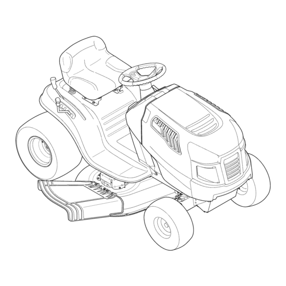
LAWN TRACTOR
7 Speed,
Shift-on=the=Go
42" Deck
Model No. 247.288820
• Espanol,
P. 61
This product
has a low emission
engine
which operates
differently
from
previously
built engines.
Before you start the engine,
read and
understand
this Operator's
Manual.
Before using this equipment,
read this manual and follow
all safety
rules and operating
instructions.
For answers
to your questions
about
this product,
Call:
1-800=659=5917
Craftsman Tractor Help Line
7 am = 7 pm CT, Mort. =Sun.
Sears Brands
Management
Corporation,
Hoffman
Estates,
IL 60179 U.S.A.
Visit our website:
www.craftsman.com
Form No.769-08538
(November 26,2012)
Advertisement
Table of Contents

Related Manuals for Craftsman 247.288820


Summary of Contents for Craftsman 247.288820
- Page 1 I:RnFrSMRN° LAWN TRACTOR 7 Speed, Shift-on=the=Go 42" Deck Model No. 247.288820 • Espanol, P. 61 This product has a low emission engine which operates differently from previously built engines. Before you start the engine, read and understand this Operator's Manual.
- Page 2 Withproofofpurchase, a newcastironfrontaxlewillbe supplied freeofcharge. WARRANTYSERVICE Forwarrantycoveragedetailsto obtainfree repairor replacement, c all 1-800-659-5917 or visit the website: www.craftsman.com In all casesabove,if part repairor replacement i s impossible,the ridingequipmentwill be replacedfree of chargewith the sameor an equivalent model.
- Page 3 This machinewas builtto be operatedaccordingto the safeopera- This symbolpointsout importantsafetyinstructionswhich,if not tion practicesin this manual.As with anytype of powerequipment, followed,couldendangerthepersonalsafetyand/orpropertyof carelessnessor error on the partof the operatorcan resultin serious yourselfand others. Readand followall instructionsin this manual injury.This machineis capableof amputatingfingers,hands,toes beforeattemptingto operatethis machine.Failureto complywith and feet and throwingdebris.Failureto observethe followingsafety these instructionsmay resultin personalinjury.Whenyou seethis...
- Page 4 SLOPE OPERATION • Slowdownbeforeturning.Operatethe machinesmoothly.Avoid erraticoperationand excessivespeed. Slopesare a majorfactorrelatedto loss of controland tip-over Disengageblade(s),set parkingbrake,stopengine and wait until accidentswhichcan result in severeinjuryor death.All slopes require the blade(s)come to a completestop beforeremoving grass extra caution.If youcannot back up the slopeor if youfeel uneasyon catcher,emptyinggrass,uncloggingchute,removinganygrass or it, do not mowit.
- Page 5 CHILDREN SERVICE Tragicaccidentscanoccur ifthe operatoris notalert to the presence SafeHandlingof Gasoline of children.Childrenare often attractedto the machineand the mowing Toavoidpersonalinjury or propertydamageuse extremecarein activity.They do notunderstandthe dangers.Neverassumethat handlinggasoline.Gasolineisextremelyflammableand the vaporsare childrenwill remainwhereyou last sawthem. explosive.Seriouspersonalinjury canoccur whengasolineis spilled • Keepchildrenout of the mowingareaand inwatchfulcare of a on yourselfor your clotheswhich can ignite.
- Page 6 General Service • Donot changethe enginegovernorsettingsor over-speed the • Never run anengine indoors orina poorly ventilated area. Engine engine.The governorcontrolsthe maximumsafe operatingspeed exhaust contains carbon monoxide, anodorless, and deadly gas. of the engine. • Before cleaning, repairing, orinspecting, make c ertain the Maintainor replacesafetyand instructionlabels,as necessary.
- Page 7 SAFETY SYMBOLS This pagedepictsand describessafety symbolsthat may appearon this product. Read,understand,and follow all instructions on the machine beforeattemptingto assembleand operate. READ THE OPERATOR'S MANUAL(S) Read, understand, and follow all instructions in the manual(s) before attempting to assemble and operate DANGER-- ROTATING BLADES Never carry passengers.
- Page 8 15° Slope 15° Slope (OK) (TOO STEEP) '_. _ Figure 1 Figure 2 15° dashed line USETHISSLOPE GAUGE TODETERMINE IF A SLOPE IS TOOSTEEPFORSAFEOPERATION! To checkthe slope, proceedas follows: Removethis pageand fold along the dashedline. Locatea verticalobject on or behindthe slope (e.g. a pole, building,fence, tree, etc.) 3.
- Page 9 IM PORTANT: Yourtractorisshippedwith motoroil inthe engine.However, Shipping BraceRemoval youMUST check the oil levelbefore operating. R eferto the Service & Maintenance sectionforinstructions on checking the oil level. Makesurethe riding mower'sengine isoff, removethe ignition key,and Attaching the Battery Cables set the parkingbrake beforeremoving the shipping brace.Referto the Operaton sect on for nstruct ons on how to setthe park ng brake.
- Page 10 Slidethe seatrearwardin the seatpivotbracket(c),liningup the center rearslotinthe pivot bracket w ith the remainingholeinthe seat's base.See Figure S. Note: Becertainthe two seattabsengauge the pivot bracket a sshownin the bottominsetof Figure 5. Figure3 Place the steeringwheel capoverthe centerof the steeringwheeland pushdownwarduntil it "clicks"into place. Attaching The Seat If the seatforyourtractorwasnot attached at the factory,referto the following Figure 5...
- Page 11 NOTE: A nyreference i nthis manual t o the RIGHT o r LEFT s ideof the tractorisobserved fromoperator's seatpositionfacingforward towards the front of tractor. Meets ANSI S afety Standards Craftsman T ractors conform to the safetystandard ofthe American National S tandards I nstitute(ANSI).
- Page 12 Shift Lever SpeedControlLever Theshift leverislocated on the left side Thespeed control l ever,Moated onthe left sideofthe tractor's dashconsole, a llowsyouto regulate thegroundspeed ofthe lawn of the fenderandhasthreepositions, tractor.Touse,depress t he dutch-brakepedal a ndmovethe lever FORWARD, NEUTRAL andREVERSE. out ofthe parkingbrakenotchandforwardto increase the tractor's clutch-brake pedalmustbedepressed andthetractormustnot bein motion groundspeed.
- Page 13 Gasand Oil Fill-up IMPORTANT: Yourtractorisshippedwith motoroil in the engine.However, you MUST check the oii levelbefore operating. B ecareful n ot tooverfill. Forinstructionsonhowto check the engineoil,referto Checking TheEngine Oilin the Service a ndMaintenance s ectionof thismanual. Gasoline Thegasoline tank islocatedunderthe hood.Donotoverfill. Useextreme carewhen handling gasoline.Gasolineisextremely flammable andthe vaporsareexplosive.Neverfuel machineindoorsor while the engine ishotor running.
- Page 14 Theenginewill automatically s hut off if the PTO (Blade Engage) l everis Setting the CuttingHeight movedintothe engaged (ON)positionwith the shift leverinReverse. Select t he heightpositionof the cuttingdeckbyplacingthe decklift leverin Ignition Switch anyof thesixdifferentcutting heightnotches onthe rightsideof the fender. Theignitionswitchisactivated to startthe engine.Insertkeyintothe ignition switchandturn clockwise to the START p osition.Release the keyinto the ON Keephandsand feet away from the discharge opening of the cutting positiononceenginehasfired.SeeFigure 8.
- Page 15 Engage the parkingbrake. Stopping the Engine Shutengineoff andremove the key.Doing sowill minimizethe possibility of havingyourlawn"browned"byhot exhaust f romyourtractor'srunning If you strike a foreign object,stop the engine,disconnectthe sparkplug engine. wire(s) andground againstthe engine.Thoroughlyinspectthe machinefor Ifunit stallswith speed control i n highspeed, o r if unit will not operate with speed anydamage.
- Page 16 Mulching Headlights Amulchkit isavailableasanattachment. M ulchingisa process o f redrculating ThelampsareON whenever the tractor'sengineisrunning. grassclippings repeatedly beneath the cuttingdeck.Theultra-fineclippings are Thelampsturn OFF whenthe ignition keyismoved to the STOP p osition. thenforcedbackintothe lawnwherethey actasanaturalfertilizer. Amulchkit canbepurchased. See the Replacement Parts &Attachments sectionof thismanual f ormoreinformation.
- Page 17 MAINTENANCE SCHEDULE Beforeperforminganytype ofmaintenance/service, disengage all controls Follow the maintenance s chedule givenbelow.Thischartdescribes s ervice andstopthe engine.Waituntil all movingpartshavecometo acomplete guidelines only.Use the Service Logcolumn to keeptrackofcompleted stop.Disconnect sparkplugwire andgroundit againstthe engineto prevent maintenance t asks.Tolocate the nearest Parts & RepairServiceCenter or to unintendedstarting.Always wearsafetyglasses d uringoperationor whUe schedule service,simply contact 1-800-659-5917.
- Page 18 Changingthe Engine Oil and Filter Engine Maintenance Checkingthe EngineOil Onlyusehighqualitydetergentoil ratedwith APIservice classification S F, S G, If the engine hasbeenrecently run, the engine,muffler andsurrounding SH, o r SJ. S elect t he oil'sSAE viscosity gradeaccording to the expected operating metal surfaceswill be hot and cancause burns to the skin.
- Page 19 Beforereplacing the fuel filter,drainthe fuel tank.Otherwise, fuel canleak out andcause afire orexplosion. ToDrainthe fuel: Locate the fuelfilter,seeFigure 12,whichisrouted on theleft sideofthe engine between the fueltankandthecarburetor, andmaybeattached to the engine withatie strap. C utthetiestrap,if present, t henpinchthe tabsonthe in-lineclamponthefuel filter withapairof pliers, s lidethe clampupthe fuel line.Pull t he fuellinefreefrom thefilter andplace the open endof the lineinto anapproved container t odrainthe fuel.
- Page 20 Air Cleaner Remove t he foampre-fiIterfrom aroundthe paperairfilter. SeeFigure 15.Replace p aperelement w hen dirty or damaged. C lean foamelement o r Paper f ilters cannotbecleaned andshouldbe replaced every100operatinghours; replace whendamaged. moreoftenif usedin extremely dustyconditions. Neverusegasolineor low flash point solventsfor cleaningthe air filter element.Afire or explosioncould result.
- Page 21 Attachthe airfilter cover, m aking sureto alignplasticrib features onthe Measure the plug gapwith afeelergauge. C orrect a snecessary b ybending shroudto the plastic features on the airfilter cover. S eeFigure 17. T urn sideelectrode. S eeFigure 19.Thegapshouldbesetto 0.024-0.031 i n. thumbscrews clockwise untilsnug.Check f or anymisalignment.
- Page 22 Lubrication IMPORTANT: Theuseofa pressure w asher to cleanyourtractorisNOT recommended. It maycause damage to electrical c omponents, spindles, p ulleys, bearings orthe engine. Beforelubricating, repairing, o r inspecting, alwaysdisengagePTO (Blade Adjustments Engage Lever),moveshift leverintoneutral position, set parkingbrake,stop eng ne andremovekeyto prevent un ntendedstart rig. Neverattempt to makeanyadjustments while the engine isrunning, e xcept where specifiedin the operator'smanual.
- Page 23 Sideto Side Cutting Deck Removal To removethe cutting deck,proceed asfollows: If the cuttingdeck appears to bemowingunevenly, asideto sideadjustment c anbe performed. A djustif necessary a sfollows: Place the PTO (BladeEngage)lever i n the disengaged (OFF) p ositionand With thetractorparkedona firm, levelsurface, p lace the decklift leverin engage the parkingbrake.
- Page 24 PTOCable Figure23 Figure25 Remove t he bow-tiecotterpin securing the deckstabilizerrodto the deck. Tires Slide the decklift rodfromthe mountingbracket o n the deckasshownin Figure 24. Neverexceedthe maximuminflationpressureshown on the sidewall of tire. ,,_ _ /,_ _ , ......The recommended operating tire pressure is: Approximately 10psiforthe reartires Approximately 14psiforthe front tires IMPORTANT:...
- Page 25 Connect t he second cable(negative -) to the otherpostofthe jumper Remove t he deckfrombeneaththetractor,(referto CuttingDeckRemoval battery. earlierinthissection) t hengentlyflip the deck overto expose its underside. Connect t he otherendof the negative cableto the engineblockof the Place ablockof woodbetweenthe centerdeckhousingbaffleandthe tractor,awayfrom the battery. A ttachtoan unpaintedpartto assure agood cutting bladeto actasa stabilizer.
- Page 26 NOTE: Whenreplacing the blade,besureto installthe bladewith thesideof the Thenroutethe beltaroundthe twodeckidlerpulleysasshownin Figure 28. blademarked "Bottom" (orwith a partnumberstamped in it) facingthe ground Retighten the beltkeeperrodloosened earlier. whenthe moweris inthe operatingposition. Remount the beltguardsremoved earlier. Re-install t hedeck,makingsurethe belt remainsroutedaround the pulleys Use a torque wrenchto tighten the bladespindle he×flange nut to between asinstructed.
- Page 27 Neverstore lawn tractor with fuel in tank indoorsor inpoorly ventilated areaswhere fuel fumes may reachan openflame, spark,or pilot light ason afurnace,water heater,clothesdryer,or gasappliance. PreparingTheEngine DrainingThe Fuel IMPORTANT: Fuel l eft inthe fuel tankduringwarmweatherdeteriorates a nd Locate the fuel filter,whichis located onthe left sideofthe engine,andmay will cause serious startingproblems.
- Page 28 Enginefails to start PTO/BladeEngageleverengaged. Placeleverin disengaged(OFF) position. Parkingbrakenotengaged. Engageparkingbrake. Sparkplugwire(s) disconnected. Connectwire(s)to sparkplug(s). Throttle/Chokecontrollevernot in correct PlaceThrottle/Chokeleverintothe FASTposition. startingposition. Chokenotactivated MovetheThrottle/Chokeleverintothe Choke position. Fueltank empty,or stalefuel. Filltank with clean,fresh (less than30 daysold) gas. BIockedfuel line. Replacethe fuel line and replacefuel filter. Faultyspark plug(s).
- Page 29 FuelCap 951-12179A 777D17045 Partsavailableat mostSeatsRetailStores a ndService Centers orcall1-800-36G-PART(7279) if youwant t hepart sentdirectly t oyogrholue. X46377 Specific tractor attachmentsfor your Craftsman tractor a vailableat Sears Stores and ServiceCeaters. Seebelow forotheruniversal attachments alsoavailable. Description Stock No. Mulch Kit 33748 Bagger...
- Page 30 Craftsman IViodel 247.288820 55 56...
- Page 31 Craftsman Model 247.288820 Part No, Description Part No, Description Ref, Ref, 925-1649 Bulb Socket 741-0587 Steering Column Bearing 712-04063 683-04619A-0691 Nut, Hex Flange Lock, 5/16-18 Hood Assembly 783-06785A Screw, 5/16-18 x .750 Steering Support Bracket 710-04484 710-0599 783-06811-0637 Dash Hex Washer Screw, 1/4-20 x .500...
- Page 32 Craftsman Model 247.288820...
- Page 33 Craftsman Model 247.288820 Part No. Description Part No. Description Ref. I Ref. I 756-04196A 683-04155A-0637 EngagementPulley Shaft, Lift 747-04857 712-04065 Belt KeeperRodAssembly Nut, HexFlangeInsertLock, 3/8-16 710-04484 714-04040 Screw,Hd.Tapp,5/16-18x .75 Bow-TiePin,91, RH 683-04195-0637 716-0106A SupportBracketAssembly E-ring,.625Shaft 683-04649A-0637 720-0311 Rider FrameAssembly Grip,Handle...
- Page 34 Craftsman IViodel 247.288820 ....33 _ /_ ......
- Page 35 Craftsman Model 247.288820 Part No. Description Part No, Description Ref, Ref, 617-04094 683-0128B-0637 GearAssembly, S teering PivotBarAxle Assembly 710-0643 Screw,5/16-18,1.00,Gr5,Lock 710-04484 Screw,5/16-18,0.750 712-04065 710-1309 Screw,Mach,5/16-18,0.750 Nut, FlangeLock, 3/8-16,GrF 710-0514 714-0162 Pin, Cotter,5/32, 1.25 HexHead Screw,3/8-16x 1.00 914-0474 710-3180 Pin, Cotter,1/8 x 0.75 Screw,5/16-18,1.75,Gr5...
- Page 36 Craftsman IViodel 247.288820...
- Page 37 Craftsman Model 247.288820 Part No. Description Ref. 710-0227 Screw,8-18 x .500 710-04484 Screw,5/16-18x .750 712-04063 FlangeLockNut, 5/16-18 720-04061 Knob,3/8-16x .875 925-1303 OuterSeat Spring 725-1439 InnerSeatSpring 726-0278 InsulatorBossPlate 726-0279 InsulatorPlate 732-1184 ExtensionSpring 936-0108 FiatWasher,.510x .750x .033 736-0242 FlatWasher,.340x .872x .060 938-0296 ShoulderScrew,5/16-18x .437x .268...
- Page 38 Craftsman IViodel 247.288820 ..11J_ .......
- Page 39 Craftsman Model 247.288820 Fief. I Part No. Description 683-04549 Muffler Shield Assembly with Weld 710-0227 Screw, 8-18 x .500 710-04683A Screw, 3/8-16 x 1.0 710-0599 Screw, 1/4-20 x .500 710-0642 Screw, 1/4-20 x .750 712-04064 Flangelock Nut, 1/4-20 712-3086 Flange Nut, M8-1.25...
- Page 40 Craftsman Model 247.288820 " > 28...
- Page 41 Craftsman Model 247.288820 Part No. Description Part No. Description Ref, I Ref. I 747-05188 BrakeRod 918-04566 TransmissionDriveAssembly 647-04034C-0637 747-05244 Shift Rod PedalAssembly 738-04237A 647-04266 ShoulderScrew,#10-32x .500 Shaft LeverAssembly 750-0566A 710-0227 Screw,8-18:0.500 Spacer,.260 x .375x 1.030LG 750-0802 710-04484 Screw,5/16-18 x .750 Spacer,.640 ID x .76 OD x 2.63...
- Page 42 Craftsman Model 247.288820 10\®\ @_/18 _\15...
- Page 43 Craftsman Model 247.288820 Part No. Description Part No. Description Ref, Ref, 918-04822A 936-0119 Washer, Lock, 5/16, Regular Duty Spindle Ass'y, Pulley, 6.3 Dia 683-0254B 941-0919A Bracket Ass'y, Deck, Hanger LH Bearing, Ball, .787id x 1.85 Odx.551 936-0344 Washer, Flat, .385 X 1.0 X .030...
- Page 44 Craftsman Engine Model 4P90HU For Model 247.288820 121--_ _124 127__ 951-14458 Air Filter CoverAssembly 951-14466 Air Filter Lock Nut 951-12255 Air Filter Cover 951-12256 SpongeFilter 951-12260 Air FilterAssembly 712-04212 Nut M6 951-12328 RubberCap 951-12257 Manifold 951-12258 ManifoldGasket...
- Page 45 Craftsman Engine Model 4P90HU For Model 247.288820 951-12205 DebrisShield 712-04290 750-05320 EngineShroudSpacer 951-14454 Starter/ ShroudStud M6x99 951-11622 FlexibleClamp 710-05305 Hook Bolt 951-14455 Air Shield 710-05303 Self-Tapping Bolt5.5x25...
- Page 46 Craftsman Engine Model 4P90HU For Model 247.288820 s1-_ 191- Gasket Kit- External 192- Gasket Kit- Complete _---53 193- Complete Engine 1_3- U _181...
- Page 47 Craftsman Engine IViodel 4P90HU For IViodel 247.288820 951-11499 750-05530 ComponentBracketSpacer UpperCrankshaftSeal 710-04916 Bolt M6x14 951-12235 BreatherHoseAssembly 951-14456 BreatherCoverPlate 951-12236 BreatherHoseClamp 951o14462 951-12226 BreatherGasket ShortBlockAssembly 951-12685 UmbrellaValve (Incl.37,47-53,55-58,73-77,84, 951-12227 MeshScreen 86-89,91-93,98-104,112,113, 951-12686 UmbrellaValveSeat 115-119,137,138,144,158,170, 951-12228 ChokeLinkage 171,173-176,181 -184) 951-12229 GovernorArm Shaft...
- Page 48 Craftsman Engine Model 4P90HUFor Model 247.288820 191- Gasket Kit- External 192- Gasket Kit- Complete 193- Complete Engine 152_ _153 i_5 15oio2 1401 _--- _140...
- Page 49 Craftsman Engine IViodel 4P90HU For IViodel 247.288820 951-12202 710-05315 BoltM5xlO CylinderHead Kit 951-12265 Cowl (Incl.114,154,161,162,170) 951-14463 710-05316 ValveCoverBolt CylinderHeadAssembly 951-12266 ValveCover (Incl.137-139,144,146-159, 951-14460 Air ValveCore 951-12267 ValveCoverRing 951-12775 951-11981 StrainerClip RockerArmAssembly 951-12776 SecondAir ValveFilterElement 751-11124 Jam Nut 951-12777 The Air ValveBonnet...
- Page 50 Craftsman Engine Model 4P90HU For Model 247.288820 --75 82 _81...
- Page 51 Craftsman Engine IViodel 4P90HU For IViodel 247.288820 951-11622 951-12248 Oil PumpAssembly FlexibleClamp 951-12238 951-12247 O-Ring10x2.65 CrankshaftAssembly 951-11969 951-12249 Filter MainBearing 951-12250 951-10307 WoodruffKey FilterSpring 951-12239 951-12251 O-Ring35.5x2.65 DipstickAssembly 951-12241 951-12252 FilterCover UpperO-Ring 951-11956 951-12363 LowerO-Ring GovernorGear/ShaftAssembly 710-05313 BoltM8x15 951-12240 Oil FillTubeAssembly...
- Page 52 Craftsman Engine Model 4P9OHU For Model 247.288820 --133 131-- 194- Carburetor Kit-Major...
- Page 53 Craftsman Engine Model 4P90HU For Model 247.288820 951-12258 ManifoldGasket Nylon/Plastic O-Ring 951-12771A FiberO-Ring Carburetor Assembly 951-11731 FuelHoseClamp IdleSpeedAdjustingScrew IdleMixtureScrew 951-11336 FuelLine Kit 723-04071 Carburetor Body PlasticSupportClamp 951-12261 Carburetor Gasket FuelInlet FloatPin 951-12262 CarburetorInsulator EmulsionTube 951-12263 CarburetorInsulatorGasket 951-12264 CarbStud NeedleValve 951-14179...
- Page 54 Craftsman Engine IViodel 4P90HU For IViodel 247.288820 710-04931 BoltM6x28 951-12220 IgnitionCoil Assembly 712-04220 FlywheelNut M16x1.5 951-12221 Plate 951-12222A CoolingFan 951-12223 Flywheel 951-12224 Coil Assy.Charge 710-04940 BoltM6xlO 951-12279 Cowl...
- Page 55 Craftsman Engine Model 4P90HU For Model 247.288820 11--o o--ll =-12 11 _12 _--17 710-05306 BoltM8x40 951-12528 StarterHousingAssembly 951-12207 951-12217 Screw StarterAssembly 710-05307 Screw M5x25 736-04554 LockWasher 736-04554 LockWasher5 951-12529 Brush Assembly 736-04556 PlainWasher6 951-12219 ElectricalStarterBack Cover Electrical S tarter FrontCover...
- Page 56 Look For Relevant Emissions Durability Period and Air index information On Your Engine Emissions Label Engines that are certified to meet the California Air Resources Board (CARB) Tier 2 Emission Standards must display information regarding the Emissions Durability Period and the Air Index. Sears Brands Management Corporation makes this information available to the consumer on our emission...
- Page 57 (Thispage applicablein the U.S.A.and Canadaonly.) Sears Brands Management Corporation (Sears), the California Air Resources Board (CARD) and the United States Environmental Protection Agency (U.S. EPA) Emission Control System Warranty Statement (Owner's Defect Warranty Rights and Obligations) EMISSIONCONTROL WARRANTY COVERAGEISAPPLICABLE TO CERTI- YEAR 1997AND LATERENGINES WHICHARE PURCHASED AND USED FIEDENGINESPURCHASEDIN CALIFORNIAIN 1995ANDTHEREAF- ELSEWHERE IN THE UNITEDSTATES (ANDAFTERJANUARY1,2001 IN...
- Page 58 FEDERAL and/or CALIFORNIA EMISSION CONTROL W ARRANTY S TATEMENT YOUR WARRANTY RIGHTS ANDOBLIGATIONS MTD Consumer Group Inc, the United States Environmental Protection Agency (EPA), and, for those products certified for sale in the state of California, the California Air Resources Board (CARB) are pleased to explain the emission (evaporative and/or exhaust) control system (ECS)
- Page 59 10. Add-on o rmodified parts t hatare not e xempted bythe AirResources Board m ay not b eused. The use ofany non-exempted add-on o r modified parts b ytheultimate purchaser willbegrounds fordisallowing awarranty claims. MTD Consumer Group I nc willnotbeliable t o warrant failures ofwarranted parts c aused bytheuse ofanon-exempted add-on o rmodified part.
- Page 60 Congratulations on making a smart purchase. Your new Craftsman® product is designed manufactured for years of dependable operation. But like all products, it may require repair from time to time. That's when having a Repair Protection Agreement can save you money and aggravation.
- Page 61 Fuera de temporada de almacenamiento .. Page 87 Servicio de nOmeros .... atrasados Page CRAFTSMAN GARANTJA COMPLETA DURANTE dosa_osdesdelafechade cornpra, t odaslaspartesde nofungibles de esteequipo de equitaci6n estangarantizadas contracualquier defectode material o rnanode obra.Unaparteno fungibles defectuosa recibir_ a dornicilio reparaci6n o la sustituci6n si la reparaci6n noest_ disponible.
- Page 62 Lapresencia deeste sirnbolo indica que se trata deinstrucciones Esta rn_.quina rueconstruidapara seroperadade acuerdocon irnportantes deseguridad que sedeben r espetar para evitar las reglasde seguridadcontenidasen este manual.AI igualque poner enpeligro suseguridad personal y/omaterial yladeotras concualquiertipo de equipo rnotorizado, u n descuidoo error por personas.
- Page 63 • Nuncadeje la rn_.quina e n funcionarniento sinvigilancia. A pague Vayaa bajavelocidad.ElijaunavelocidadIosuficienternente b aja, siernprelascuchillas, c oloqueel frenode rnano,detengael motory de rnodoque no tengaque detenerse o hacercarnbios rnientras retirela Ilaveantesde bajarsedel vehiculo. est,. sobrela pendiente. L osneurn_.ticos podrianperdertracci6n sobrelaspendientes aQn cuandolos frenosfuncionaran apro- •...
- Page 64 • Paraevitaraccidentes al operaren rnarcha atr_.s, s iernpre desengan- Apaguetodos loscigarrillos,cigarros,pipasy otrasfuentesde chelascuchillas antesde colocarrnarcha atr_.s. Si est,.instalado, cornbusti6n. el "ModoPrecauci6n Marcha Atr_.s" ( hojasde operarla rn_.quina, • Nuncacarguecombustibleen la rn_.quina en un espaciocerrado. rnientras quelos paseos a la inversa) n o debeutilizarse cuandohay •...
- Page 65 NO MODIFIQUE EL MOTOR • Reviselos pernosde rnontajede la(s)cuchilla(s)y del motor a intervalosfrecuentes para verificarque est_n bienapretados. Paraevitarlesionesgraveso la rnuerte,no rnodifiqueel motorbajo Adern_.s, inspeccionevisualrnente la(s) cuchilla(s)en buscade ningunacircunstancia. S i carnbiala configuracidn del reguladordel da_os(por ejernplo,desgasteexcesivo,abolladuras,rajaduras, motorel motor puededescontrolarse y operara velocidadesinsegu- etc.).
- Page 66 S[IVIBOLOS DE SEGURIDAD Esta p&ginarepresenta y describela seguridadlos simbolosque puedenpareceren este producto.Lea,comprenda,y sigatodas instrucciones en la m_quinaantesprocurarpara reuniry operar. LEA EL MANUAL(S) DEL OPERADOR leido, entienda, y siga todas las instrucciones en el manual(s) antes de procurar montar y funcionar PELIGRO-- DE EL CORTE DE PIE Nunca transporte pasajeros.
- Page 67 15 ° Pendiente 15 ° Pendiente (ACEPTAR) (DElVlASlADO ESCARPADO) FiguraI Figura2 ¢0 15°/fn US0 DE ESTEPENDIENTEDE CALIBREPARADETERMINAR SI UNA PENDIENTE ES DEMASIADOESCARPADO PARA UNA OPERACIONSEGURA! Para comprobar la pendiente, haga Io siguiente: Borrar esta p@ina y doble a Io largo de la linea discontinua. Localizar un objeto vertical sobre o detr_.sde la pendiente (un poste, un edificio, una valla, un _.rbol,etc.) Alinee cada lado de pendiente de calibre con el objeto vertical (consultar Figura 1 and Figura 2 ).
- Page 68 IMPORTANTE: Su tractorseentregaconaceite de motoren el NOTA: Si la bateriase poneen serviciodespu_sde la fechaindicada motor.Sin embargo,debe comprobarel nivelde aceiteantes de en la partesuperiorde la bateria,carguela bateriacomo se indicaen operar.Consultela secci6nde Servicioy Mantenimiento para obtener el Servicioy Uantenimiento de la secci6nde este manualantesde instrucciones sobrela comprobaci6ndel nivelde aceite.
- Page 69 QUE UNE EL VOLANTE Si el volantede su tractorno Ileg6adjunta,el hardwarede la colocaci6nse ha embaladoen el volante,por debajode la tapadel volante.Concuidadola tapa de la palancadel volantey quitarel hardware. Conlas ruedasdel tractor,apuntandodirectamente haciadelante, colocarel volantesobreel eje de direcci6n. Coloquela arandela(con la parteahuecadahaciaabajo) sobreel volantey seguracon el tornillohexagonal.
- Page 70 © Figure34 Palanca d el frenodeestadonam[ento Acelerador y palanca de control d e Choke Interruptor d eencend[do Levante [apa[anca de[acubierta Toma de fuerzadepalanca (BladeEngage) Portavasos DeVeloddad Pedal d efreno NOTA: Cualqu[er referendahecha enestemanual a l ladoDERECHO oIZQU IERDO deltractordebeentenderse tal comoseobserva desde la posidbndeloperador. Curnpiecon losest_ndaresde seguridad de ANSi Las m_iqu[nas qu[tan[eve deCraftsman cumplen conlosest_indares desegur[dad del[nstituto estadounidense deest_indares nadonales (ANSI).
- Page 71 DeVeloddad Para apagar elmotor g irea laizquierda l aIlave deencendido hasta laposid6n d e STOP. Lapalanca de control d eveloddad, u Ncadoen elladoizquierdo IMPORTANTE: Antesde operarel tractor,se refierentanto al deltablerodeltractordelaconsola, l epermiteregularlaveloddad "Sistemade bloqueode seguridad"y "Arranquedel motor"m&s bajadeltractordelc_sped. P ara usarlo, p resione el pedal d e adelanteen esta secci6nde este manualparainstrucciones detalladas freno-embrague y moverlapalanca delamuesca de frenode sobrela Ilavede encendidodel m6dulo.
- Page 72 Gasolina Tengamuchocuidadoal trabajarcongasolina.Lagasolinaessumamente inflamable y susvaporespuedencausare×plosiones. N uncacargue combustibleen la m_quinaen un espaciocerradoocuandoel motor est_ caliente oen marcha.Apaguecigarrillos, cigarros,pipasy otrasfuentesde combusti6n. NOTA : Compre gasolina en pequeffas c antidades. N ousegasolina quehaya quedado delatemporada anterior,paraminimizarlaformaci6n de dep6sitos d e gomaenel sistema decombustible. Este motorest_habilitadoparafuncionar c ongasolina sinplomo.Para obtenerelmejorresultado, lleneeldep6sito de combustible unicamente con gasolina sinplomolimpiay fresca, e n unsurtidorqueindiqueunoctanaje...
- Page 73 Paraactivar el freno de estadonamiento: Sistemade bloqueode seguridad Completamente e lpedaldefrenoy mantengahacia abajoconelpie. Elsistema de bloqueodeseguridad est_diseffado paralaoperad6n seguradel tractor.Siestesistemanunca dejadefuncionarcorrectamente, no opereeltractor, Moverlapalanca delfrenode estacionamiento h astael rondoyen elfreno contacte inmediatamente c onsuSears Parts & Repair S ervice Center. de estadonamiento ( ON) l a poski6n.
- Page 74 Parodel motor INIPORTANTE: AIparareltractor,porcualquiermotivo,mientras queenuna superficie de hierba, s iempre: Coloque l apalanca decambios en puntomuerto, Sisegolpeaun objeto e×traffo,detengael motor,desconecte el cablede la Apliqueelfrenodeestacionamiento, bujia (s)y tierra contrael motor. Inspeccionar c uidadosamente el equipo de losdaffos.Reparaci6n de losdaffosantesde reiniciar y defuncionamiento. Apague el motory quitar laIlave.SiIohace, r educir,_ a lm[nimolaposibilidad dequesuc_sped sedore'"'porelescape calientedel motordesutractor.
- Page 75 Involucrar a losBlades Fal'os PartJcipacJ6n de [atomadefuerza(Blade Engage) lastransferencias deenergia ala Las l&mparas e st&nON cuandoelmotordeltractorseest&ejecutando. plataforma decorteodeotrotipo(disponible p orseparado) losarchivos adjuntos. P ara Las luces seapagacuando lallavedecontactosemueve a laposici6n STOP. partidpardelashojas, h agaIoslgulente: Moverlapalanca de control d elacelerador a lar@ida(conejo) l aposicJ6n. Sujete latomadefuerza(BladeEngage) y girar lapalanca de todoel camlno asegulralosnovJos ( ON) l aposid6n.
- Page 76 LISTA DEMANTENIMIENTO Antesde realizarcualquiertipo del mantenimiento/servicio,sueltetodoslos Sigalalistademantenimiento dadaabajo.Esta cartadescribe pautas deservicio mandosy pare el motor. Espere h astaquetodas laspartesdemovimiento s61o. U se lacolumna de Tronco deServicio paraguardarlapistadetareasde hayan venido a unaparadacompleta. D esconecte el aiambrede bujia y mantenimiento completadas. b_selocontrael motor para prevenirel comienzoinvoluntario. SiempreIleve Local[zar e l m_scercano Chamuscael Centro de Servicioo programarel puestoscristaiesinastillables d urante la operaci6no reaiizandocualquier servicio, simplemente ponerse encontactoChamusca en 1-800-659-5917.
- Page 77 Mantenimiento del motor Cambiode aceite motor y filtro Comprobar el aceite del motor $61o elusodeaceitede altadetergente seevalu6lacalidadconlaclasificaci6n deservicio API,SF, S G, S H,o SJ. S eleccione e laceitedegradodeviscosidad SAE de acuerdo condelatemperatura defuncionamiento. Siga latabladeabajo.Aunque variosdelosaceites deviscosidad (5W20, I OW30, etc)mejorarlapartidaenclima frio,quesetraducir_i enelconsumo depetr61eo aumenta cuandoutilizadopor Neta: El f iltro deaceitesedebecambiarencadaintervalodecambio de aceite.
- Page 78 Lleneparcialmente elfiltro deaceiteaproximadamente 3 /4delcamino Cualquier fugadegranvolumendecombustible desde eldep6sito de desconectar lalineadecombustible delfiltro en lalineade combustible completoconaceitelimpioy fresco. A ntesde instalar el nuevo filtro de cercadelmotor. aceite, l ubriqueligeramente laJuntadelfiltro de aceite conpartedelaceite Quitelalineadecombustible de laLN-lado delalinea(ladohacia eltanque simplemente eldedoen elaceitedeinmersi6n y ejecut_ndolo alrededor d e decombustible) d elfiltro decombustible.
- Page 79 Nouseairecomprimido o disolventes p aralimpiarelcartucho delfiltro deaire. IMPORTANTE: Nunca arranque el motorsinel filtro de aire.Resultar_ elr_pido desgaste delmotor. Air Filter, Desatornille lostornillosy retirelacubiertadelfiltro deaire.Yeala Figure 41. Thumb Screw Air Filter Figure43 Tocleanfoamelement, w ashina mildliquiddetergentandwater.Squeeze or pressthe foamelementto rinseout dirt andwater.Donot twist;this coulddamage or tearthe foamelement.
- Page 80 Electrode Air Filter Cover Plastic Feature Figure47 Compruebe q uelaarandela delabujiaest_en buenas condiciones y enrosque labujiaamanoparaevitarquelarosca. Despu(_s dehaberse asentada labujia,apfieteconunaIlave de bujiapara comprimirlaarandela. Nota:AIinstalar unabujianueva, a pfiete1/2vueltadespu_s q uela bujia Figure 45 seasientaparacompfimirlaarandela. C uando v uelvaa instalar unabujia usada, a pfiete1/8-1/4vueltadespu(_s de losasientos dela bujiapara Servicio de la bujia comprimirlaarandela.
- Page 81 Lubricad6n Limpieza de lasm,iquinas y la cubierta Cualquier combustible oaceitederramado en lam_iquina d ebeserborradode [nmediato. N O permitaquelosdesechos q ueseacumulan alrededor delasaletasde Antesde [ubricantes, reparacidno inspecci6n, siempredesconectartoma de refrigeraddn delmotoroencualquier o tra partedelam_iquina. fuerza,palanca decambiosepongaen posicidnneutral, el freno de mano, IMPORTANTE: El usode una lavadorade presidnpara limpiarsu apagueel motor yquite laIlave paraevitar el arranque nodeseado.
- Page 82 Un ladoa otto Paraubicar el Centrode Serviciom_s cercanoSearso para pro- gramarel servicio,simplemente p6ngase en contactocon Sears Silaplataforma decorteparece serlasiega de formadesigual, u n ladoaladode al 1-800-659-5917. ajustepuedeserreallzado. A justes[esnecesarlo I oslguiente: Plataformade torte de eliminad6n Con eltractorestadonado enunasuperfidefirme y nivelada, c oloque lapalanca de levantarlacubiertaen lasegunda delaprimeracategoria Paraquitar la plataforma de torte, haga Iosiguiente: (segunda posicl6n m_salta)y girar ambas hojasdemodoquesean...
- Page 83 PTOCable Figure51 Figure53 Retireelpasador d e lapajarita, a segurar l avarillade estabilizador de la Neum4ticos plataforma alacubierta.Deslice eltiradorde lacubiertadelsoporte en la cubiertacomosemuestra en laFigure 52. Nosobrepasarnuncala presi6nm_×imade inflado clueaparece en lapared lateral de lallanta. ::,2 La presi6n de los neum_ticos recomendada de fundonamiento es el siguiente: _ZZ%:;...
- Page 84 Conectar p ositivo(+) paraenviarporcablepositivo(+) de labateria Cuchillas de torte descargada d esutractor. Conecte e lotro extremodelcableala(positivo+) despu(_s de labateriade Apagueel motor y quite laIlavede encendidoantesde retirar lacuchilla puente. de torte (s)para afilar o de sustituci6n. Protejasusmanosusandoguantes Conecte e lsegundo cable(negativo-)paraelotropuestode labateriadel lgruesosa sujetar a hoja.
- Page 85 Para afinarcorrectamente l ashojasdecorte,retirelamismacantidadde [M PORTANTE: ElV-dntur6nseencuentra ensutractorest_especialmente metalde ambos extremos delashojasa Iolargode losbordes decorte, diseffado paraconectar y desconectar deformasegura. U nsustituto(no0EM) paraleloalbordede fuga,en un25°- 30 ° de_ngulo.Siempre molercadafilo V-correa puedeserpeligroso al nodesvincularse c ompletamente. Para unam_quina delacuchilla decorteporigual a mantener elequilibriode lahojaadecuada. de buenfuncionamiento, laf_bricadecinturones de usoaprobado.
- Page 86 Cubierta la correa Figure 56...
- Page 87 Nuncaalmacenetractor de c_sped con combustibleen el tanque en un espaciocerradooen ,_reas conpocaventilaci6n, dondelosgases del combustiblepuedanalcanzar elfuego,chispaso unaluz piloto comolaque tienen algunoshornos,calentadoresde agua,secadores de ropa oalgun otro dispositivoagas. Extraiga labujiay viertauna(1)onzadeaceiteparamotorporelorifido Preparad6ndei motor delabujiaenelcilindro.Haga girarel motorvariasveces paradistribuirel IM PORTANTE: El c ombustible quequedaen eltanquecuandohatecalorse aceite.
- Page 88 El motor no arranca Perilla de potencia de arranque (PTO) Coloque la perilla en la posicidn de desconexidn conectada. (OFF). No est.1 colocado el freno de mano. Coloque el freno de mano. Se ha desconectado el cable de las bujias. Conecte el cable alas bujias.
- Page 89 Esta pagina se dej6 intencionalmente en blanco. Utilice esta pagina para tomar notas acerca de su tractor.
- Page 90 Esta pagina se dej6 intencionalmente en blanco. Utilice esta pagina para tomar notas acerca de su tractor.
- Page 91 Busque el periodo de duraci6n de emisiones importantes yla informaci6n de clasificaci6n de aire en la etiqueta de emisiones de su motor Los motores cuyo cumpiimiento con los estAndares de emisi6n Tier 2 de la Comisi6n de Recursos Ambientales de California (CARB) est6 certificado deben exhibir la informaci6n relacionada con el periodo de duraci6n de ias emisiones y la clasificaci6n de aire.
- Page 92 (Esta p _.gina seaplica s 61o enEE.UU. yCanada.). Sears Brands M anagement Corporation, el Consejo de Recursos Ambientales de California (CARB) y la Agencia de Protecci6n Ambiental de los Estados Unidos (EPA) Declaraci6n de garantia del sistema de control de emisiones (derechos y obligaciones de la garanfia de defectos del propi=...
- Page 93 DECLARACION FEDERAL y/oDECALIFORNIA SOBRE GARANTJAS EN EL CONTROL DE EIVIISIONES SUS DERECHOS Y OBLIGACIONES EN CUANTO A LA GARANTJA MTDConsumerGroupInc, laAgencia de Protecci6nMedioambiental d e los EstadosUnidos(EPA),y para aquellosproductoscertificadosparasu ventaen el es- tadode California,el Departamento de los Recursosdel Aire de California(CARB)secomplacenen explicarla garanfiaque cubre al sistemade control (ECS)de emisiones(evaporativasy/o de escape)de su equipoy motor(motor de equipos de exteriores)de encendidopot chispa paratodo terreno,peque_o,de exteriores del a_o2006 y a_osposterioresEn California,losnuevosmotoresde equipos de exterioresdebenestar dise_ados,construidosy equipadospara cumplircon las estrictasnormasantipoluci6ndel Estado(en otrosestados,losequipos del a_o 1997y modelosposterioresdebenser estar dise_ados,construidosy equipados...
- Page 94 8. Durante latotalidad del periodo de garantia del motor yequipo para todo t erreno arriba mencionado, MTD C onsumer Group Inc mantendr_ un suministro de piezas bajo g arantia suficiente para satisfacer lademanda esperada de tales piezas. 9. Cualquier pieza de reemplazo se podr_ usar para e lcumplimiento del m antenimiento olas reparaciones...
- Page 95 Felicitaciones por haber realizado una adquisici6n inteligente. El producto Craftsman® que ha adquirido esta diseSado y fabricado para brindar muchos aSos de funcionamiento confiable. Pero como todos los productos a veces puede requerir de reparaciones. Es en ese momento cuando...
- Page 96 Ilame el nt_mero abajo. 1-800-659-5917 Craftsman Help Line www.craftsman.com ® Registered Trademark / Trademark of KCD IP, LLC in the United States, or Sears Brands, LLC in other countries...