Table of Contents
Advertisement
Available languages
Available languages
perator's
I:RnFrSMRN°
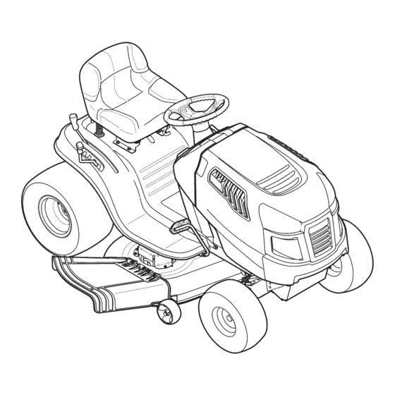
LAWN TRACTOR
19.5 HP, Variation Speed
42" Deck
Model No. 247.288842
• Espanol,
P. 59
This product
has a low emission
engine
which operates
differently
from
previously
built engines.
Before
you start the engine,
read and
understand
this Operator's
Manual.
Before
using this equipment,
read this manual
and follow
all safety
rules and operating
instructions.
For answers
to your questions
about
this product,
Call:
1-800=659=5917
Craftsman Tractor Help Line
7 am = 7 pm CT, Mort. =Sun.
Sears Brands
Management
Corporation,
Hoffman
Estates,
IL 60179 U.S.A.
Visit our website:
www.craftsman.com
Form No.769-06421C
(February 3,2012)
Advertisement
Table of Contents

Related Manuals for Craftsman 247.288842


Summary of Contents for Craftsman 247.288842
- Page 1 I:RnFrSMRN° LAWN TRACTOR 19.5 HP, Variation Speed 42" Deck Model No. 247.288842 • Espanol, P. 59 This product has a low emission engine which operates differently from previously built engines. Before you start the engine, read and understand this Operator's Manual.
- Page 2 W ith proofof purchase,a defectivecastironfront axlewill receivefreein-home replacement. WARRANTYSERVICE Forwarrantycoveragedetailsto obtainfree repairor replacement, c all 1-800-659-5917 or visitthe website: www.craftsman.corn In all casesabove,if part repairor replacement i s impossible, the ridingequipmentwill be replacedfreeof chargewith the sameor an equivalentmodel.
- Page 3 This machinewas builtto be operatedaccordingto the safeopera- This symbolpointsout importantsafetyinstructionswhich,if not tion practicesin this manual.As with anytype of powerequipment, followed,couldendangerthepersonalsafetyand/orpropertyof carelessnessor error on the partof the operatorcan resultin serious yourselfand others. Readand followall instructionsin this manual injury.This machineis capableof amputatingfingers,hands,toes beforeattemptingto operatethis machine.Failureto complywith and feet and throwingdebris.Failureto observethe followingsafety these instructionsmay resultin personalinjury.Whenyou seethis...
- Page 4 SLOPE OPERATION • Slowdownbeforeturning.Operatethe machinesmoothly.Avoid erraticoperationand excessivespeed. Slopesare a majorfactorrelatedto loss of controland tip-over Disengageblade(s),set parkingbrake,stopengine and wait until accidentswhichcan result in severeinjuryor death.All slopes require the blade(s)come to a completestop beforeremoving grass extra caution.If youcannot back up the slopeor if youfeel uneasyon catcher,emptyinggrass,uncloggingchute,removinganygrass or it, do not mowit.
- Page 5 CHILDREN SERVICE Tragicaccidentscanoccur ifthe operatoris notalert to the presence SafeHandlingof Gasoline of children.Childrenare often attractedto the machineand the mowing Toavoidpersonalinjury or propertydamageuse extremecarein activity.They do notunderstandthe dangers.Neverassumethat handlinggasoline.Gasolineisextremelyflammableand the vaporsare childrenwill remainwhereyou last sawthem. explosive.Seriouspersonalinjury canoccur whengasolineis spilled • Keepchildrenout of the mowingareaand inwatchfulcare of a on yourselfor your clotheswhich can ignite.
- Page 6 General Service • Donot changethe enginegovernorsettingsor over-speed the • Never run anengine indoors orina poorly ventilated area. Engine engine.The governorcontrolsthe maximumsafe operatingspeed exhaust contains carbon monoxide, anodorless, and deadly gas. of the engine. • Before cleaning, repairing, orinspecting, make c ertain the Maintainor replacesafetyand instructionlabels,as necessary.
- Page 7 SAFETY SYMBOLS This pagedepictsand describessafety symbolsthat may appearon this product. Read,understand,and follow all instructions on the machine beforeattemptingto assembleand operate. READ THE OPERATOR'S MANUAL(S) Read, understand, and follow all instructions in the manual(s) before attempting to assemble operate DANGER-- ROTATING BLADES Never carry passengers.
- Page 8 15° Slope 15° Slope (OK) (TOO STEEP) '_. _ Figure 1 Figure 2 15° dashed line USETHISSLOPE GAUGE TODETERMINE IF A SLOPE IS TOOSTEEPFORSAFEOPERATION! To checkthe slope, proceedas follows: Removethis pageand fold along the dashedline. Locatea verticalobject on or behindthe slope (e.g. a pole, building,fence, tree, etc.) 3.
-
Page 9: Attaching Steering Wheel
IMPORTANT: Y ourtractoris shippedwith motoroil in theengine. Shipping Brace Removal However, y ou MUSTcheckthe oil levelbeforeoperating.Referto the Service& Maintenancesectionfor instructionson checkingtheoil level. Makesurethe ridingmower'sengineis off, removetheignitionkey, Attaching the Battery Cables and set the parkingbrakebeforeremoving the shippingbrace. Refer Ito the Operationsectionfor instructionson howto set the parking lbrake. -
Page 10: Attaching Seat
Adjusting the Seat Toadjust the positionof the seat,pull up and hold the seat adjustment lever.Slide the seatforwardor rearwardto thedesiredposition;then releasethe adjustment l ever.Makesure seatis lockedintopositionin a seat-stopbeforeoperatingthe tractor.See Figure5. Beforeoperatingthe tractor,makesurethe seat is engagedin a seat-stop.Engagethe parkingbrake.Standbehindthe machineand pull backon seatuntil it clicks intoplace. Figure3 Placethe steeringwheelcap overthe center of the steering wheeland pushdownwarduntilit "clicks"intoplace. - Page 11 Figure6 ParkingBrakeLever PTOLever(Blade Engage) Throttle/ChokeControlLever Cup Holder Shift Lever IgnitionSwitchModule Auto-drivePedal SeatAdjustmentLever DeckLift Lever BrakePedal NOTE: Any referencein this manualto the RIGHTor LEFT sideof the tractoris observedfrom operator'sseat positionfacingforwardtowardsthe frontof tractor. Meets ANS! Safety Standards CraftsmanTractorsconformto the safetystandardof theAmericanNationalStandardsInstitute(ANSI).
- Page 12 PARKING BRAKE LEVER AUTO-DRIVE PEDAL To set the parkingbrake: Fullydepressthe brakepedal.Movethe The drivepedal is locatedon the right sideof the tractor,along the parkingbrakeleverintothe parkingbrakeposition.Releasethe brake runningboard.Depressthe drivepedalforwardand the tractorwill pedalto allowthe parkingbraketo engage. move in the directionthat the shiftleveris engagedin. Tocausethe tractorto travelforward,whileat a completestop,movethe shift lever To releasethe parking brake: Depressthe brakepedaland the park- into the Forwardposition.Graduallystep on the drivepedal and the...
- Page 13 GAS AND OIL FILL-UP IMPORTANT: Yourtractorisshippedwith motoroil in the engine. However, y ou MUSTcheckthe oil levelbeforeoperating.Be careful not tooverfill. For instructions on howto checkthe engineoil, referto CheckingThe EngineOil in the Serviceand Maintenancesectionof this manual. Gasoline Thegasolinetank islocatedunderthe hood.Do notoverfill. Use extremecarewhenhandlinggasoline.Gasolineis extremely flammableand the vaporsare explosive.Neverfuel machineindoors or while theengine ishotor running.Extinguishcigarettes,cigars, p pes,and othersourcesof gn t on.
- Page 14 SAFETY iNTERLOCK SYSTEM SETTING THE CUTTING HEIGHT The safetyinterlock s ystemisdesignedfor safe operationof thetrac- Select the heightpositionof the cuttingdeck by placingthe deck tor. If this systemshouldevermalfunction,do notoperatethetractor, lift leverin anyof the differentcuttingheightnotcheson the right side of the fender. Immediatelycontact1-800-4-MY-HOME to havethe systemserviced. •...
- Page 15 DRIVING THE TRACTOR Turnthe ignitionkeyclockwiseto the STARTposition.After the enginestarts,releasethe key.It will returnto the ON (or Normal Mowing)position. Avoidsuddenstarts,excessivespeedand suddenstops. Do NOThold the key in the STARTpositionfor longerthan ten secondsat a time.Doingso maycause damageto yourengine's Donot leavethe seat of the tractorwithoutfirst placingthe PTO electricstarter.
- Page 16 DRiViNG ON SLOPES MOWING Referto the SLOPEGAUGEin the SafetyInstructions sectionof the manualto help determineslopeswhereyou mayoperatethis tractor To helpavoidbladecontact or a thrownobject injury,keepbystand- safely. ers, helpers,childrenand petsat least 75 feet from the machine whileit is in operation.Stopmachineif anyoneentersthe area. Do notmow on inclines with a slope inexcessof 15degrees(a rise The followinginformationwill be helpfulwhenusingthe cuttingdeck of approximately 2-1/2feet every 10feet).
- Page 17 MAINTENANCE SCHEDULE Beforeperforming anytypeof maintenance/service, disengage all Followthe maintenanceschedulegivenbelow.This chart describes controls and stoptheengine.Waituntilall moving partshavecometo serviceguidelinesonly.Use the ServiceLog columnto keeptrack a completestop.Disconnect sparkplugwireandgrounditagainst t he of completedmaintenance tasks.To locate the nearestParts& engine to prevent u nintended starting. A lways wearsafety glassesduring Repair Service Centeror to scheduleservice,simplycontact 1-800-4-MY-HOME®.
- Page 18 ENGINE MAINTENANCE Changing Engine The engineoil shouldbe changedin the first 5 hoursand thenevery Checking the Engine 50 hoursor once a season.To changethe engineoil, proceedas Onlyuse high qualitydetergentoil ratedwith APIserviceclassification follows: SF,SG,SH, or SJ. Selectthe oil's SAEviscositygradeaccordingto WithengineOFFbutstillwarm,disconnect s parkplugwireand keep theexpectedoperatingtemperature.
- Page 19 Air Cleaner markon thedipstick. Fuel Filter If filters,or coversare notinstalledcorrectlyseriousinjury or death could resultfrom backfire.Do not attemptto startthe enginewith them removed. )losioncan cause severeburnsor death. • Keepgasolineawayfrom sparks,open flames,pilotlights,heat, and otherignitionsources. Donot use pressurized air or solventsto cleanthe air cleaner •...
- Page 20 LUBRICATION Spark Plug Cleanareaaroundthe spark plug base.Do not sandblastspark plug.Sparkplug shouldbe cleanedby scrapingor wire brushing Beforelubricating,repairing,or inspecting,alwaysdisengagePTO and washingwith a commercialsolvent (BladeEngageLever),move shiftleverinto neutralposition,set Removeand inspect t he spark plug.Checkgap to makesureit is parkingbrake,stop engineand removekeyto preventunintended set at .030".See Figure13. starting.
- Page 21 CLEANING THE ENGINE AND DECK Measurethedistancefromthe front of the bladetip to theground and the rearof the bladetip tothe ground.Thefirst measure- Anyfuel or oil spilledon the machineshouldbe wipedoff promptly.Do menttaken shouldbe between1A" a nd 3A" less thanthe second NOTallowdebristo accumulatearoundthecoolingfins of the engine measurement.
- Page 22 Hex Cap Screw Figure17 Figure16 Lookingat thecuttingdeck from the left side of thetractor,locate Seat Adjustment the bow-tiepin that securesthe deck support rod on the rear Referto the Assemblysectionof this manualfor seat adjustment left sideof the deck. See Fig. 18.Removethe bow-tiepin that instructions.
- Page 23 Removethebow-tiecotter pin securingthe deck stabilizerrod to The recommended operating tire pressure the deck.Slide thedeck lift rod from the mountingbracketon the Approximately 10 psifor the reartires deck as seenin Fig. 19. Approximately 14psi for thefront tires IMPORTANT: Referto the tire sidewallfor exacttire manufacturer's ..
- Page 24 If your tractorhasnot been putinto usefor an extendedperiodof time, Removethe hexflangenut that securesthe bladeto the spindle chargethe batteryas follows: assembly.See Fig.21. Setyour batterychargerto delivera max of 10amperes. To properlysharpenthecutting blades,removeequalamounts of metalfrom bothendsof the bladesalongthe cuttingedges, If your batterychargeris automatic,chargethe batteryuntilthe parallelto the trailingedge,at a 250.to 300angle.Alwaysgrind chargerindicatesthat chargingis complete.If the chargeris not eachcuttingblade edge equallyto maintainproperblade balance.
- Page 25 iMPORTANT: The V-beltfoundon yourtractoris speciallydesigned 11. Whileholdingthe belt and pulleytogether,rotatethe pulleyto the to engageand disengagesafely.A substitute(non-OEM)V-beltcan Idt. Continueholdingand rotatingthe pulleyand belt untilthe belt be dangerousby notdisengagingcompletely.Fora properworking isfully rolledintothe PTOpulley. machine,useidenticalequipmentbelts as listedin the parts pagesof PARKING BRAKE ADJUSTMENT this Operator'sManual. Tochangeor replacethedeck belt on yourtractor,proceedas follows: Removethedeck as instructedearlier in this section.
- Page 26 Neverstorelawntractorwith fuel in tank indoors or in poorly ventilatedareaswherefuel fumesmay reachan openflame,spark, or pilot lightas on a furnace,water heater,clothesdryer,or gas appliance. PREPARING THE ENGINE DRAINING THE FUEL Locatethe fuel filter,which is locatedon theleft sideof the IMPORTANT:Fuelleft in the fueltank duringwarmweatherdeterio- engine,and may be attachedto the enginewith a tie strap.
- Page 27 Enginefails to start PTO/BladeEngageleverengaged. Placeleverin disengaged(OFF) position. Parkingbrakenotengaged. Engageparkingbrake. Sparkplugwire(s) disconnected. Connectwire(s) to sparkplug(s). Throttle/Chokecontrollevernot in correct PlaceThrottle/Chokeleverintothe FASTposition. startingposition. Chokenotactivated MovetheThrottle/Chokeleverintothe Choke position. Fueltank empty,or stale fuel. Filltank with clean,fresh (less than 30 days old) gas. Blockedfuel line. Replacethe fuel line and replacefuel filter. Faultysparkplug(s).
- Page 28 777_22454 777X45825 777D17060 777123592 777533818 777123364 777D15649 777D15648 777D17042 777D17048 777D17049 777D!7043 777X43688 777J23365 777122479 DONOT ,..USEE85 OR FUEL COHTAIH|HG MORE THAH10% ETHAHOL 777D17038 777S33183 777S33896...
- Page 29 This page intentionally left blank. Use this page to make any notes regarding your tractor.
- Page 30 Craftsman IViodel 247.288842 ...39...
- Page 31 Craftsman Model 247.288842 Part No. Description Part No, Description Ref, Ref, 925-I 649 Bulb Socket 750-04465C Flange Spacer 783-06991-0637 683-04619A-4044 Speed latch Hood Assembly 710-0604A 710-04484 Screw, 5/16-18 x .750 Self-Tap Screw, 5/16-18 710-0599 710-05108 Hex Screw, 1/4 x .750 Hex Washer Screw, 1/4-20 x .500...
- Page 32 Craftsman IViodel 247.288842...
- Page 33 Craftsman Model 247.288842 Part No. Description Part No. Description Ref, Ref, 756-04196A 683-04155A-0637 Shaft, Lift Engagement Pulley 747-04857 712-04065 Belt Keeper Rod Assembly Nut, Hex Flange Insert Lock, 3/8-16 710-04484 714-04040 Screw, Hd. Tapp, 5/16-18 x .75 Bow-Tie Pin, 91, RH...
- Page 34 Craftsman IViodel 247.288842 38._ ....
- Page 35 Craftsman Model 247.288842 Part No. Description Part No, Description Ref, Ref. 617-04094 683-0128B-0637 GearAssembly, S teering PivotBar AxleAssembly 710-0643 Screw,5/16-18,1.00,Gr5,Lock 710-04484 Screw,5/16-18,0.750 712-04065 710-1309 Screw,Mach,5/16-18,0.750 Nut, FlangeLock, 3/8-16,GrF 714-04039A 710-0514 Pin, Cotter,5/32, 1.25 HexHead Screw,3/8-16x 1.00 914-0474 710-3180 Pin, Cotter,1/8 x 0.75 Screw,5/16-18,1.75,Gr5...
- Page 36 Craftsman Model 247.288842...
- Page 37 Craftsman Model 247.288842 Part No, Description Ref, 710-04482 Hex Flange Bolt, 3/8-16 x .875 710-04484 Screw, Hd. Tapp, 5/16-18 x .75 712-3004A Flange Lock Nut, 5/16-18 925-05013 Seat Safety Switch 757-04144 Seat 926-0154 Push Mount Cable Tie 732-04035 Spring, Compress., 1.28 x 3.125...
- Page 38 Craftsman IViodel 247.288842...
- Page 39 Craftsman IViodel 247.288842 Ref. Description Part No. 683-04549-0637 MufflerShieldAssembly 710-0227 Screw,AB #8-180.500 710-04683 TapScrew,3/8-16 1.000 710-0642 TapScrew,1/4-200.750 710-1314A Screw,SocketHead,5/16-18 x .750 712-0271 Sems Nut, 1/4-20 BS-692236 ExhaustGasket 725-0157 CableTie,3/16 X .05 X 7.4 726-0205 HoseClamp,.490 Dia. 731-05628 Oil DrainSleeve 751-10349...
- Page 40 Craftsman Model 247.288842...
- Page 41 Craftsman Model 247.288842 Description Ref, I Part No. Ref, J Part No, Description 731-04602 918-04566 Sleeve, .758 X .821 X 3.3125 Dr Assembly, Autodrive Lt-5 731-04604 683-04606 Sleeve, .758 X .821 X 2.4375 Auto-drive Bracket Assembly 731-06330 753-06662 Idler Bracket Assembly...
-
Page 42: Parts Diagram
Craftsman IViodel 247.288842 --57 55\_ "54... - Page 43 Craftsman Model 247.288842 Part No. Description Part No. Description Ref, Ref, 918-04822A 736-0362 Flat Washer, .330 x 1.25 x .06 Spindle Pulley Assembly 683-0254B-0637 738-04146 Deck Hanger Bracket Assembly Bolt Plug, M16x 1.5 738-04162A Wash, Flat, .385 x 1.0 x .030 Shoulder Spacer, .8840 x .190...
- Page 44 Craftsman Engine Model 31P677=0912=G5 For Model 247.288842 48 SHORTB LOCK 110580PERATOR'SMANUAL] 11329REPLACEMENTENGINEI 11330REPAIRMANUALI :: ....,¢.32 ..584684 : 1264 :_i 691 (_, 1044 !_ 146 r b1-/ 307 _ 7414 7s8i 1270 404 _ 759 i 1o27 524 C>...
- Page 45 Craftsman Engine Model 31P677=0912=G5 For Model 247.288842 1026 1026A _¢_ 1022 1029 914 _ Assemblies include all parts shown in frames.
- Page 46 Craftsman Engine Model 31P677-0912-G5 For Model 247.288842 108_ 13o I 217_ 987 ::_1 1091 [ S°"_ 276 _9) .._s/_ 1127 _} " 601 _,_ Assemblies include all parts shown in frames.
- Page 47 Craftsman Engine IViodel 31P677=0912=G5 For IViodel 247.288842 1036E MISSIONS LABEL 1040 305A 305B 1070 1005 1044 ® 1051 783@ Assemblies include all parts shown in frames.
- Page 48 Craftsman Engine Model 31P677=0912=G5 For Model 247.288842 1119 8Ol _ _,_,y _-.< :::-_.\ K__, _ ,,:.Y 188 '_@ © Assemblies include all parts shown in frames.
- Page 49 Craftsman Engine Model 31P677=0912=G5 For Model 247.288842 121 CARBURETORO VERHAULK IT 987(_ 1266A _<=-) 358 ENGINEG ASKET SET <_ 1095 VALVEG ASKET SET 5" 1022 Assemblies include all parts shown in frames.
- Page 50 Craftsman Engine Model 31P677=0912=G5 For Model 247.288842 Ref, Ref. Part No. Part No. Description Description 796010 696136 Valve-Float Needle Cylinder Assembly 399265 695419 Valve-Choke Kit-Bushing/Seal (Magneto Side) 391086s 699733 Seal-Oil (Magneto Side) Jet-Main (Standard) 697188 843099 Sump-Engine Jet-Main (High Altitude)
- Page 51 Craftsman Engine IViodel 31P677=0912=G5 For IViodel 247.288842 Ref. Ref, I Part No. Description Part No. Description 796006 Shield-Cylinder 692407 Seal-Governor Shaft 691693 Screw (Cylinder Shield) 791680 Screw (Drive Cap) 693551 Motor-Starter 690959 Pin-Locating 690323 Screw (Starter Motor) 691224 Clip-Wire 796308...
- Page 52 Craftsman Engine IViodel 31P677=0912=G5 For IViodel 247.288842 Part No. Description Ref, 1027 492932s Fitter-Oil 1029 691751 Arm-Rocker 1034 690822 Guide-Push Label-Emissions (Available from a 1036 Briggs & Stratton Authorized Dealer) 1040 699852 Plate-Trim 1044 698139 Screw (Flywheel) 1051 691265 Ring-Retaining...
- Page 53 This page intentionally left blank. Use this page to make any notes regarding your tractor.
- Page 55 Look For Relevant Emissions Durability Period and Air index information On Your Engine Emissions Label Engines that are certified to meet the California Air Resources Board (CARB) Tier 2 Emission Standards must display information regarding the Emissions Durability Period and the Air Index. Sears Brands Management Corporation makes this information available to the consumer on our emission...
- Page 56 (Thispage applicablein the U.S.A.and Canadaonly.) Sears Brands Management Corporation (Sears), the California Air Resources Board (CARD) and the United States Environmental Protection Agency (U.S. EPA) Emission Control System Warranty Statement (Owner's Defect Warranty Rights and Obligations) EMISSIONCONTROL WARRANTY COVERAGEISAPPLICABLE TO CERTI- YEAR 1997AND LATERENGINES WHICHARE PURCHASED AND USED FIEDENGINESPURCHASEDIN CALIFORNIAIN 1995ANDTHEREAF- ELSEWHERE IN THE UNITEDSTATES (ANDAFTERJANUARY1,2001 IN...
- Page 57 FEDERAL and/or CALIFORNIA EMISSION CONTROL WARRANTY STATEMENT YOUR WARRANTY RIGHTS AND OBLIGATIONS MTDConsumerGroupInc,the United StatesEnvironmental P rotectionAgency (EPA),and, forthose productscertifiedfor sale in the stateof California,the CaliforniaAir ResourcesBoard(CARB)are pleasedto explainthe emission(evaporativeand/or exhaust)controlsystem(ECS) warrantyon youroutdoor 2006 andlater smalloff-roadspark-ignitedengine andequipment(outdoorequipmentengine)In California,new outdoorequipmentengines mustbe designed,built and equippedto meetthe State'sstringentanti-smogstandards (in otherstates, 1997andlater modelyear equipmentmustbe designed,built, and equippedto meet the U.S.
- Page 58 WARRANTED PARTS: The repairor replacementof any warrantedpart otherwiseeligiblefor warrantycoveragemay be excludedfrom such warrantycoverageif MTDConsumerGroup Inc demonstratesthatthe outdoor equipmentengine has beenabused,neglected,or improperlymaintained,and that suchabuse, neglect,or impropermainte- nancewasthe direct causeof the needfor repairor replacementof the part. That notwithstanding, a ny adjustmentof a component t hat hasa factory installed, andproperlyoperating,adjustmentlimitingdevice is still eligible for warrantycoverage.
- Page 59 Congratulations on making a smart purchase. Your new Craftsman® product is designed manufactured for years of dependable operation. But like all products, it may require repair from time to time. That's when having a Repair Protection Agreement can save you money and aggravation.
- Page 60 Fuera de temporada de almacenamiento .. Page 85 Servicio de nOmeros .... atrasados Page CRAFTSMAN GARANTiA TOTAL PORDOSANOSa partirde lafechade cornpra, t odaslaspartes no fungibles d e esteequipo de equitaci6n est_n garantizados contra cualquier d efecto de material o rnano de obra.Unapiezadefectuosa n o fungibles r ecibirAn reparaci6n g ratuita en el hogar o la sustituci6n s ila reparaci6n e sirnposible.
- Page 61 Esta rn_.quina r ue construidapara seroperadade acuerdocon La presenciade este sirnboloindicaque setrata de instrucciones las reglasde seguridadcontenidasen este manual.AI igualque irnportantesde seguridadque se deben respetarpara evitar concualquiertipo de equipo rnotorizado, u n descuidoo error por poner en peligrosu seguridadpersonaly/o materialy la de otras partedel operadorpuedeproducirlesionesgraves.Esta rn_.quina personas.Lea y siga todaslas instruccionesde este manualantes es capazde arnputarrnanosy piesy de arrojarobjetoscon gran...
- Page 62 • Nuncadeje la rn_.quina e n funcionarniento s invigilancia.Apague Vayaa bajavelocidad.ElijaunavelocidadIosuficienternente b aja, siernprelascuchillas, c oloqueel frenode rnano,detengael motory de rnodoque no tengaque detenerse o hacercarnbios rnientras retirela Ilaveantesde bajarsedel vehiculo. est,. sobrela pendiente. L osneurn_.ticos p odrianperdertracci6n sobrelaspendientes aQn cuandolosfrenosfuncionaran apro- •...
- Page 63 • Paraevitaraccidentes al operaren rnarcha atr_.s, s iernpre desengan- • Apaguetodos loscigarrillos,cigarros,pipasy otrasfuentesde chelascuchillas antesde colocarrnarcha atr_.s. S iest,. instalado, cornbustidn. el "ModoPrecaucidn Marcha Atr_.s" ( hojasde operarla rn_.quina, • Nuncacarguecombustibleen la rn_.quina en un espaciocerrado. rnientras quelospaseosa la inversa) n o debeutilizarse cuandohay •...
- Page 64 NO MODIFIQUE EL MOTOR • Reviselos pernosde montajede la(s) cuchilla(s)y del motora intervalosfrecuentespara verificarque est_n bien apretados. Paraevitarlesionesgraveso la muerte,no modifiqueel motorbajo Adem_.s, i nspeccionevisualmente la(s) cuchilla(s)en buscade ningunacircunstancia. S i cambiala configuraci6ndel reguladordel daSos(por ejemplo,desgasteexcesivo,abolladuras,rajaduras, motorel motor puededescontrolarse y operara velocidadesinsegu- etc.).
- Page 65 SilVlBOLOS DE SEGURIDAD Esta p&ginarepresenta y describela seguridadlos simbolosque puedenpareceren este producto.Lea,comprenda,y sigatodas instrucciones en la m_quinaantesprocurarpara reuniry operar. LEA EL MANUAL(S) DEL OPERADOR leido, entienda, y siga todas las instrucciones en el manual(s) antes de procurar montar y funcionar PELIGRO-- DE EL CORTE DE PIE Nunca transporte pasajeros.
- Page 66 15° Pendiente I5 ° Pendiente (DEMASIADO ESCARPADO) (ACEPTAR) • Figura1 Figura 2 "'" USO DE ESTE PENDiENTE DE CALIBRE PARA DETERrvIINAR SlUNA PENDIENTEES DEIVlASIADO E SCARPADO PARA UNA OPEBACION SEGURA! Para comprobar la pendiente, haga Io siguiente: Borrar esta p_gina y doble a Io largo de la linea discontinua. Localizar un objeto vertical sobre o detr_.sde la pendiente (un poste, un edificio, una valla, un _.rbol,etc.) Alinee cada lado de pendiente de calibre con el objeto vertical (consultar Figura 1 and Figura 2 ).
- Page 67 ENVJO BRACE ELllVIINACI(SN IMPORTANTE: Su tractorseentregaconaceite de motoren el motor.Sin embargo,debe cornprobarel nivelde aceiteantes de operar.Consultela secci6nde Servicioy Mantenirniento para obtener AsegQrese de que el motordel tractorcortacesped es, retirela Ilave instrucciones sobrela cornprobaci6n del nivelde aceite. de encendido,y ponerel frenoantesde quitarla Ilavede envio. CONEXION DE LOS CABLES DE LA BATER{A...
- Page 68 Coloquela arandela(con la parteahuecadahaciaabajo) sobreel Conecte el mazodecablesenel interruptorde seguridaddelasiento volantey seguracon el tornillohexagonal. W ase la figura.3. en la parteinferiordel asiento,como se muestraen B de la Figura NOTA: E l tractorno funciona conel cabledealimentaci6n desconectado. Ajuste del asiento Paraajustarla posici6ndel asiento,firelohaciaarriba y sostengala palancade ajustedel asiento.Desliceel asientohaciaadelanteo haciaatr_.sa la posici6ndeseada;luego sueltela palancade ajuste.
- Page 69 Levantela palancade la cubierta Tomade fuerza de palanca(Blade Engage) Cumple con los est_ndares de seguridad de ANSI Portavasos Lasm_.quinas quitanievede Craftsman cumplen conlosest_.ndares de seguridad del De Velocidad instituto estadounidense d e est_.ndares nacionales (ANSI). Palancade ajustedel asiento Pedalde freno...
- Page 70 FRENO DE ESTACIONAIVllENTO LEVANTE LA PALANCA DE LA CUBIERTA Paraajustarel frenode estacionarniento: cornpletarnente el pedal de Encontrado en el guardabarros derechode su tractor,la freno. Moverla palancadel frenode estacionarniento en la posici6n palancade levantarla cubiertase usa para carnbiarla altura del frenode estacionarniento. Suelteel pedaldel freno paraque el de la plataforrna de corte.
- Page 71 EMBRAGUE-PEDAL DE FRENO • Llenarel dep6sitode combustibleal aire libreo en lugar bien ventilado. EL ernbrague-pedal del frenoest,. situadoen el lado izquierdodel • NuncaIleneen excesoel dep6sitode combustible.Lleneel tractorde c_sped,a Io largo del estribo.Pisarel ernbrague-pedal de tanqueno rn_.s de 1/2 pulgadapor debajode la basedel cuello frenopara la participaci6ndel disco de frenoy Ilevarel tractora una del tap6nde carga, paradejar espaciopara la expansi6ndel paradacornpleta.
- Page 72 INTERRUPTOR DE ENCENDIDO El interruptor de encendidose activaal arrancarel motor.Insertela Evite lesiones personales graves o la muerte Ilaveen el interruptor de encendidoy girara la derechaa la posici6n • En las pendientesconduzcahaciaarriba y haciaabajo, START.Sueltela Ilaveen la posici6nde encendidouna vez que el no de forrnatransversal.
- Page 73 PARO DEL MOTOR Si se golpeaun objetoextra,o, detengael motor,desconecteel cablede la bujfa(s) y tierracontrael motor.Inspeccionar cuidadosa- rnenteel equipode losda_os. Reparaci6n de los da_osantes de reiniciary de funcionarniento. Si se dedicanalas hojas,colocar la tornade fuerza (Blade Engage)palancaen la posici6nOFF desconectado posici6n. Girea la izquierdala Ilavede encendidoa la posici6nSTOR Retirela Ilavede la Ilavede encendidoparaevitar el arranqueno deseado.
- Page 74 CONDUCCI6N EN LAS LADERAS INVOLUCRAR A LOS BLADES Participaci6n de la tornade fuerza(BladeEngage)lastransferencias de Refierenal anchode la pendienteen la seguridadde las pr_.cticas de energfaa la plataforrna de corteo de otto tipo(disponiblepot separado) operaci6nirnportante secci6ndel manualparaayudara deterrninar los archivosadjuntos.Paraparticipar de las hojas,haga Iosiguiente: zonasde laderadondepuedeoperar el tractorcon total seguridad.
- Page 75 CORTAR FAROS • LasI_.mparas e st_.nONcuandoel motordel tractorse est,. ejecutando. Paraayudara evJtarel contactocon la cuchJlla o una lesJ6n en • Lasluces se apagacuandola Ilavede contactose muevea la el objetolanzado,Mantenga a losespectadores,losayudantes, posici6nSTOE los niSosy las mascotaspor Io menos75 piesde distanciade la m_.quina mientrasest,.
- Page 76 LISTA DE iVlANTENIIVllENTO Antesde realizarcualquiertipodel rnantenirniento/servicio, suelte Siga la lista de rnantenirniento dadaabajo.Esta carta describepautas todoslos rnandosy pareel motor.Esperehasta que todaslas partes de servicios61o. U sela colurnnade Troncode Servicioparaguardarla de rnovirniento hayanvenidoa una paradacornpleta.Desconecteel pista de tareasde rnantenirniento cornpletadas. alarnbrede bujiay b_.selo contra el motor para prevenirel cornienzo Localizarel rn_scereanoCharnusca el Centrode Servicio o pro- involuntario.
- Page 77 MANTENIMIENTO DEL MOTOR Comprobar el aceite del motor No Ilenedemasiado.Llenadoexcesivode aceite puedeprovocarque $61oel uso de aceite de alta detergenteseevalu6la calidadcon la el motor no empezar,diffcilde partida,o fumarmotor.Si m_s de la clasificaci6nde servicioAPI marcaFULLen la varilla,el aceitede drenajepara reducirel nivelde aceite en FULLmarcaen la varillade medici6n. SF,SG,SH, o SJ.
- Page 78 Fuel Filter Reernplace el filtro de combustible con un originalfiltro de reernplazo de equipo.ContactoSear'sal 1-800-4-MY-HOME ® • Mantengala gasolinalejosde chispas,llamas,lucespiloto,el para cornprarel originalde filtro de reernplazo del equipo. calor,y otras fuentesde ignici6n. Asegurelaslineasde combustible con las pinzas. • Cornpruebelaslineasde combustible,el tanque,la tapay los LIMPIADOR DE AIRE accesoriosconfrecuenciapara detectarrajaduraso escapes.
- Page 79 Bujia Puntos de pivote y Vinculaci6n Lirnpieel _rea alrededorde la basede la bujia.No chorrode Lubricartodos los puntosde giro en el sisternade tracci6n,frenode arenade la bujfa.La bujfadebe lirnpiarsepot raspadoo cepillo estacionarniento y la vinculaci6nlevantaral rnenosunavez al aSocon aceite de la luz. de alarnbrey el lavadocon un disolventecornercialde Retirare inspeccionarla bujfa.BrechaAsegQrese de que se ha Ruedas...
- Page 80 LIMPIEZA DE LAS MAQUINAS Y LA CUBI- La partefrontalde la cubierta debeser de 1A pulgadasy 3/8-pulgada inferiora la parte traserade la cubierta.Ajuste sies necesarioIo ERTA siguiente: Cualquiercombustibleo aceitederrarnado en la rn_.quina d ebe ser Con el tractorestacionadoen una superficiefirrney nivelada, borradode inrnediato.
- Page 81 Bajola cubiertarnoviendola palancade elevaci6nde cubiertaen la rnuescaen la parteinferiordel guardabarrosderecho. Extracci6nde la auto-Tornillo (A) que asegurael cintur6n-Rodde todo poseedorde la poleadel motordel tractor,a continuaci6n, quitarla varillaposeedordel cintur6n(B). Wase la figura. 11. NOTA: Hagauna notamentalde Ioagujeroal otto extrernode la cinta-Rodposeedorse insertaen los prop6sitosde reinstalaci6n. Retirela correa(C) de alrededorde la poleadel motordel tractor.
- Page 82 NEUiVlATICOS Wase la figura.20. Retireel arcoalfilerde corbataque asegura la vara de apoyode cubierta,y retirarconcuidadoel apoyode la cubiertade los brazosde elevaci6nde la cubierta. Nosobrepasarnuncala presi6nrn_.xirna de infladoque apareceen Repitalos pasosanterioresen el lado derechodel tractor. la paredlateralde la Ilanta. NOTA: El arco de pelo alfilerde corbataclips debe ser instalado desdearribahaciaabajo.
- Page 83 CARGA Bateriasemiten un gasexplosivodurantela carga. Cargade la bateriaen un _.reabien ventiladay mantenerse lejos de una llama abiertao pilotocomo en un calentadorde agua,estufa,homo, secadorade ropao de otrosaparatosde gas. AIcargarla bateriade su tractor,utilices61oun cargadorde 12V dise_adopara bateriasde plomo-_.cido. Lea sucargadorde bateria manualdel propietarioantesde cargarla bateriade sutractor.Siga siemprelas instrucciones y presteatenci6na su ADVERTENCIAS.
- Page 84 Retirecon cuidadola cinta de cubiertade alrededorde las dos NOTA: Cuandotengaque reernplazar l a hoja,aseg[3rese de instalar la hojacon la carade la hoja rnarcada"fondo"(o con un nQrnero poleasdel husilloy lasdos poleaspoleatensorade la cubierta. estarnpado en _1)frentea la tierracuandoel cortacespedse encuen- Wase la figura.25. tra en la posici6nde funcionarniento.
- Page 85 Nuncaalmacenetractorde cespedconcombustibleen el tanque en un espaciocerradoo en _.reas conpoca venfilaci6n, d onde los gases del combustiblepuedanalcanzarel fuego,chispaso una luz pilotocomo la que tienenalgunoshornos,calentadores de agua, secadoresde ropao algQn otto disposifivoa gas. PREPARACI6N DEL MOTOR EL DRENAJE DE LOS COMBUSTIBLES Localiceel filtro de combustible,que seencuentraen el lado IMPORTANTE:El combustible que quedaen el tanquecuandohace izquierdodel motor,y puede serconectadoal motorcon una...
- Page 86 El motorno arranca Perillade potenciade arranque(PTO)conectada. Coloque la perillaen la posici6nde desconexi6n(OFF). Noest&colocado elfreno de mano. Coloque elfreno de mano. Se ha desconectadoel cable de lasbujias. Conecte elcable alas bujias. La palancade controldel reguladorno est_ en Muevala palancadel reguladora la posici6nFAST la posici6nde arranquecorrecta.
- Page 87 Busque el periodo de duraci6n de emisiones importantes yla informaci6n de clasificaci6n de aire en la etiqueta de emisiones de su motor Los motores cuyo cumpiimiento con los estAndares de emisi6n Tier 2 de la Comisi6n de Recursos Ambientales de California (CARB) est6 certificado deben exhibir la informaci6n relacionada con el periodo de duraci6n de ias emisiones y la clasificaci6n de aire.
- Page 88 (Esta p_.ginase aplica s61oen EE.UU. y Canada.). Sears Brands Management Corporation, el Consejo de Recursos Ambientales de California (CARB) y la Agencia de Protecci6n Ambiental de los Estados Unidos (EPA) Declaraci6n de garantia del sistema de control de emisiones (derechos y obligaciones de la garanfia de defectos del propi= etario)
- Page 89 DECLARACION FEDERAL y/oDECALIFORNIA SOBRE GARANTJAS EN EL CONTROL DE EIVIISIONES SUS DERECHOS Y OBLIGACIONES EN CUANTO A LA GARANTJA MTDConsumerGroupInc, laAgencia de Protecci6nMedioambiental d e los EstadosUnidos(EPA),y para aquellosproductoscertificadosparasu ventaen el es- tadode California,el Departamento de los Recursosdel Aire de California(CARB)secomplacenen explicarla garanfiaque cubre al sistemade control (ECS)de emisiones(evaporativasy/o de escape)de su equipoy motor(motor de equipos de exteriores)de encendidopot chispa paratodo terreno,peque_o,de exteriores del a_o2006 y a_osposterioresEn California,losnuevosmotoresde equipos de exterioresdebenestar dise_ados,construidosy equipadospara cumplircon las estrictasnormasantipoluci6ndel Estado(en otrosestados,losequipos del a_o 1997y modelosposterioresdebenser estar dise_ados,construidosy equipados...
- Page 90 8. Durante latotalidad del periodo de garantia del motor yequipo para todo t erreno arriba mencionado, MTD C onsumer Group Inc mantendr_ un suministro de piezas bajo g arantia suficiente para satisfacer lademanda esperada de tales piezas. 9. Cualquier pieza de reemplazo se podr_ usar para e lcumplimiento del m antenimiento olas reparaciones...
- Page 91 Felicitaciones por haber realizado una adquisici6n inteligente. El producto Craftsman® que ha adquirido esta diseSado y fabricado para brindar muchos aSos de funcionamiento confiable. Pero como todos los productos a veces puede requerir de reparaciones. Es en ese momento cuando...
- Page 92 Ilame el nt_mero abajo. 1-800-659-5917 Craftsman Help Line www.craftsman.com ® Registered Trademark / Trademark of KCD IP, LLC in the United States, or Sears Brands, LLC in other countries...