Hitachi L100 Series Instruction Manual
Hide thumbs
Also See for L100 Series:
- Instruction manual (163 pages) ,
- Service manual (69 pages) ,
- Quick reference manual (25 pages)
Table of Contents
Advertisement
Advertisement
Table of Contents
Troubleshooting

Related Manuals for Hitachi L100 Series


Summary of Contents for Hitachi L100 Series
- Page 1 L100 Series Inverter Instruction Manual • Single-phase Input 200V Class • Three-phase Input 200V Class • Three-phase Input 400V Class Manual Number: NB576XE December 2003 After reading this manual, keep it handy for future reference. Hitachi Industrial Equipment Systems Co., Ltd.
-
Page 2: Hazardous High Voltage
L100 Inverter Safety Messages For the best results with the L100 Series inverter, carefully read this manual and all of the warning labels attached to the inverter before installing and operating it, and follow the instructions exactly. Keep this manual handy for quick reference. Definitions and Symbols A safety instruction (message) includes a “Safety Alert Symbol”... -
Page 3: General Precautions - Read These First
L100 series equipment. CAUTION: Proper grounds, disconnecting devices and other safety devices and their location are the responsibility of the user and are not provided by Hitachi Industrial Equipment Systems Co., Ltd. CAUTION: Be sure to connect a motor thermal disconnect switch or overload device to the L100 series controller to assure that the inverter will shut down in the event of an overload or an overheated motor. - Page 4 L100 Inverter WARNING: Rotating shafts and above-ground electrical potentials can be hazardous. Therefore, it is strongly recommended that all electrical work conform to the National Electrical Codes and local regulations. Installation, alignment and maintenance should be performed only by qualified personnel. Factory-recommended test procedures included in the instruction manual should be followed.
-
Page 5: Index To Warnings And Cautions In This Manual
Index to Warnings and Cautions in This Manual Installation - Cautions for Mounting Procedures CAUTION: The inverter is shipped with a plastic cover over the top vent ..2–6 grill. REMOVE this cover after the installation is complete. Operation with this cover in place will not allow proper cooling, and damage to the inverter may result. - Page 6 L100 Inverter WARNING: “Suitable for use on a circuit capable of delivering not more ..2–13 than 5,000 rms symmetrical amperes, 480 V maximum.” For models with suffix H. HIGH VOLTAGE: Be sure to ground the unit. Otherwise, there is a ..
- Page 7 CAUTION: Remarks for using ground fault interrupter breakers in the ..2–17 main power supply: Adjustable frequency inverters with CE-filters (RFI- filter) and shielded (screened) motor cables have a higher leakage current toward Earth GND. Especially at the moment of switching ON this can cause an inadvertent trip of ground fault interrupters.
- Page 8 L100 Inverter Warnings for Configuring Drive Parameters WARNING: When parameter B_12, level of electronic thermal setting, is ..3–24 set to device FLA rating (Full Load Ampere nameplate rating), the device provides solid state motor overload protection at 115% of device FLA or equivalent.
- Page 9 viii WARNING: During a trip event, if the alarm reset is applied and the Run ..4–3 command is present, the inverter will automatically restart. Be sure to apply the alarm reset only after verifying the Run command is OFF. Otherwise, it may cause injury to personnel.
-
Page 10: General Warnings And Cautions
L100 Inverter Warnings and Cautions for Troubleshooting and Maintenance WARNING: Wait at least five (5) minutes after turning OFF the input ..6–2 power supply before performing maintenance or an inspection. Other- wise, there is the danger of electric shock. WARNING: Make sure that only qualified personnel will perform .. - Page 11 CAUTION: Do not stop operation by switching OFF electromagnetic contactors on the primary or secondary sides of the inverter. Ground fault interrupter Power Input L1, L2, L3 U, V, W Motor Inverter When there has been a sudden power failure while an operation instruction is active, then the unit may restart operation automatically after the power failure has ended.
- Page 12 L100 Inverter CAUTION: SUPPRESSION FOR NOISE INTERFERENCE FROM INVERTER The inverter uses many semiconductor switching elements such as transistors and IGBTs. Thus, a radio receiver or measuring instrument located near the inverter is susceptible to noise interference. To protect the instruments from erroneous operation due to noise interference, they should be used well away from the inverter.
-
Page 13: Ul® Cautions, Warnings, And Instructions
CAUTION: When the EEPROM error E08 occurs, be sure to confirm the setting values again. CAUTION: When using normally closed active state settings (C_11 to C_15) for exter- nally commanded Forward or Reverse terminals [FW] or [RV], the inverter may start automatically when the external system is powered OFF or disconnected from the inverter! So, do not use normally closed active state settings for Forward or Reverse terminals [FW] or [RV] unless your system design protects against unintended motor... - Page 14 xiii L100 Inverter Terminal Tightening Torque and Wire Size The wire size range and tightening torque for field wiring terminals are presented in the table below. Motor Output Torque Input Wiring Size Inverter Model Voltage Range (AWG) ft-lbs (N-m) L100-002NFE/NFU L100-004NFE/NFU 0.55 L100-005NFE...
- Page 15 L100-055HFE/HFU L100-075HFE/HFU Motor Overload Protection Hitachi L100 inverters provide solid state motor overload protection, which depends on the proper setting of the following parameters: • B_12 “electronic overload protection” Set the rated current [Amperes] of the motor(s) with the above parameters. The setting range is 0.5 * rated current to 1.2 * rated current.
-
Page 16: Table Of Contents
L100 Inverter Table of Contents Safety Messages Hazardous High Voltage General Precautions - Read These First! Index to Warnings and Cautions in This Manual General Warnings and Cautions UL® Cautions, Warnings, and Instructions Table of Contents Revisions xvii Contact Information xviii Chapter 1: Getting Started Introduction... - Page 17 6–9 Warranty 6–16 Appendix A: Glossary and Bibliography Glossary A–2 Bibliography A–8 Appendix B: Drive Parameter Settings Tables Introduction B–2 Parameter Settings for Keypad Entry B–2 Appendix C: CE–EMC Installation Guidelines CE–EMC Installation Guidelines C–2 Hitachi EMC Recommendations C–6 Index...
-
Page 18: Revisions
xvii L100 Inverter Revisions Revision History Table Operation Revision Comments Date of Issue Manual No. Initial Release of Manual NB576X May 1999 NB576X Revision A August 1999 NB576XA Pages 1-4 – Specs tables: added row for input current, changed rated input voltage tolerance, corrected dynamic braking %torque, corrected product weight (lbs) Page 2-8 –... -
Page 19: Contact Information
NOTE: To receive technical support for the Hitachi inverter you purchased, contact the Hitachi inverter dealer from whom you purchased the unit, or the sales office or factory contact listed above. Please be prepared to provide the following inverter nameplate information: 1. -
Page 20: Introduction
Getting Started In This Chapter..page — Introduction ............. — L100 Inverter Specifications ......— Introduction to Variable-Frequency Drives ..— Frequently Asked Questions ...... -
Page 21: Introduction
• Two-step acceleration and deceleration curves • PID control adjusts motor speed automatically to maintain a process variable value The design in Hitachi inverters overcomes many of the traditional trade-offs between speed, torque and efficiency. The performance characteristics are: • Output frequency range from 0.5 to 360 Hz •... - Page 22 1–3 L100 Inverter A full line of accessories from Hitachi is available to complete your application: • Digital remote operator keypad • Dynamic braking unit • Radio noise filters, CE compliance filters, and EMI filters (shown below) • DIN rail mounting adapter (35mm rail size)
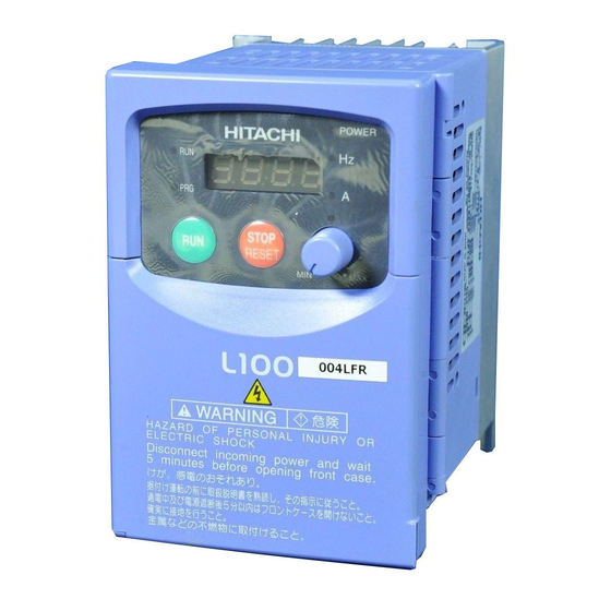
- Page 23 Introduction Inverter Specifications Label The Hitachi L100 inverters have product labels located on the right side of the housing, as pictured below. Be sure to verify that the specifications on the labels match your power source, motor, and application safety requirements.
-
Page 24: L100 Inverter Specifications
1–5 L100 Inverter L100 Inverter Specifications Model-specific tables for 200V and 400V class inverters The following tables are specific to L100 inverters for the 200V and 400V class model groups. Note that “General Specifications” on page 1–9 apply to both voltage class groups. - Page 25 The protection method conforms to JEM 1030. Note 2: The applicable motor refers to Hitachi standard 3-phase motor (4-pole). When using other motors, care must be taken to prevent the rated motor current (50/ 60 Hz) from exceeding the rated output current of the inverter.
- Page 26 1–7 L100 Inverter L100 Inverter Specifications, continued... Item 200V Class Specifications, continued L100 inverters, CE version 015NFE 022NFE — — — 200V models UL version 015NFU 022NFU 037LFU 055LFU 075LFU Applicable motor size *2 Rated capacity (240V) kVA *10 12.7 Rated input voltage 1-phase: 200 to 240V +5%/–10%, 50/60 Hz ±5%, 3-phase: 200 to 240V +5%/–10%, 50/60 Hz ±5%,...
- Page 27 1–8 L100 Inverter Specifications Item 400V Class Specifications L100 inverters, CE version 004HFE 007HFE 015HFE 022HFE 400V models UL version 004HFU 007HFU 015HFU 022HFU Applicable motor size *2 0.75 Rated capacity (460V) kVA *10 Rated input voltage 3-phase: 380 to 460V ±10%, 50/60 Hz ±5% Rated input current (A) Rated output voltage *3 3-phase: 380 to 460V (corresponding to input voltage)
-
Page 28: General Specifications
1–9 L100 Inverter Item 400V Class Specifications, continued L100 inverters, CE version 030HFE 040HFE 055HFE 075HFE 400V models UL version — 040HFU 055HFU 075HFU Applicable motor size *2 Rated capacity (460V) kVA *10 10.4 12.7 Rated input voltage 3-phase: 380 to 460V ±10%, 50/60 Hz ±5% Rated input current (A) 10.0 11.0... - Page 29 1–10 L100 Inverter Specifications Item General Specifications Input Freq. Operator panel Up and Down keys / Value settings signal setting Potentiometer Analog setting External signal 0 to 10 VDC (input impedance 10k Ohms), 4 to 20 mA (input impedance 250 Ohms), Potentiometer (1k to 2k Ohms, 2W) FWD/ Operator panel Run/Stop (Forward/Reverse run change by command) External signal Forward run/stop, Reverse run/stop...
- Page 30 1–11 L100 Inverter Signal Ratings Detailed ratings are in “Specifications of Control and Logic Connections” on page 4–6. Signal / Contact Ratings Built-in power for inputs 24VDC, 30 mA maximum Discrete logic inputs 27VDC maximum Discrete logic outputs 50mA maximum ON state current, 27 VDC maximum OFF state voltage PWM (analog/digital) output 0 to 10VDC, 1 mA, PWM and 50% duty digital Analog input, current...
- Page 31 1–12 L100 Inverter Specifications Derating Curves The maximum available inverter current output is limited by the carrier frequency and ambient temperature. The carrier frequency is the inverter’s internal power switching frequency, settable from 0.5 kHz to 16 kHz. Choosing a higher carrier frequency tends to decrease audible noise, but it also increases the internal heating of the inverter, thus decreasing (derating) the maximum current output capability.
-
Page 32: L100 Inverter Specifications
1–13 L100 Inverter Derating curves, continued... L100–007NFE/NFU 100% % of rated output current Carrier frequency L100–0015NFE/NFU 100% % of rated output current Carrier frequency L100–022NFE/NFU 100% % of rated output current Carrier frequency... - Page 33 1–14 L100 Inverter Specifications Derating curves, continued... L100–037LF/LFU 100% % of rated output current Carrier frequency L100–055LFU 100% % of rated output current Carrier frequency L100–075LFU 100% % of rated output current Carrier frequency...
- Page 34 1–15 L100 Inverter Derating curves, continued... L100–004HFE/HFU 100% % of rated output current Carrier frequency L100–007HFE/HFU 100% % of rated output current Carrier frequency L100–015HFE/HFU 100% % of rated output current Carrier frequency...
- Page 35 1–16 L100 Inverter Specifications Derating curves, continued... L100–022HFE/HFU 100% % of rated output current Carrier frequency L100–040HFE/HFU 100% % of rated output current Carrier frequency L100–055HFE/HFU 100% % of rated output current Carrier frequency...
- Page 36 1–17 L100 Inverter Derating curves, continued... L100–075HFE/HFU 100% % of rated output current Carrier frequency...
-
Page 37: Introduction To Variable-Frequency Drives
Introduction to Variable-Frequency Drives The Purpose of Motor Speed Control for Industry Hitachi inverters provide speed control for 3-phase AC induction motors. You connect AC power to the inverter, and connect the inverter to the motor. Many applications benefit from a motor with variable speed, in several ways: •... - Page 38 Inverter Input and Three-Phase Power The Hitachi L100 Series of inverters includes two sub-groups: the 200V class and the 400V class inverters. The drives described in this manual may be used in either the United States or Europe, although the exact voltage level for commercial power may be slightly different from country to country.
- Page 39 The Hitachi inverter is a rugged and reliable device. The intention is for the inverter to assume the role of controlling power to the motor during all normal operations. There- fore, this manual instructs you not to switch off power to the inverter while the motor is running (unless it is an emergency stop).
- Page 40 For loads that continuously overhaul the motor for extended periods of time, the L100 may not be suitable (contact your Hitachi distributor). The inverter parameters include acceleration and deceleration, which you can set to match the needs of the application.
- Page 41 1–22 Introduction to Variable-Frequency Drives Velocity Profiles The L100 inverter is capable of sophisticated speed control. A graphical representation of Set speed Speed that capability will help you understand and configure the associated parameters. This Accel Decel manual makes use of the velocity profile graph used in industry (shown at right).
-
Page 42: Frequently Asked Questions
1–23 L100 Inverter Frequently Asked Questions What is the main advantage in using an inverter to drive a motor, compared to alternative solutions? An inverter can vary the motor speed with very little loss of efficiency, unlike mechanical or hydraulic speed control solutions. The resulting energy savings usually pays for the inverter in a relatively short time. - Page 43 The greater the number of poles, the slower the top motor speed will be, but it will have higher torque at the base speed. Will I be able to add dynamic (resistive) braking to my Hitachi L100 drive after the initial installation? Yes.
- Page 44 Several options related to electrical noise suppression are available for the Hitachi inverters. How can I know if my application will require any of these options? The purpose of these noise filters is to reduce the inverter electrical noise so the operation of nearby electrical devices is not affected.
- Page 45 Inverter Mounting and Installation In This Chapter..page — Orientation to Inverter Features ...... — Basic System Description ....... — Step-by-Step Basic Installation......— Powerup Test ..........— Using the Front Panel Keypad ......
-
Page 46: Orientation To Inverter Features
2–2 Orientation to Inverter Features Orientation to Inverter Features Unpacking and Inspection Please take a few moments to unpack your new L100 inverter and perform these steps: 1. Look for any damage that may have occurred during shipping. 2. Verify the contents of the box include: a. - Page 47 2–3 L100 Inverter 2. Second-level access - Locate the lift tab at the right lower corner of the front panel near the safety warning message. Lift the corner to swing the half-door around to the left. This exposes four more control buttons and some connectors. The FUNC., , and STR keys allow an operator to access and change the inverter’s functions and parameter values.
- Page 48 2–4 Orientation to Inverter Features 3. Third-level access - First, ensure no power source of any kind is connected to the inverter. If power has been connected, wait five minutes after powerdown and verify the Power LED is OFF to proceed. Then locate the recessed retention screw on the left side main front panel (it is along the left hinge area on some models, or behind...
-
Page 49: Basic System Description
2–5 L100 Inverter Basic System Description A motor control system will obviously include a motor and inverter, as well as a breaker or fuses for safety. If you are connecting a motor to the inverter on a test bench just to get started, that’s all you may need for now. -
Page 50: Step-By-Step Basic Installation
2–6 Step-by-Step Basic Installation WARNING: In the cases below involving a general-purpose inverter, a large peak current can flow on the power supply side, sometimes destroying the converter module: 1.The unbalance factor of the power supply is 3% or higher. 2.The power supply capacity is at least 10 times greater than the inverter capacity (or the power supply capacity is 500 kVA or more). - Page 51 2–7 L100 Inverter Choosing a Mounting Location Step 1: Study the following caution messages associated with mounting the inverter. This is the time when mistakes are most likely to occur that will result in expensive rework, equipment damage, or personal injury. CAUTION: Be sure to install the unit on flame-resistant material such as a steel plate.
- Page 52 2–8 Step-by-Step Basic Installation Ensure Adequate Ventilation Step 2: To summarize the caution messages—you will need to find a solid, non-flamma- ble, vertical surface that is in a relatively clean and dry environment. In order to ensure enough room for air circulation around the inverter to aid in cooling, maintain the speci- fied clearance around the inverter specified in the diagram.
- Page 53 2–9 L100 Inverter 3. When installing the inverter in an enclosure, maintain the clearance around the inverter and verify that its ambient temperature is within specification when the enclosure door is closed. 4. Do not open the main front panel door at any time during operation. Check Inverter Dimensions Step 4: Locate the applicable drawing on the following pages for your inverter.
- Page 54 2–10 Step-by-Step Basic Installation Dimensional drawings, continued... 98(3.86) External Dimensions MODEL L100 -004HFE -004HFU -005NFE -007NFE -007NFU 5(0.20) 5(0.20) 110(4.33) 4(0.16) Ground Terminal 98(3.86) MODEL L100 -007HFE(No fan) -007HFU(No fan) -015HFE -015HFU 5(0.20) 5(0.20) 110(4.33) 4(0.16) Ground Terminal...
- Page 55 2–11 L100 Inverter Dimensional drawings, continued... 140(5.51) -011NFE L100 128(5.04) -015NFE -015NFU 5(0.20) 5(0.20) Ground Terminal 140(5.51) L100 -022NFE -022NFU 128(5.04) -022HFE -022HFU -030HFE -037LFU -040HFE -040HFU 5(0.20) 5(0.20) Ground Terminal...
- Page 56 2–12 Step-by-Step Basic Installation Dimensional drawings, continued... L100 -055LFU -075LFU -055HFU -075HFU -055HFE -075HFE 182(7.17) 160(6.30) 7(0.28) 7(0.28) Ground Terminal NOTE: Model L100-075LFU has (2) fans. All other models in this housing have (1) fan.
- Page 57 2–13 L100 Inverter Prepare for Wiring Step 5: It is very important to perform the wiring steps carefully and correctly. Before proceeding, please study the caution and warning messages below. WARNING: “Use 60/75°C Cu wire only” or equivalent. WARNING: “Open Type Equipment.” WARNING: “Suitable for use on a circuit capable of delivering not more than 5,000 rms symmetrical amperes, 240 V maximum.”...
- Page 58 2–14 Step-by-Step Basic Installation Determining Wire and Fuse Sizes The maximum motor currents in your application determines the recommended wire size. The following table gives the wire size in AWG. The “Power Lines” column applies to the inverter input power, output wires to the motor, the earth ground connec- tion, and any other component shown in the “Basic System Description”...
- Page 59 2–15 L100 Inverter Terminal Dimensions and Torque Specs The terminal screw dimensions for all L100 inverters are listed in table below. This information is useful in sizing spade lug or ring lug connectors for wire terminations. CAUTION: Fasten the screws with the specified fastening torque in the table below. Check for any loosening of screws.
- Page 60 2–16 Step-by-Step Basic Installation Please use the terminal arrangement below corresponding to your inverter model. –002NFE/NFU, –004NFE/NFU, –005NFE Jumper – L2 N/L3 U/T1 V/T2 W/T3 Chassis Ground –007 to 022NFE/NFU, –037LFU, 004 to 040HFE/HFU Jumper – L2 N/L3 U/T1 V/T2 W/T3 Chassis Ground...
- Page 61 2–17 L100 Inverter CAUTION: Be sure not to connect an AC power supply to the output terminals. Other- wise, there is the possibility of damage to the inverter and the danger of injury and/or fire. Power Input Power Output NOTE: T1 T2 T3 L, N: Single-phase 200 to 240V 50/60 Hz...
- Page 62 2–18 Step-by-Step Basic Installation Wire the Inverter Output to Motor Step 7: The process of motor selection is beyond the scope of this manual. However, it must be an AC induction motor with three phases. It should also come with a chassis ground lug.
-
Page 63: Powerup Test
3. Give a brief introduction to the use of the built-in operator keypad. The powerup test gives you an important starting point to ensure a safe and successful application of the Hitachi inverter. We highly recommend performing this test before proceeding to the other chapters in this manual. - Page 64 2–20 Powerup Test Pre-test and Operational Precautions The following instructions apply to the powerup test, or to any time the inverter is powered and operating. Please study the following instructions and messages before proceeding with the powerup test. 1. The power supply must have fusing suitable for the load. Check the fuse size chart presented in Step 5, if necessary.
-
Page 65: Using The Front Panel Keypad
Please take a moment to familiarize yourself with the keypad layout shown in the figure below. These are the visible controls and indicators when the front panel door is closed. Power LED Parameter Display POWER HITACHI Run/Stop LED Display Units 5 0.0 Hertz / Amperes LEDs... - Page 66 2–22 Using the Front Panel Keypad • Parameter Display - A 4-digit, 7-segment display for parameters and function codes. • Display Units, Hertz/Amperes - One of these LEDs will be ON to indicate the units associated with the parameter display. •...
- Page 67 2–23 L100 Inverter Keypad Navigational Map The L100 Series inverter drives have many programmable functions and parameters. Chapter 3 will cover these in detail, but you need to access just a few items to perform the powerup test. The menu structure makes use of function codes and parameter codes to allow programming and monitoring with only a 4-digit display and a few keys and LEDs.
- Page 68 2–24 Using the Front Panel Keypad Selecting Functions and Editing Parameters In order to run the motor for the powerup test, this section will show how to: • select the inverter’s maximum output frequency to the motor • select the keypad potentiometer as the source of motor speed command •...
- Page 69 2–25 L100 Inverter Select the Potentiometer for Speed Command - The motor speed may be controlled from the following sources: • Potentiometer on front panel keypad • Control terminals • Remote panel Then follow the steps in the table below to select the potentiometer for the speed command (the table resumes action from the end of the previous table).
- Page 70 Monitoring Parameters with the Display After using the keypad for parameter editing, it’s a good idea to switch the inverter from POWER HITACHI Program Mode to Monitor Mode and close 5 0.0 the panel door (puts the keys for parameter editing out of sight).
- Page 71 NOTE: Some factory automation devices such as PLCs have alternate Run/Program modes; the device is in either one mode or the other. In the Hitachi inverter, however, Run Mode alternates with Stop Mode, and Program Mode alternates with Monitor Mode.
- Page 72 Configuring Drive Parameters In This Chapter..page — Choosing a Programming Device ....— Using Keypad Devices ........— “D” Group: Monitoring Functions..... — “F” Group: Main Profile Parameters ....— “A” Group: Standard Functions ....... — “B” Group: Fine Tuning Functions ....
-
Page 73: Choosing A Programming Device
Choosing a Programming Device Introduction Hitachi variable frequency drives (inverters) use the latest electronics technology for getting the right AC waveform to the motor at the right time. The benefits are many, including energy savings and higher machine output or productivity. The flexibility required to handle a broad range of applications has required ever more configurable options and parameters—inverters are now a complex industrial automation component. -
Page 74: Using Keypad Devices
The keypad layout is pictured below. All other programming devices for the inverter have a similar key arrangement and function. Power LED Parameter Display POWER HITACHI Run/Stop LED Display Units 5 0.0 Hertz / Amperes LEDs Program/Monitor LED... - Page 75 3–4 Using Keypad Devices Keypad Navigational Map You can use the inverter’s front panel keypad to navigate to any parameter or function. The diagram below shows the basic navigational map to access these items. Monitor Mode Program Mode PRG LED=OFF PRG LED=ON Display Data Select Parameter...
- Page 76 3–5 L100 Inverter Operational Modes The RUN and PGM LEDs tell just part of the story; STOP Run Mode and Program Modes are independent RESET Stop modes, not opposite modes. In the state diagram to the right, Run alternates with Stop, and Program Mode alternates with Monitor Mode.
-
Page 77: D" Group: Monitoring Functions
3–6 “D” Group: Monitoring Functions “D” Group: Monitoring Functions Parameter Monitoring Functions You can access important system parameter values with the “D” Group monitoring functions, whether the inverter is in Run Mode or Stop Mode. After selecting the function code number for the parameter you want to monitor, press the Function key once to show the value on the display. - Page 78 3–7 L100 Inverter “D” Function Range Mode Func. Name / Description Edit Units Code SRW Display D_07 Scaled output frequency Displays the output frequency — monitor scaled by the constant in B_86. Decimal point indicates range: /Hz01.0 0.00 XX.XX 0.01 to 99.99 XXX.X 100.0 to 999.9 XXXX.
-
Page 79: F" Group: Main Profile Parameters
3–8 “F” Group: Main Profile Parameters “F” Group: Main Profile Parameters The basic frequency (speed) profile is Output defined by parameters contained in the “F” F 02 F 03 frequency Group as shown to the right. The set running frequency is in Hz, but accelera- F 01 tion and deceleration are specified in the time duration of the ramp (from zero to... -
Page 80: A" Group: Standard Functions
3–9 L100 Inverter “A” Group: Standard Functions Basic Parameter Settings These settings affect the most fundamental behavior of the inverter—the outputs to the motor. The frequency of the inverter’s AC output determines the motor speed. You may select from three different sources for the reference speed. During application develop- ment you may prefer using the potentiometer, but you may switch to an external source (control terminal setting) in the finished application, for example. -
Page 81: Functions
3–10 “A” Group: Standard Functions Analog Input Settings The inverter has the capability to accept an external analog input that can command the output frequency to the motor. Voltage input (0 –10V) and current input (4–20mA) are available on separate terminals ([O] and [OI], respectively). Terminal [L] serves as signal ground for the two analog inputs. - Page 82 3–11 L100 Inverter “A” Function Defaults Mode Func. Name / –FE –FU –FR Description Units Edit Code SRW Display (CE) (UL) (Jpn) ✘ A_16 External frequency Range n = 1 to 8, where n = Sam- filter time constant number of samples for avg. ples IN F-SAMP...
- Page 83 3–12 “A” Group: Standard Functions Multi-speed and Jog Frequency Setting The L100 inverter has the capability to store and output up to 16 preset frequencies to the motor (A_20 to A_35). As in traditional motion terminology, we call this multi-speed profile capability.
- Page 84 3–13 L100 Inverter Torque Control Algorithms The inverter generates the motor output Inverter Torque Control Algorithms according to the V/f algorithm selected. Parameter A_44 selects the inverter algorithm V/f control, for generating the frequency output, as shown constant torque in the diagram to the right. The factory Output default is 00 (constant torque).
- Page 85 3–14 “A” Group: Standard Functions Voltage Gain – Using parameter A_45 you Voltage Gain can modify the voltage gain of the inverter (see 100% graph at right). This is specified as a percent- age of the full scale setting (Automatic Voltage A 45 Regulation) AVR level in parameter F_03.
- Page 86 3–15 L100 Inverter DC Braking Settings The DC braking feature can provide additional stopping torque when Running Free run DC braking compared to a normal deceleration to a stop. DC braking is particularly useful at low speeds when normal decelera- tion torque is minimal.
- Page 87 3–16 “A” Group: Standard Functions Frequency-related Functions Frequency Limits – Upper and lower Output limits can be imposed on the inverter frequency output frequency. These limits will apply Upper regardless of the source of the speed refer- A 61 limit ence.
- Page 88 3–17 L100 Inverter Jump Frequencies – Some motors or machines exhibit resonances at particular speed(s), which can be destructive for prolonged running at those speeds. The inverter has up to three jump frequencies as shown in the graph. The hysteresis around the jump frequencies causes the inverter output to skip around the sensitive frequency values Output frequency...
- Page 89 3–18 “A” Group: Standard Functions PID Control When enabled, the built-in PID loop calculates an ideal inverter output value to cause a loop feedback process variable (PV) to move closer in value to the setpoint (SP). The current frequency command serves as the SP. The PID loop algorithm will read the analog input for the process variable (you specify the current or voltage input) and calcu- late the output.
- Page 90 3–19 L100 Inverter Automatic Voltage Regulation (AVR) Function The automatic voltage regulation (AVR) feature keeps the inverter output waveform at a relatively constant amplitude during power input fluctuations. This can be useful if the installation is subject to input voltage fluctuations. However, the inverter cannot boost its motor output to a voltage higher than the power input voltage.
- Page 91 3–20 “A” Group: Standard Functions Second Acceleration and Deceleration Functions The L100 inverter features two-stage acceleration and deceleration ramps. This gives flexibility in the profile shape. You can specify the frequency transition point, the point at which the standard acceleration (F_02) or deceleration (F_03) changes to the second acceleration (A_92) or deceleration (A_93).
- Page 92 3–21 L100 Inverter Accel/Decel Standard acceleration and deceleration is Output linear. The inverter CPU can also calculate frequency Accel. curve selection an S-curve acceleration or deceleration curve as shown. This profile is useful for Target freq. favoring the load characteristics in particu- lar applications.
-
Page 93: B" Group: Fine Tuning Functions
3–22 “B” Group: Fine Tuning Functions “B” Group: Fine Tuning Functions The “B” Group of functions and parameters adjust some of the more subtle but useful aspects of motor control and system configuration. Automatic Restart Mode The restart mode determines how the inverter will resume operation after a fault causes a trip event. - Page 94 3–23 L100 Inverter “B” Function Defaults Mode Func. Name / –FE –FU –FR Description Units Edit Code SRW Display (CE) (UL) (Jpn) ✘ B_01 Selection of restart Select inverter restart method, — mode four option codes: 00 ...Alarm output after trip, IPS POWR no automatic restart 01 ...Restart at 0Hz...
- Page 95 3–24 “B” Group: Fine Tuning Functions Electronic Thermal Overload Alarm Setting The thermal overload detection protects the Torque inverter and motor from overheating due to Constant torque B_13 = 01 100% an excessive load. It uses a current/inverse time curve to determine the trip point. Reduced torque First, use B_13 to select the torque charac-...
- Page 96 3–25 L100 Inverter Overload Restriction If the inverter’s output current exceeds a Motor preset current level you specify during Current acceleration or constant speed, the overload Restriction area B 22 restriction feature automatically reduces the output frequency to restrict the overload. This feature does not generate an alarm or trip event.
- Page 97 3–26 “B” Group: Fine Tuning Functions Software Lock Mode The software lock function keeps personnel from accidentally changing parameters in the inverter memory. Use B_31 to select from various protection levels. The table below lists all combinations of B_31 option codes and the ON/OFF state of the [SFT] input.
- Page 98 3–27 L100 Inverter “B” Function Defaults Mode Func. Name / –FE –FU –FR Description Units Edit Code SRW Display (CE) (UL) (Jpn) ✘ B_31 Software lock mode Prevents parameter changes, in — selection four options, option codes: 00 ...all parameters except S-LOCK B_31 are locked when [SFT] terminal is ON...
- Page 99 3–28 “B” Group: Fine Tuning Functions Miscellaneous Settings The miscellaneous settings include scaling factors, initialization modes, and others. This section covers some of the most important settings you may need to configure. B_32: Reactive current setting – The inverter’s D_02 monitor function displays the motor current.
- Page 100 3–29 L100 Inverter NOTE: When DC braking is performed, the inverter automatically holds the carrier frequency at 1 kHz. NOTE: The carrier frequency setting must stay within specified limits for inverter-motor applications that must comply with particular regulatory agencies. For example, a European CE-approved application requires the inverter carrier to be less than 5 kHz.
- Page 101 3–30 “B” Group: Fine Tuning Functions “B” Function Defaults Mode Func. Name / –FE –FU –FR Description Units Edit Code SRW Display (CE) (UL) (Jpn) ✘ B_86 Frequency scaling Specify a constant to scale the — conversion factor displayed frequency for D_07 monitor, range is 0.1 to 99.9 /Hz01.0 0.00...
- Page 102 3–31 L100 Inverter “B” Function Defaults Mode Func. Name / –FE –FU –FR Description Units Edit Code SRW Display (CE) (UL) (Jpn) ✘ B_88 Restart mode after FRS Selects how the inverter — resumes operation when the RUN FRS free-run stop (FRS) is cancelled, two options: 00...
-
Page 103: C" Group: Intelligent Terminal Functions
3–32 “C” Group: Intelligent Terminal Functions “C” Group: Intelligent Terminal Functions The five input terminals [1], [2], [3], [4], and [5] can be configured for any of fifteen different functions. The next two tables show how to configure the five terminals. The inputs are logical, in that they are either OFF or ON. - Page 104 3–33 L100 Inverter The input logic convention is programmable for each of the five inputs. Most inputs default to normally open (active high), but you can select normally closed (active low) in order to invert the sense of the logic. “C”...
- Page 105 3–34 “C” Group: Intelligent Terminal Functions Input Function Summary Table – This table shows all fifteen intelligent input functions at a glance. Detailed descriptions of these functions, related parameters and settings, and example wiring diagrams are in “Using Intelligent Input Terminals” on page 4–8.
- Page 106 3–35 L100 Inverter Input Function Summary Table Option Terminal Function Name Description Code Symbol Software Lock The keypad and remote programming devices are prevented from changing parameters The parameters may be edited and stored Analog Input Terminal [OI] is enabled for current input (uses Voltage/current terminal L for power supply return) Select...
- Page 107 3–36 “C” Group: Intelligent Terminal Functions Output Terminal Configuration The inverter provides configuration for logic (discrete) and analog outputs, shown in the table below. “C” Function Defaults Mode Func. Name / –FE –FU –FR Description Units Edit Code SRW Display (CE) (UL) (Jpn)
- Page 108 3–37 L100 Inverter Output Function Summary Table – This table shows all six functions for the logical outputs (terminals [11], [12]) at a glance. Detailed descriptions of these functions, related parameters and settings, and example wiring diagrams are in “Using Intelligent Output Terminals”...
- Page 109 3–38 “C” Group: Intelligent Terminal Functions Analog Function Summary Table – This table shows all three functions for the analog output [FM] (frequency meter) terminal. Detailed descriptions, related parameters and settings, and example wiring diagrams are in “Analog and Digital Monitor Output” on page 4–30.
- Page 110 3–39 L100 Inverter Output Function Adjustment Parameters The following parameters work in Motor current conjunction with the intelligent output C 41 function, when configured. The overload level parameter (C_41) sets the motor current level at which the overload signal [OL] turns ON. The range of settings is Overload signal from 0% to 200% of the rated current for...
- Page 111 3–40 “C” Group: Intelligent Terminal Functions “C” Function Defaults Mode Func. Name / –FE –FU –FR Description Units Edit Code SRW Display (CE) (UL) (Jpn) ✘ C_43 Arrival frequency Sets the frequency arrival setting for deceleration setting threshold for the output frequency during deceleration ARV DEC 000.0Hz...
- Page 112 Operations and Monitoring In This Chapter..page — Introduction ............. — Connecting to PLCs and Other Devices ..— Using Intelligent Input Terminals ..... — Using Intelligent Output Terminals ....— Analog Input Operation ......... — Analog and Digital Monitor Output ....
-
Page 113: Introduction
4–2 Introduction Introduction The previous material in Chapter 3 gave a reference listing of all the programmable functions of the inverter. We suggest that you first scan through the listing of inverter functions to gain a general familiarity. This chapter will build on that knowledge in the following ways: 1. - Page 114 4–3 L100 Inverter Warning Messages for Operating Procedures Before continuing, please read the following Warning messages. WARNING: Be sure to turn ON the input power supply only after closing the front case. While being energized, be sure not to open the front case. Otherwise, there is the danger of electric shock.
-
Page 115: Connecting To Plcs And Other Devices
Connecting to PLCs and Other Devices Connecting to PLCs and Other Devices Hitachi inverters (drives) are useful in many types of applications. During installation, the inverter keypad (or other programming device) will facilitate the initial configura- tion. After installation, the inverter will generally receive its control commands through the control logic connector or serial interface from another controlling device. -
Page 116: Example Wiring Diagram
4–5 L100 Inverter Example Wiring Diagram The schematic diagram below provides a general example of logic connector wiring, in addition to basic power and motor wiring covered in Chapter 2. The goal of this chapter is to help you determine the proper connections for the various terminals shown below for your specific application needs. - Page 117 4–6 Example Wiring Diagram Specifications of Control and Logic Connections The control logic connectors are located just behind the front panel half-door. The relay contacts are accessible behind the main door. Connector labeling is shown below. Logic inputs H O OI FM CM2 12 11 Relay...
- Page 118 4–7 L100 Inverter Terminal Listing Use the following tables to locate pages for intelligent input and output material in this chapter. Intelligent Inputs Symbol Code Name Page Forward Run/Stop 4–9 Reverse Run/Stop 4–9 Multi-speed Select, Bit 0 (LSB) 4–10 Multi-speed Select, Bit 1 4–10 Multi-speed Select, Bit 2 4–10...
-
Page 119: Using Intelligent Input Terminals
4–8 Using Intelligent Input Terminals Using Intelligent Input Terminals Terminals [1], [2], [3], [4], and [5] are identical, programmable inputs for general use. The input circuits can use the inverter’s internal (isolated) +24V field supply (P24) to power the inputs. The input circuits are internally connected to the power supply ground. As the diagram shows, you can use a switch (or jumper) to activate an input terminal that has been configured. - Page 120 4–9 L100 Inverter Forward Run/Stop and Reverse Run/Stop Commands: When you input the Run command via the terminal [FW], the inverter executes the Forward Run command (high) or Stop command (low). When you input the Run command via the terminal [RV], the inverter executes the Reverse Run command (high) or Stop command (low).
- Page 121 4–10 Using Intelligent Input Terminals Multi-Speed Select The inverter can store up to 16 different target frequencies (speeds) that the motor output uses for Input Function steady-state run condition. These speeds are acces- Multi- speed sible through programming four of the intelligent CF4 CF3 CF2 CF1 terminals as binary-encoded inputs CF1 to CF4 per Speed 0...
- Page 122 4–11 L100 Inverter Option Terminal Input Function Name Description Code Symbol State C_01, C_02, C_03, C_04, Example (some CF inputs require input Valid for inputs: C_05 configuration; some are default inputs— see page 3–32): F_01, A_01 = 02, Required settings: (MSB) (LSB) A_20 to A_35...
- Page 123 4–12 Using Intelligent Input Terminals Jogging Command The Jog input [JG] is used to command the [JG] motor to rotate slowly in small increments for manual operation. The speed is limited to [FW], [RV] 10 Hz. The frequency for the jogging opera- tion is set by parameter A_38.
- Page 124 4–13 L100 Inverter Two-stage Acceleration and Deceleration When terminal [2CH] is turned ON, the Output target inverter changes the rate of acceleration and frequency frequency deceleration from the initial settings (F_02 second and F_03) to use the second set of accelera- initial tion/deceleration values.
-
Page 125: Free-Run Stop
4–14 Using Intelligent Input Terminals Free-run Stop When the terminal [FRS] is turned ON, the inverter stops the output and the motor enters the free-run state (coasting). If terminal [FRS] is turned OFF, the output resumes sending power to the motor if the Run command is still active. The free-run stop feature works with other parameters to provide flexibility in stopping and starting motor rotation. -
Page 126: External Trip
4–15 L100 Inverter External Trip When the terminal [EXT] is turned ON, the inverter enters the trip state, indicates error code E12, and stops the output. This is a general purpose interrupt type feature, and the meaning of the error depends on what you connect to the [EXT] terminal. Even if the [EXT] input is turned OFF, the inverter remains in the trip state. -
Page 127: Unattended Start Protection
4–16 Using Intelligent Input Terminals Unattended Start Protection If the Run command is already set when power is turned ON, the inverter starts running immediately after powerup. The Unattended Start Protection (USP) function prevents that automatic startup, so that the inverter will not run without outside intervention. When USP is active and you need to reset an alarm and resume running, either turn the Run command OFF, or perform a reset operation by the terminal [RS] input or the keypad Stop/reset key. -
Page 128: Software Lock
4–17 L100 Inverter Software Lock When the terminal [SFT] is turned ON, the data of all the parameters and functions (except the output frequency, depending on the setting of B_31) is locked (prohibited from editing). When the data is locked, the keypad keys cannot edit inverter parameters. To edit parameters again, turn OFF the [SFT] terminal input. - Page 129 4–18 Using Intelligent Input Terminals Analog Input Current/Voltage Select The [AT] terminal selects whether the inverter uses the voltage [O] or current [OI] input terminals for external frequency control. When intelligent input [AT] is ON, you can set the output frequency by applying a current input signal at [OI]-[L]. When the [AT] input is OFF, you can apply a voltage input signal at [O]-[L] to set the output frequency.
-
Page 130: Reset Inverter
4–19 L100 Inverter Reset Inverter The [RS] terminal causes the inverter to 12 ms execute the reset operation. If the inverter is minimum in Trip Mode, the reset cancels the Trip state. [RS] When the signal [RS] is turned ON and OFF, approx. -
Page 131: Thermistor Thermal Protection
4–20 Using Intelligent Input Terminals Thermistor Thermal Protection Motors that are equipped with a thermistor can be protected from overheating. Input terminal [5] has the unique ability to sense a thermistor resistance. When the resistance value of the thermistor connected to terminal [TH] (5) and [L] is more than 3 k Ohms ±10%, the inverter enters the Trip Mode, turns OFF the output to the motor, and indicates the trip status E35. -
Page 132: Using Intelligent Output Terminals
4–21 L100 Inverter Using Intelligent Output Terminals The intelligent output terminals are programmable in a similar way to the intelligent input terminals. The inverter has several output functions that you can assign individu- ally to three physical logic outputs. Two of the outputs are open-collector transistors, and the third output is the alarm relay (form C –... -
Page 133: Run Signal
4–22 Using Intelligent Output Terminals Run Signal When the [RUN] signal is selected as an [FW], intelligent output terminal, the inverter [RV] outputs a signal on that terminal when it is in Run Mode. The output logic is active low, and B 82 is the open collector type (switch to ground). - Page 134 4–23 L100 Inverter Frequency Arrival Signals The Frequency Arrival group of outputs help coordinate external systems with the current velocity profile of the inverter. As the name implies, output [FA1] turns ON when the output frequency arrives at the standard set frequency (parameter F_01). Output [FA2] relies on programmable accel/ decel thresholds for increased flexibility.
- Page 135 4–24 Using Intelligent Output Terminals Frequency arrival output [FA1] uses the Output standard output frequency (parameter 1.5 Hz freq. F_01) as the threshold for switching. In 0.5 Hz F 01 F 01 the figure to the right, Frequency Arrival 1.5 Hz [FA1] turns ON when the output 0.5 Hz frequency gets within 0.5 Hz below or...
-
Page 136: Overload Advance Notice Signal
4–25 L100 Inverter Overload Advance Notice Signal When the output current exceeds a preset Current threshold value, the [OL] terminal signal turns ON. C 41 power running The parameter C_41 sets the overload threshold. The overload detection circuit C 41 regeneration operates during powered motor opera- threshold... -
Page 137: Output Deviation For Pid Control
4–26 Using Intelligent Output Terminals Output Deviation for PID Control The PID loop error is defined as the SP, PV Process variable magnitude (absolute value) of the differ- ence between the Setpoint (target value) C 44 Setpoint and the Process Variable (actual value). When the error magnitude exceeds the C 44 preset value for C_44, the [OD] terminal... -
Page 138: Alarm Signal
4–27 L100 Inverter Alarm Signal The inverter alarm signal is active when a fault has STOP occurred and it is in the Trip Mode (refer to the RESET Stop diagram at right). When the fault is cleared the alarm signal becomes inactive. STOP RESET We must make a distinction between the alarm... - Page 139 4–28 Using Intelligent Output Terminals The alarm output terminals are connected as shown below (left) by default. The contact logic can be inverted as shown (below right) by using the parameter setting C_33. The relay contacts normally open (N.O.) and normally closed (N.O.) convention uses “normal”...
-
Page 140: Analog Input Operation
4–29 L100 Inverter Analog Input Operation The L100 inverters provide for analog input H O OI FM CM2 12 11 to command the inverter frequency output +V Ref. value. The analog input terminal group includes the [L], [OI], [O], and [H] terminals Voltage input on the control connector, which provide for Current input... -
Page 141: Analog And Digital Monitor Output
4–30 Analog and Digital Monitor Output Analog and Digital Monitor Output In the system design for inverter applications it is useful to monitor the inverter opera- tion from a remote location. In some cases, this requires only a panel-mounted analog meter (moving-coil type). - Page 142 4–31 L100 Inverter TIP: When using the analog meter for monitoring, adjust the meter so it has a zero reading when the [FM] output is zero. Then use scale factor B_81 to adjust the [FM] output so the maximum frequency in the inverter corresponds to a full-scale reading on the meter.
-
Page 143: Pid Loop Operation
4–32 PID Loop Operation PID Loop Operation In standard operation, the inverter uses a reference source selected by parameter A_01 for the output frequency, which may be a fixed value (F_01), a variable set by the front panel potentiometer, or value from an analog input (voltage or current). To enable PID operation, set A_71 = 01. -
Page 144: Configuring The Inverter For Multiple Motors
4–33 L100 Inverter Configuring the Inverter for Multiple Motors Simultaneous Connections For some applications, you may need to connect two or more motors (wired in parallel) to a single inverter’s output. For example, this is common in conveyor applications where two separate conveyors L100 need to have approximately the same speed. -
Page 145: Chapter 5: Inverter System Accessories
Inverter System Accessories In This Chapter..page — Introduction ............. — Component Descriptions......... — Dynamic Braking .......... - Page 146 5–3 ALI–x2–xxx LPF–xxx R–2–xxx RF noise Note: The Hitachi part number series for accesso- filter ries includes different sizes of each part type, specified by the –x suffix. Hitachi product litera- AC reactor, or ture can help match size and rating of your LCR filter inverter to the proper accessory size.
-
Page 147: Component Descriptions
5–3 L100 Inverter Component Descriptions AC Reactors, Input Side This is useful in suppressing harmonics induced on the power supply lines, or when the main power voltage imbalance exceeds 3% (and power source capacity is more than 500 kVA), or to smooth out line fluctuations. It also improves the power factor. In the following cases for a general-purpose inverter, a large peak current flows on the main power supply side, and is able to destroy the inverter module: •... - Page 148 5–4 Component Descriptions Zero-phase Reactor (RF Noise Filter) The zero-phase reactor helps reduce radiated noise from the inverter wiring. It can be used on the input or output side of the inverter. The example zero-phase reactor shown to the right comes with a mounting bracket.
-
Page 149: Dynamic Braking
5–5 L100 Inverter Dynamic Braking Introduction The purpose of dynamic braking is to improve the ability of the inverter to stop (deceler- ate) the motor and load. This becomes necessary when an application has some or all of the following characteristics: •... - Page 150 5–6 Dynamic Braking Use one BRD–E2 braking unit for the braking torque listed in the following table. Note the column meanings in the tables: • Column “A” = Average braking torque from 60 Hz to 3 Hz. • Column “B” = Average braking torque from 120 Hz to 3 Hz L100 Inverter 200V Models Braking Torque with BRD–E2 Braking Unit External resistor added...
- Page 151 5–7 L100 Inverter 400V Class Inverters – The following tables Braking specify the braking options for 400V class unit L100 inverters and the braking torque for each Inverter option. You can connect a single braking unit to the inverter, or two braking units for Braking additional braking torque.
-
Page 152: Troubleshooting
Troubleshooting and Maintenance In This Chapter..page — Troubleshooting..........— Monitoring Trip Events, History, & Conditions — Restoring Factory Default Settings ....— Maintenance and Inspection ......— Warranty............ -
Page 153: Troubleshooting
6–2 Troubleshooting Troubleshooting Safety Messages Please read the following safety messages before troubleshooting or performing mainte- nance on the inverter and motor system. WARNING: Wait at least five (5) minutes after turning OFF the input power supply before performing maintenance or an inspection. Otherwise, there is the danger of electric shock. -
Page 154: Troubleshooting Tips
6–3 L100 Inverter Troubleshooting Tips The table below lists typical symptoms and the corresponding solution(s). Symptom/condition Probable Cause Solution • • Is the frequency command source Make sure the parameter A_01 parameter setting correct? setting A_01 is correct. • • Is the Run command source A_02 Make sure the parameter parameter setting correct? - Page 155 6–4 Troubleshooting Symptom/condition Probable Cause Solution • • If using the analog input, is the Check the wiring. current or voltage at [O] or [OI]? • Check the potentiometer or signal generating device. • • Is the load too heavy? Reduce the load.
-
Page 156: Monitoring Trip Events, History, & Conditions
6–5 L100 Inverter Monitoring Trip Events, History, & Conditions Fault Detection and Clearing The microprocessor in the inverter detects a variety STOP of fault conditions and captures the event, record- RESET Stop ing it in a history table. The inverter output turns OFF, or “trips”... - Page 157 6–6 Monitoring Trip Events, History, & Conditions Error Name Cause(s) Code E 1 2 External trip A signal on an intelligent input terminal configured as EXT has occurred. The inverter trips and turns OFF the output to the motor. E 1 3 When the Unattended Start Protection (USP) is enabled, an error occurred when power is applied while a Run signal is present.
- Page 158 6–7 L100 Inverter Trip History and Inverter Status We recommend that you first find the cause of the fault before clearing it. When a fault occurs, the inverter stores important performance data at the moment of the fault. To access the data, use the monitor functions (D_xx) and select D_08 for details about the present fault (E ), or the error code for the past two trip events (E and E...
-
Page 159: Restoring Factory Default Settings
6–8 Restoring Factory Default Settings Restoring Factory Default Settings You can restore all inverter parameters to the original factory (default) settings for the intended country of use. After initializing the inverter, use the powerup test in Chapter 2 to get the motor running again. To initialize the inverter, follow the steps below. Action Display Func./Parameter... -
Page 160: Maintenance And Inspection
6–9 L100 Inverter Maintenance and Inspection Monthly and Yearly Inspection Chart Inspection Cycle Inspection Item Inspected Check for... Criteria Method Month Year ✔ Ambient Extreme Thermometer, Ambient temperature environment temperatures hygrometer between -10 to 40°C, & humidity non-condensing ✔ Major devices Abnormal Visual and aural Stable environment for... - Page 161 6–10 Maintenance and Inspection Megger Test The megger is a piece of test equipment that uses a high voltage to determine if an insulation degradation has occurred. For inverters, it is important that the power termi- nals be isolated from the Earth GND terminal via the proper amount of insulation. The circuit diagram below shows the inverter wiring for performing the megger test.
-
Page 162: Spare Parts
6–11 L100 Inverter Spare parts We recommend that you stock spare parts to reduce down time, including these parts: Quantity Part description Symbol Notes Used Spare Cooling fan 022NF, 037LF, 015HF to 075HF Case • Front case • Key cover •... - Page 163 6–12 Maintenance and Inspection General Inverter Electrical Measurements The following table specifies how to measure key system electrical parameters. The diagrams on the next page show inverter-motor systems and the location of measure- ment points for these parameters. Circuit location Measuring Parameter Notes...
- Page 164 6–13 L100 Inverter The figures below show measurement locations for voltage, current, and power measure- ments listed in the table on the previous page. The voltage to be measured is the funda- mental wave effective voltage. The power to be measured is the total effective power. Single-phase Measurement Diagram Inverter Motor...
- Page 165 6–14 Maintenance and Inspection Inverter Output Voltage Measurement Techniques Taking voltage measurements around drives equipment requires the right equipment and a safe approach. You are working with high voltages and high-frequency switching waveforms that are not pure sinusoids. Digital voltmeters will not usually produce reliable readings for these waveforms.
- Page 166 6–15 L100 Inverter IGBT Test Method The following procedure will check the inverter transistors (IGBTs) and diodes: 1. Disconnect input power to terminals [R, S, and T] and motor terminals [U, V, and W]. 2. Disconnect any wires from terminals [+] and [–] for regenerative braking. 3.
-
Page 167: Warranty
(2) years from the date of manufacture (“DATE” on product nameplate), or one (1) year from the date of installation, whichever occurs first. The warranty shall cover the repair or replacement, at Hitachi's sole discretion, of ONLY the inverter that was installed. -
Page 168: Appendix A: Glossary And Bibliography
Glossary and Bibliography In This Appendix..page — Glossary ............— Bibliography ............ - Page 169 Auto-tuning is a common feature of process controllers with PID loops. Hitachi inverters feature auto tuning to determine motor parameters for optimal commutation. Auto-tuning is avail- able as a special command from a digital operator panel. See also Digital Operator Panel.
- Page 170 Digital Operator Panel For Hitachi inverters, “digital operator panel” (DOP) refers first to the operator keypad on the front panel of the inverter. It also includes hand-held remote keypads, which connect to the inverter via a cable.
- Page 171 Insulated Gate Bipolar Transistor (IGBT) – A semiconductor transistor capable of conducting very large currents when in satura- tion and capable of withstanding very high voltages when it is OFF. This high-power bipolar transistor is the type used in Hitachi invert- ers. Inertia The natural resistance a stationary object to being moved by an external force.
- Page 172 The ability of a motor drive to store preset discrete speed levels for the motor, and control motor speed according to the currently selected speed preset. The Hitachi inverters have 16 preset speeds. Motor Load In motor terminology, motor load consists of the inertia of the physical mass that is moved by the motor and the related friction from guiding mechanisms.
- Page 173 A–6 Glossary Pulse-width modulation: A type of AC adjustable frequency drive that accomplishes frequency and voltage control at the output section (inverter) of the drive. The drive output voltage waveform is at a constant amplitude, and by “chopping” the waveform (pulse- width-modulating), the average voltage is controlled.
- Page 174 Hot varies sinusoidally above and below Neutral. This power source is named Single Phase to differentiate it from three-phase power sources. Some Hitachi inverters can accept single phase input power, but they all output three-phase power to the motor. See also Three-phase.
- Page 175 The saturation voltage has been decreasing, resulting in less heat dissipation. Hitachi inverters use state-of-the- art semiconductors to provide high performance and reliability in a compact package. See also IGBT and Saturation Voltage.
-
Page 176: Appendix B: Drive Parameter Settings Tables
Drive Parameter Settings Tables In This Appendix..page — Introduction ............. — Parameter Settings for Keypad Entry.... -
Page 177: Parameter Settings For Keypad Entry
B–2 Introduction Introduction This appendix lists the user-programmable parameters for the L100 series inverters and the default values for European and U.S. product types. The right-most column of the tables is blank, so you can record values you have changed from the default. This involves just a few parameters for most applications. - Page 178 B–3 L100 Inverter Standard Functions “A” Group Parameters Default Setting User Func. –FR Setting Name Code (Europe) (USA) (Japan) A_01 Frequency source setting A_02 Run command source setting A_03 Base frequency setting 50.0 60.0 60.0 A_04 Maximum frequency setting 50.0 60.0 60.0 A_11...
- Page 179 B–4 Parameter Settings for Keypad Entry “A” Group Parameters Default Setting User Func. –FR Setting Name Code (Europe) (USA) (Japan) A_38 Jog frequency setting A_39 Jog stop mode A_41 Torque boost method selection A_42 Manual torque boost value A_43 Manual torque boost frequency 10.0 10.0 10.0...
- Page 180 B–5 L100 Inverter “A” Group Parameters Default Setting User Func. –FR Setting Name Code (Europe) (USA) (Japan) A_94 Select method to switch to second accel/decel profile A_95 Acc1 to Acc2 frequency transi- tion point A_96 Dec1 to Dec2 frequency transi- tion point A_97 Acceleration curve selection...
- Page 181 B–6 Parameter Settings for Keypad Entry Fine Tuning Functions “B” Group Parameters Default Setting User Func. –FR Setting Name Code (Europe) (USA) (Japan) B_01 Selection of automatic restart mode B_02 Allowable under-voltage power failure time B_03 Retry wait time before motor restart B_12 Level of electronic thermal...
- Page 182 B–7 L100 Inverter Intelligent Terminal Functions “C” Group Parameters Default Setting User Func. –FR Setting Name Code (Europe) (USA) (Japan) C_01 Terminal [1] function C_02 Terminal [2] function C_03 Terminal [3] function C_04 Terminal [4] function C_05 Terminal [5] function C_11 Terminal [1] active state C_12...
-
Page 183: Appendix C: Ce-Emc Installation Guidelines
CE–EMC Installation Guidelines In This Appendix..page — CE–EMC Installation Guidelines ..... — Hitachi EMC Recommendations ..... -
Page 184: Ce-Emc Installation Guidelines
C–2 CE–EMC Installation Guidelines CE–EMC Installation Guidelines You are required to satisfy the EMC directive (89/336/EEC) when using an L100 inverter in an EU country. To satisfy the EMC directive and to comply with standard, follow the guidelines in this section. 1. - Page 185 C–3 L100 Inverter 4. Take measures to minimize interference that is frequently coupled in through installa- tion cables. • Separate interfering cables with 0.25m minimum from cables susceptible to inter- ference. A particularly critical point is laying parallel cables over longer distances.
- Page 186 C–4 CE–EMC Installation Guidelines L100 inverter with footprint-type filter...
- Page 187 C–5 L100 Inverter L100 inverter with book-type filter...
-
Page 188: Hitachi Emc Recommendations
C–6 Hitachi EMC Recommendations Hitachi EMC Recommendations WARNING: This equipment should be installed, adjusted, and serviced by qualified personal familiar with construction and operation of the equipment and the hazards involved. Failure to observe this precaution could result in bodily injury. -
Page 189: Index
Index Braking 1–21 dynamic 5–5 A Group functions 3–9 resistive 1–24 AC reactors 5–3 settings 3–15 Acceleration 1–22, 3–8 Braking resistor 2–5, A–2 characteristic curves 3–21 Braking resistor selection 5–5 second function 3–20 Braking unit 2–5 two-stage 4–13 Break-away torque A–2 Access levels 3–5, 3–26, 4–17... - Page 190 Index–2 D Group parameters 3–6 F Group functions 3–8 DC braking 3–15, 4–12, A–3 Factory default settings 3–29 DC link Factory settings, restoring 6–8 choke 5–4 Fan outlet 2–8, 2–19 Deadband A–3 1–23 Deceleration 1–22, 3–8, 4–12 Features 1–2, 2–2 characteristic curves 3–21 Filters...
- Page 191 Index–3 L100 Inverter IGBT 1–18, A–4 LEDs 2–21, 3–3 test method 6–15 Line reactor A–5 Index of terminal functions 4–7 Linear accel/decel 3–21 Inertia A–4 Logic terminals 3–32, 3–36, 4–6 Initialization 6–8 Initialization codes 3–29 Input circuits 4–8 Main profile parameters 3–8 Input terminals 2–15...
- Page 192 Index–4 Open-collector outputs 4–21, A–5 Ratings label 1–4 Operational modes 3–5 Reactance A–6 Operator interfaces 1–3 Reactive current setting 3–28 Optional components 2–5 Read/write copy unit 1–3, 3–2 Options 1–2 Rectifier A–6 Output adjustment parameters 3–39 Reduced torque 3–13 Output circuits 4–21 Regenerative braking A–6...
- Page 193 Index–5 L100 Inverter Specifications derating curves 1–12 UL instructions general 1–9 Unattended start protection 4–16 inverter 1–5 Unpacking 2–2 label 1–4, 2–3 logic signals 4–6 Speed control 1–18, 1–22, 4–10 Speed pot 2–25 V/f control 3–13 Squirrel cage A–7 Variable torque 3–13 Standard functions 3–9...