Advertisement
Table of Contents
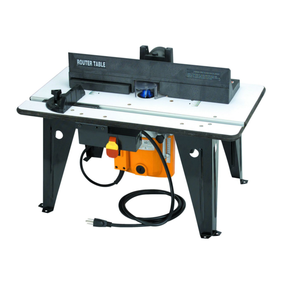
ROUTER TABLE WITH ROUTER
SET UP AND OPERATING INSTRUCTIONS
Visit our website at: http://www.harborfreight.com
Read this material before using this product.
Failure to do so can result in serious injury.
SAVE THIS MANUAL.
Copyright
2006 by Harbor Freight Tools
©
contained herein may be reproduced in any shape or form without the express written consent of
Harbor Freight Tools. Diagrams within this manual may not be drawn proportionally. Due to continuing
improvements, actual product may differ slightly from the product described herein. Tools required for
assembly and service may not be included.
For technical questions or replacement parts, please call 1-800-444-3353.
Manual Revised 11c
Model
95380
. All rights reserved. No portion of this manual or any artwork
®
Advertisement
Table of Contents

Related Manuals for Chicago Electric 95380


Summary of Contents for Chicago Electric 95380
- Page 1 ROUTER TABLE WITH ROUTER Model 95380 SET UP AND OPERATING INSTRUCTIONS Visit our website at: http://www.harborfreight.com Read this material before using this product. Failure to do so can result in serious injury. SAVE THIS MANUAL. Copyright 2006 by Harbor Freight Tools .
-
Page 2: Specifications
SPECIFICATIONS Motor 110 VAC / 60 Hz / 11 A / 1-3/4 HP / 20,000 Maximum RPM Router Type Plunge Router with Brake Router Power Cord SJT 16 AWG x 2C Router Table Power Switch Rocker (ON/OFF) with Safety Key Router Table Power Cord 16 AWG 3C Router Table Power Plug... -
Page 3: Electrical Safety
ELECTRICAL SAFETY Grounded tools must be plugged into an outlet properly installed and grounded in accordance with all codes and ordinances. Never remove the grounding prong or modify the plug in any way. Do not use any adapter plugs. Check with a qualified electrician if you are in doubt as to whether the outlet is properly grounded. - Page 4 Use safety equipment. Always wear ANSI-approved safety impact eye goggles. Dust mask or respirator, and hearing protection must be used for appropriate conditions. TOOL USE AND CARE Do not force the Router. Use the correct tool for your application. The correct tool will do the job better and safer at the rate for which it is designed.
-
Page 5: Specific Safety Rules
SPECIFIC SAFETY RULES Maintain labels and nameplates on the Router and its Table. These carry important information. If unreadable or missing, contact Harbor Freight Tools for a replacement. Avoid unintentional starting. Make sure you are prepared to begin work before turning on the Router. Do not force the Router. - Page 6 Never cut pieces too small to be held securely against the Table’s Fence without leaving enough space for the hand to be a safe distance from the Router Bit (not included). Make sure the Table and surrounding area are clear with the exception of the workpiece to be cut.
- Page 7 examples of these chemicals are: lead from lead-based paints, crystalline silica from bricks and cement or other masonry products, arsenic and chromium from chemically treated lumber. Your risk from these exposures varies, depending on how often you do this type of work. To reduce your exposure to these chemicals: work in a well ventilated area, and work with approved safety equipment, such as those dust masks that are specially designed to filter out microscopic particles.
- Page 8 The tool must be plugged into an appropriate outlet, properly installed and grounded in accordance with all codes and ordinances. The plug and outlet should look like those in the following illustration. (See 3-Prong Plug and Outlet.) ROUTER TABLE POWER CORD USES A 3-PRONG PLUG 3-Prong Plug and Outlet...
- Page 9 ASSEMBLY INSTRUCTIONS Note: For additional information regarding the parts listed in the following pages, refer to the Assembly Diagram on pages 16 and 17. CAUTION! Always make sure the Power Switch (2B) of the Router Table is in its “OFF” position and the unit is unplugged from its electrical outlet prior to performing any assembly procedures.
- Page 10 To Mount The Router Table On A Workbench: CAUTION! Make sure the Router Table is securely attached to a dry, flat, level, sturdy workbench surface capable of supporting the weight of the unit, accessories, and workpieces. At the bottom of each of the four Legs (1B) of the Router Table are two 1/4”...
- Page 11 To Connect A Vacuum Hose To The Dust Port: DUST PORT (1-3/8” OUTSIDE DIAMETER) Figure C The Dust Port of the Router Table is 1-3/8” O.D. (outside diameter) and is located at the rear of the Router Table. Use an automotive hose clamp (not included) to secure an appropriate size vacuum hose (not included) to the Dust Port.
- Page 12 To Install A Router Bit: COLLET CHUCK (5A) WRENCH WARNING! Make sure the Power (10B) Switch of the Router Table is in its “OFF” position and the Router Table is not plugged into an electrical outlet. Fully insert the Router Bit (not included) into the Collet Chuck (5A).
- Page 13 BASIC OPERATING INSTRUCTIONS WARNING! Use safety equipment. Always wear ANSI- approved safety impact eye goggles. Dust mask or respirator, and hearing protection must be used for appropriate conditions. Make sure the Power Switch of the Router Table is in its “OFF” position and the Table is not plugged into an electrical outlet.
-
Page 14: Troubleshooting
TROUBLESHOOTING Problem Possible Solution Router will not run. 1. Make sure the Power Switch of the Router Table is in its “ON” position. 2. Make sure the Power Switch of the Router is in its “ON” position. 3. Make sure the Power Cord of the Router is connected to the Power Table’s Outlet. -
Page 15: Inspection, Maintenance, And Cleaning
INSPECTION, MAINTENANCE, AND CLEANING CAUTION! Always make sure the Power Switch of the Router Table is in its “OFF” position and the Router Table is unplugged from its electrical outlet prior to performing any inspection, maintenance, or cleaning procedures. Before each use, inspect the general condition of the Router and Router Table. -
Page 16: Parts Lists & Assembly Diagrams
PARTS LISTS & ASSEMBLY DIAGRAMS PARTS LIST & ASSEMBLY DIAGRAM A - ROUTER Part Description Qty. Part Description Qty. Machine Screw Insulator Template Guide Tapping Screw Base Assy. Washer Nut Clamp Armature Collet Chuck Stator Assy. Lock Piece Ball Bearing Lock Screw Bearing Bushing Lock Lever... - Page 17 PARTS LIST & ASSEMBLY DIAGRAM B - ROUTER TABLE Part Description Qty. Part Description Qty. Chuck Sleeve (1/2”) Power Switch/Outlets Chuck Sleeve (3/8” Fixed Stand Machine Screw Guiding Groove Spring Lock Washer Work Table Fence Metal Gasket Knob Flat Head Screw Guard Dust Cover Adjustable Fence...
-
Page 18: Limited 90-Day Warranty
LIMITED 90 DAY WARRANTY Harbor Freight Tools Co. makes every effort to assure that its products meet high quality and durability standards, and warrants to the original purchaser that this product is free from defects in materials and workmanship for the period of 90 days from the date of purchase.