
Related Manuals for Hanna Instruments HI 8931


Summary of Contents for Hanna Instruments HI 8931
- Page 1 Instruction Manual HI 8931 • HI 8936 Series HI 943500 Series Conductivity Process Controllers and Transmitters w w w . h a n n a i n s t . c o m...
-
Page 2: Table Of Contents
Dear Customer, Thank you for choosing a HANNA instruments ® product. Please read this instruction manual carefully before using the instru- ment. This manual will provide you with all the necessary information for correct use of the instruments, as well as a precise idea of thier versatility in a wide range of applications. -
Page 3: Preliminary Examination
PRELIMINARY EXAMINATION Four models with different measurement ranges are available to suit Remove the instrument from the packing material and examine it any application needs: carefully to make sure that no damage has occurred during shipping. If there is any noticeable damage, notify your dealer. HI 8931A / HI 943500A / HI 8936A / HI 8936AL •... -
Page 4: Functional Description Hi 8931 & Hi 943500
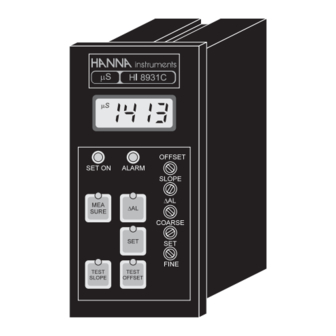
REAR PANEL OF HI 8931 SERIES FUNCTIONAL DESCRIPTION HI 8931 & HI 943500 KEYPAD POWER OUTPUT terminals (+20 V and COM) for connec- MEASURE To read measurements and enable diagnostic tests ΔAL tion to a conductivity transmitter (HI 8936) To display set tolerance of the alarm mA INPUT from a conductivity transmitter To set working point mA OUTPUT terminals for connection to a recorder... - Page 5 REAR PANEL OF HI 943500 SERIES MECHANICAL DIMENSIONS OF HI 8931 AND HI 943500 Front view of the panel-mounted unit 141mm 144mm 5.55" 5.67" 69mm 2.71" 72mm 2.83" These dimensions show the cutout size for the installation. Side view of the panel-mounted unit DIN connector for conductivity probe 0.25/4mm mA OUTPUT terminals for connection to a recorder...
-
Page 6: Functional Description Hi 8936
FUNCTIONAL DESCRIPTION HI 8936 SIDE VIEW OF HI 8936 SERIES HI 8936A HI 8936B HI 8936C HI 8936D HI 8936AL 1. Top cover HI 8936BL 2. Cable glands for wiring HI 8936CL HI 8936DL 1. Back cover 2. Top cover 3. -
Page 7: Conductivity Probes
MECHANICAL DIMENSIONS OF CONDUCTIVITY PROBES HI 8936A, HI8936B, HI 8936C, HI 8936D HI 7635 In-line Conductivity Probe 165mm 6.50" HI 7635 is a one piece, molded conductivity probe with pipe threads (1" NPT) at both ends. 100mm 110mm This allows the probe to attach to an in-line system, and to be used 3.94"... -
Page 8: Specifications Hi 8931 & Hi 943500
SPECIFICATIONS HI 8931 & HI 943500 Range 0.0 to 199.9 mS/cm HI 8931A - HI 943500A HI7638 Tank Conductivity Probe 0.00 to 19.99 mS/cm HI 8931B - HI 943500B 0 to 1999 μS/cm HI 8931C - HI 943500C HI 7638 conductivity probe combines the proven 4-ring potentiometric HI 8931D - HI 943500D 0.0 to 199.9 μS/cm method of measuring conductivity with the platinum sensor and... -
Page 9: Specifications Hi 8936
CONNECTIONS SPECIFICATIONS HI 8936 REAR CONNECTIONS FOR HI 8931 Range HI 8936 A/AL 0.0 to 199.9 mS/cm 0.00 to 19.99 mS/cm HI 8936 B/BL Power Connection Terminals • 0 to 1999 μS/cm HI 8936 C/CL 0.0 to 199.9 μS/cm HI 8936 D/DL 4-screw-terminal-strip for connection Accuracy ±2% of Full Scale... - Page 10 TERMINAL BOARD CONNECTIONS FOR H8936 Set Select • • Remove the 4 screws and the top cover of the HI 8936 conductivity transmitter to obtain access to the terminal board connections. These contacts permit the activation of a Set Contact relay when the measured value is lower (connected terminals) or higher (open termi- nals) than the user's set value.
- Page 11 • Probe Connection The 4-core cable has to be con- The conductivity probe is supplied nected to the transmitter accord- with a 3 m (10'), 6 core cable. ing to the label instructions on the The cable is to be connected to the 4-terminal strip.
- Page 12 REAR CONNECTIONS FOR HI 943500 • Set • Power Connection Terminals Dosing pumps or other control equipment may be connected to the "SET" (Max. 2A, 240 V) terminals. These contacts act only as a 4-screw-terminal-strip for connec- "dry" switch allowing electrical continuity, not as a power supply. tion to a 3-wire power cable ac- cording to the indicated voltage (115 or 230 V).
-
Page 13: Operational Guide
CONDUCTIVITY PROBE CONNECTIONS OPERATIONAL GUIDE The connections for HI 7635 are color coded for easy in- INITIAL PREPARATION & INSTALLATION stallation and are as fol- Material needed: lows: • a 3-wire power cable (to connec the HI 8931 or HI 943500 to the mains) •... - Page 14 • The HI 8936 transmitter may be • It is recommended to install the HI 7635 vertically. This is to wall-mounted at any convenient loca- ensure that trapped air bubbles or turbulent flows cause minimal tion close to the measurement site. interference to the measurement system.
- Page 15 Below Setpoint Control Operation OPERATING INFORMATION Short the "SET SELECT" and "COM" connec- All parameters are set through the front panel keys and trimmers. tors with a jumper wire. The set contact When any key is pressed, the corresponding LED lights up to indicate relay will close if the measured value is that the function is active.
-
Page 16: Calibration Procedure Of Hi 8931 & Hi 8936 With Hi 7635
The alarm contacts of HI 8931 and HI 943500 remain closed during CALIBRATION PROCEDURE OF normal operation. If the measured conductivity level is not within the HI 8931 & HI 8936 WITH HI 7635 tolerance of the set value, the alarm contact will be open. Material needed: TAKING MEASUREMENTS WITH HI 8931 AND HI 943500 •... - Page 17 • Ensure that the HI 7635 conductivity probe is dry. • The reading will be converted to mA by the following formula: mA = K (measured value x 16/2000) + 4 • When the power is on, the ammeter should read "4.0 mA". K = conversion factor depending on the model The HI 8936 transmitter with LCD should display "0".
-
Page 18: Calibration Procedure Of Hi 8931 & Hi 8936 With Hi 7638
• The calibration is now complete and the instrument is ready for CALIBRATION PROCEDURE OF use. All subsequent measurements will be compensated to 25°C HI 8931 & HI 8936 WITH HI 7638 (77°F). • If the instrument will not calibrate, refer to the "Probe Mainte- Material needed: nance and Cleaning"... - Page 19 • Pour at least 8 cm (3¼") of conductiv- • Leave the HI 7638 conductivity probe ity solution into a plastic beaker. in air (dry probe). • When the power is on, the ammeter should read "4.0 mA" or the •...
-
Page 20: Calibration Procedure Of Hi 943500 With Hi 7638
FOR HI 8931 • CALIBRATION PROCEDURE OF When the reading stabilizes, turn the SLOPE trimmer on the front HI 943500 WITH HI 7638 of the HI 8931 until the LCD reading is the same as the calibration solution at 25°C (77°F), i.e. Material needed "80.0 mS"... -
Page 21: Conductivity Versus Temperature Chart
• If the LCD does not show "0", adjust the OFFSET trimmer. CONDUCTIVITY VERSUS TEMPERATURE CHART °C °F HI7030 HI 7031 HI 7033 HI 7034 HI7035 HI7039 (mS/cm) (mS/cm) (mS/cm) (mS/cm) (mS/cm) (mS/cm) 7150 7 7 6 48300 65400 2760 8220 8 9 6 53500... -
Page 22: Diagnostic Tests
DIAGNOSTIC TESTS The HI 8931 and HI 943500 controllers are designed with built-in Test Slope diagnostic functions to enable the user to check and troubleshoot the Press the "TEST SLOPE" key and the display should indicate the instrument. The checks performed are through the front panel keys and following values: can be used to isolate the cause of malfunction. -
Page 23: Installation Examples
Example #3 INSTALLATION EXAMPLES Some typical installation setups are shown in the following examples: Example #1 Example #4 Example #2 Example #5... -
Page 24: Probe Maintenance And Cleaning
ACCESSORIES PROBE MAINTENANCE & CLEANING CONDUCTIVITY CALIBRATION SOLUTIONS The probe can be compensated for normal contamination by a process of re-calibration. It is recommended to remove the probe from its installation regularly for HI 7030L 12880 μS/cm calibration solution, 500 mL maintenance. -
Page 25: Warranty
If the repair is not 2.87" 1" NPT covered by the warranty, you will be notified of the charges incurred. If the instrument is to be returned to HANNA instruments ® , first obtain a Returned Goods Authorization Number from the Customer Service department and then send it with shipment costs prepaid. -
Page 26: Ce Declaration Of Conformity
CE DECLARATION OF CONFORMITY Recommendations for Users Before using these products, make sure that they are entirely suitable for the environment in which they are used. Operation of these instruments in residential area could cause unacceptable interfer- ences to radio and TV equipments, requiring the operator to take all necessary steps to correct interferences. - Page 27 SALES & TECHNICAL SERVICE CONTACTS Australia: Tel. (03) 9769.0666 • Fax (03) 9769.0699 China: Tel. (10) 88570068 • Fax (10) 88570060 Egypt: Tel. & Fax (02) 2758.683 Germany: Tel. (07851) 9129-0 • Fax (07851) 9129-99 Greece: Tel. (210) 823.5192 • Fax (210) 884.0210 Indonesia: Tel.