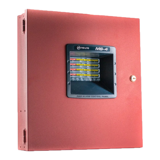
Fire-Lite MS-2 Instruction Manual
Fire alarm control panel
Hide thumbs
Also See for MS-2:
- Owner's manual (21 pages) ,
- User manual (56 pages) ,
- User manual (56 pages)

Related Manuals for Fire-Lite MS-2


Summary of Contents for Fire-Lite MS-2
- Page 1 Fire Alarm Control Panel MS-2 & MS-4 MS-2E & MS-4E Instruction Manual Document 51512 10/18/2011 Rev: P/N 51512:G2 ECN 11-740...
-
Page 2: Fire Alarm System Limitations
Fire Alarm System Limitations While a fire alarm system may lower insurance rates, it is not a substitute for fire insurance! An automatic fire alarm system—typically made up of Heat detectors do not sense particles of combustion and smoke detectors, heat detectors, manual pull stations, audible alarm only when heat on their sensors increases at a predeter- warning devices, and a fire alarm control panel with remote mined rate or reaches a predetermined level. -
Page 3: Installation Precautions
Installation Precautions Adherence to the following will aid in problem-free installation with long-term reliability: WARNING - Several different sources of power can be Like all solid state electronic devices, this system may connected to the fire alarm control panel. Disconnect all operate erratically or can be damaged when subjected to light- sources of power before servicing. - Page 4 Software Downloads In order to supply the latest features and functionality in fire alarm and life safety technology to our customers, we make frequent upgrades to the embedded software in our products. To ensure that you are installing and programming the latest features, we strongly recommend that you download the most current version of software for each product prior to commissioning any system.
-
Page 5: Table Of Contents
Table of Contents Section 1: Product Description ..................... 10 1.1: Product Features ............................10 1.2: Specifications...............................11 1.3: Controls and Indicators..........................12 1.4: Circuits.................................14 1.5: Components ..............................14 1.6: Optional Modules and Accessories ......................14 Section 2: Installation......................17 2.1: Backbox Mounting ............................17 2.2: Operating Power ............................19 2.3: Input Circuits ...............................20 2.4: Output Circuits.............................22 2.4.1: Notification Appliance Circuits......................22... - Page 6 Table of Contents Section 4: Operating Instructions ..................40 4.1: Switch Functions in Normal Mode ......................40 4.1.1: ACK - Acknowledge .........................40 4.1.2: Silence..............................40 4.1.3: Zone Enable/Disable..........................40 4.1.4: Reset/(Lamp Test) ..........................40 4.1.5: Walktest .............................41 4.2: Walktest................................41 4.3: Status LEDs..............................42 4.4: Operation..............................43 4.4.1: Fire Alarm Response .........................44 4.4.2: Fire Alarm Restoral ...........................44 4.4.3: System Supervisory Condition Response ..................44...
- Page 7 It is imperative that the installer understand the requirements of the Authority Having Jurisdiction (AHJ) and be familiar with the standards set forth by the following regulatory agencies: • Underwriters Laboratories Standards • NFPA 72 National Fire Alarm Code Before proceeding, the installer should be familiar with the following documents. NFPA Standards This Fire Alarm Control Panel complies with the following NFPA Standards: NFPA 72 National Fire Alarm Code for Local Fire Alarm Systems and Remote Station...
- Page 8 MS-2 Two Zone Main Circuit Board IDC (4.7 K, ½ watt ELR) (supervised, power-limited) Zone 2 B- Trouble Relay (fail-safe) Zone 2 B+ 2 amps @ 30 VDC Zone 1 B- (nonsupervised) Zone 1 B+ Common NAC (4.7KW, ½ watt ELR) Trouble (Normally Open) 2.5A max.
- Page 9 MS-4 Four Zone Main Circuit Board IDC (4.7 K, ½ watt ELR) TB3 (supervised, power-limited) Zone 4 B- Zone 4 B+ Trouble Relay TB5 (fail-safe) Zone 3 B- 2A @ 30 VDC (nonsupervised) Zone 3 B+ Common Zone 2 B- Trouble (Normally Open) NAC (4.7K, ½...
-
Page 10: Section 1: Product Description
Section 1: Product Description The MS-2 is a two zone FACP (Fire Alarm Control Panel) and the MS-4 is a four zone FACP. The information in this manual refers to both the MS-2 and MS-4 unless otherwise specified. These control panels provide reliable fire signaling protection for small to medium sized commercial, industrial and institutional buildings. -
Page 11: Specifications
Specifications Product Description Zone Enable/Disable (one per zone) • LED Indicators Fire Alarm (one per zone) Supervisory (one per zone) Trouble (one per zone) Maintenance (one per zone) AC Power NAC Disable Zone Disable ... -
Page 12: Controls And Indicators
Product Description Controls and Indicators Initiating Device Circuits - TB3 Alarm Zones 1 & 2 (MS-2 and MS-4) Alarm Zones 3 & 4 (MS-4 only) Power-limited circuitry Operation: All zones Style B (Class B) Normal Operating Voltage: Nominal 20 VDC, Maximum 27 VDC Alarm Current: 15 mA minimum Short Circuit Current: 40 mA maximum Maximum Loop Resistance: 100 ohms... -
Page 13: Led Indicators
Controls and Indicators Product Description • Walktest • Zone Enable/Disable - Zone 1 • Zone Enable/Disable - Zone 2 • Zone Enable/Disable - Zone 3 (MS-4 only) • Zone Enable/Disable - Zone 4 (MS-4 only) LED Indicators • Fire Alarm Zone 1 - red LED •... -
Page 14: Circuits
Product Description Circuits 1.4 Circuits Input Circuits Two input IDCs (Initiating Device Circuits) on the MS-2 and four IDCs on the MS-4 provide Style B (Class B) configurations. All IDCs accept i detectors as well as conventional two-wire smoke detectors, four-wire smoke detectors and normally-open contact devices. Output Circuits •... - Page 15 Optional Modules and Accessories Product Description condition exists. The 4XTMF mounts to the MS-2 main circuit board option module connectors J3 & J5 or the MS-4 main circuit board, occupying one of the two sets of option module connectors J3 &...
- Page 16 Notes MS-2 & MS-4 Series Manual — P/N 51512:G2 10/18/2011...
-
Page 17: Section 2: Installation
Section 2: Installation The cabinet can be surface mounted or semi-flush mounted using the optional Trim Ring P/N: TR-1-R. The door is removable during the installation period by opening and lifting if off the hinges. The cabinet mounts using two key slots at the top of the backbox and two additional 0.250” diameter holes located at the bottom. - Page 18 Installation Backbox Mounting Depth = 2.875” (7.3 cm) Depth = 3.05” (7.75cm) Door = 14.677” (37.28 cm) Door = 15.342” (38.97 cm) Bottom Depth = 4.75” (12.065 cm) Battery Box = 8.5” (21.59 cm) Battery Box = 14.5” (37.384 cm) Figure 2.2 Backbox and Battery Box When using batteries larger than 7 Amp Hour (up to 18 Amp Hour), the BB-17F battery box (or UL-listed equivalent) must be installed.
-
Page 19: Operating Power
Operating Power Installation 2.2 Operating Power WARNING: DISCONNECT POWER SEVERAL DIFFERENT SOURCES OF POWER CAN BE CONNECTED TO THIS PANEL. DISCONNECT ALL SOURCES OF POWER BEFORE SERVICING. THE PANEL AND ASSOCIATED EQUIPMENT MAY BE DAMAGED BY REMOVING AND/OR INSERTING CARDS, MODULES OR INTERCONNECTING CABLES WHILE THIS UNIT IS ENERGIZED. -
Page 20: Input Circuits
Installation Input Circuits 2.3 Input Circuits The MS-2 has two IDCs (Initiating Device Circuits) and the MS-4 has four IDCs. Each circuit is compatible with System Sensor’s i smoke detectors which generate a maintenance signal when the detector becomes dirty and a separate supervisory ‘freeze’ signal when ambient temperature falls below the detector rating. - Page 21 Input Circuits Installation Combination Waterflow/Supervisory Zone A combination Waterflow/Supervisory circuit allows an FACP to distinguish between an Alarm switch (waterflow device) and a Supervisory switch (tamper) installed on the same circuit. The following figure illustrates the wiring of Zone 2 as a Style B (Class B) Waterflow/Supervisory circuit.
-
Page 22: Output Circuits
Installation Output Circuits 2.4 Output Circuits 2.4.1 Notification Appliance Circuits The MS-2 provides one Style Y (Class B) NAC (Notification Appliance Circuit) while the MS-4 provides two Style Y (Class B) NACs. Each circuit is capable of providing a maximum of 2.5 amps of current. -
Page 23: 2: Special Application Dc Power Output Connections
Output Circuits Installation 2.4.2 Special Application DC Power Output Connections Resettable 24 VDC special application power is available on both the MS-2 and MS-4 control panels. Nonresettable 24 VDC special application power is available only on the MS-4. Nonresettable Power (500 mA) -MS-4Only 4-Wire Smoke Detector Power (500 mA) 24 VDC filtered, nonresettable special application power 24 VDC filtered, resettable special application power for... -
Page 24: Power-Limited Wiring Requirements
Installation Power-limited Wiring Requirements 2.5 Power-limited Wiring Requirements Power-limited and nonpower-limited circuit wiring must remain separated in the cabinet. All power-limited circuit wiring must remain at least 0.25” (6.35 mm) away from any nonpower- limited circuit wiring. Furthermore, all power-limited and nonpower-limited circuit wiring must enter and exit the cabinet through different knockouts and/or conduits. -
Page 25: Installation Of Optional Modules
Installation of Optional Modules Installation 2.6 Installation of Optional Modules CAUTION: DISCONNECT POWER REMOVE ALL POWER (AC AND DC) BEFORE INSTALLING OR REMOVING MODULES OR WIRING. 2.6.1 CAC-4 Class A Converter Module (MS-4 only) Installation The CAC-4 Module can be used to convert the four Style B (Class B) Initiating Device Circuits to Style D (Class A) and the two Style Y (Class B) Notification Appliance Circuits to Style Z (Class A). -
Page 26: 2: 4Xtmf, 4Xlmf And 4Xzmf Option Modules
Installation Installation of Optional Modules circuit. Do not wire to the corresponding A+ and A- terminals on the CAC-4 module. Note that Zone 1 IDC on the MS-2 and Zone 2 IDC on the MS-4 can be configured as a combination waterflow/supervisory circuit as illustrated in the following figure. -
Page 27: 4Xtmf Transmitter Module Installation
Installation of Optional Modules Installation The following steps must be followed when installing each of these modules: Remove all power (AC and DC) from the FACP before installing the modules. Cut jumper JP1 (for connectors J3 and J5) and/or JP2 (for connectors J4 and J6) on the main circuit board to allow the control panel to supervise the placement of any installed option module. - Page 28 Installation Installation of Optional Modules Maximum Coil Resistance: 14.6 ohms Maximum allowable wire resistance between panel and trip coil: 3 ohms Municipal Box wiring can leave the building Remote Station Service (NFPA 72 Remote Station Fire Alarm Systems) - Intended for connection to a polarity reversal circuit or a Remote Station receiving unit having compatible ratings: Maximum load for each circuit: 10 mA...
-
Page 29: 4Xzmf Zone Relay Module (Ms-4 Only)
Installation of Optional Modules Installation 4XZMF Zone Relay Module (MS-4 only) The 4XZMF provides four zone alarm, one system alarm and one system trouble Form-C relays. Nonpower-limited and power-limited wiring must have a minimum distance of 0.25”, wire to wire. If this module is used to drive nonpower-limited and power-limited circuits, follow the instructions below: Relay #1 through #4 will activate with... -
Page 30: 4Xlmf Led Interface Module (Ms-4 Only)
Installation Installation of Optional Modules 4XLMF LED Interface Module (MS-4 only) The 4XLMF supports the RZA-4XF Remote Annunciator module. The wiring of this module must follow the requirements as specified in “Power-limited Wiring Requirements” on page 24. Important: The 4XLMF module can only be installed on connectors J3 and J5 of the MS-4 main circuit board. - Page 31 Notes MS-2 & MS-4 Series Manual — P/N 51512:G2 10/18/2011...
-
Page 32: Section 3: Program Options Via Dip Switch
Section 3: Program Options via DIP Switch This section describes the programming options available via DIP switch settings. The FACP can be field programmed using option DIP switches SW1, SW2, and SW3 which are located in the bot- tom right side of the main circuit board. A factory-installed dip switch cover, which prevents acci- dental programming, must first be removed. -
Page 33: Dip Switch Settings
DIP Switch Settings Program Options via DIP Switch 3.1 DIP Switch Settings The following tables list the programmable features for the MS-2 and MS-4. Placing a DIP switch in the ON position will select the feature while placing the DIP switch in the OFF position will deselect the feature. - Page 34 Program Options via DIP Switch DIP Switch Settings Switch Number DIP Switch Number DIP Switch ON Silence Inhibit Auto-silence Temporal Coding Selective Silence (if sync. enabled) Trouble Reminder AC Trouble Delay Autoresettable Supervisory IDC Combination Waterflow/Supervisory Circuit IDC1 Verification IDC1 Supervisory IDC2 Verification IDC2 Supervisory IDC3 Verification...
-
Page 35: 1: Sw1 Dip Switch Settings
DIP Switch Settings Program Options via DIP Switch 3.1.1 SW1 DIP Switch Settings Silence Inhibit Switch 1, placed in the ON position, selects the Silence Inhibit feature. This feature prevents the silencing or resetting of the NACs (Notification Appliance Circuits) for a period of one minute after initiation of an alarm. -
Page 36: Idc Combination Circuit
Program Options via DIP Switch DIP Switch Settings IDC Combination Circuit Switch 8, placed in the ON position, sets IDC #1 on the MS-2 or IDC #2 on the MS-4 as a combi- nation circuit. A combination zone can be used for monitoring supervisory devices such as valve tamper switches and alarm devices such as waterflow switches. -
Page 37: Idc1 Supervisory For Ms-2 Or Idc2 Supervisory For Ms-4
DIP Switch Settings Program Options via DIP Switch IDC1 Supervisory for MS-2 or IDC2 Supervisory for MS-4 Switch 4, placed in the ON position, programs IDC #1 on the MS-2 or IDC #2 on the MS-4 as a Supervisory circuit. A supervisory zone can be used for monitoring supervisory devices such as sprinkler tamper switches. -
Page 38: Nac2 Disable (Ms-4 Only)
Program Options via DIP Switch DIP Switch Settings NAC2 Disable (MS-4 only) Switch 4 only on the MS-4, placed in the ON position, will disable NAC #2, preventing the notifi- cation appliances from activating. This feature may be used during maintenance or while testing the system to prevent building evacuation. - Page 39 Notes MS-2 & MS-4 Series Manual — P/N 51512:G2 10/18/2011...
-
Page 40: Section 4: Operating Instructions
Section 4: Operating Instructions The MS-2 and MS-4 have two modes of operation which are Normal and Walktest modes. Upon initial power-up, the system will be in Normal Mode. This section discusses operation of the control panel in the Normal Mode. 4.1 Switch Functions in Normal Mode 4.1.1 ACK - Acknowledge The Acknowledge button, which is located on the FACP membrane switch panel, silences the... -
Page 41: 5: Walktest
Walktest Operating Instructions 4.1.5 Walktest The Walktest button, which is located on the FACP membrane switch panel, allows a panel walktest to be performed. Pressing and holding the Walktest button for a minimum of two seconds causes the FACP to enter audible walktest. Pressing the Walktest button and then the Silence button and holding both for a minimum of two seconds will cause the panel to enter silent walktest. -
Page 42: Status Leds
Operating Instructions Status LEDs During an audible walktest, if a device remains latched in alarm (such as a Pull Station that is not reset after activation), subsequent testing of devices on the same zone will not trigger the NACs. Be certain to reset or clear each device after testing. Silent Walktest To perform a silent Walktest, press the Walktest button, then press the Alarm Silence button and hold both for a minimum of two seconds. -
Page 43: Operation
Operation Operating Instructions Zone Fire Alarm LED A red LED for each zone that blinks to indicate that an alarm exists on the corresponding zone. It turns on steady when the Acknowledge or Alarm Silence button is pressed. Zone Supervisory LED A yellow LED for each zone that blinks if the zone has been programmed for supervisory and a supervisory condition exists on the corresponding zone. -
Page 44: 1: Fire Alarm Response
Operating Instructions Operation 4.4.1 Fire Alarm Response The control panel will, upon detection of an alarm condition, cause the following: • Latch the alarm condition - requires panel reset to clear alarm condition • Blink the Zone Alarm LED one second On and one second Off •... -
Page 45: 6: Trouble Condition Restoral
Operation Operating Instructions • Pulse the FACP piezo sounder one second On and one second Off • Transfer fail-safe Trouble relay • Additional LEDs will turn on or blink according to the specific trouble NAC Disable LED if NAC has been disabled ... -
Page 46: Section 5: Power Supply Calculations
Section 5: Power Supply Calculations 5.1 Overview This section contains instructions and tables for calculating power supply currents in alarm and standby conditions. This is a four-step process, consisting of the following: Calculating the total amount of AC branch circuit current required to operate the system Calculating the power supply load current for non-fire and fire alarm conditions and calculating the secondary (battery) load Calculating the size of batteries required to support the system if an AC power loss occurs... -
Page 47: Calculating The System Current Draw
Use Table 5.3 on page 48 to calculate current draws as follows: Enter the quantity of devices in all three columns. Enter the current draw where required. Refer to the Fire-Lite Device Compatibility Document for compatible devices and their current draw. -
Page 48: Calculating The Battery Size
Power Supply Calculations Calculating the Battery Size Table 5.3 contains three columns for calculating current draws. For each column, calculate the current and enter the total (in amperes) in the bottom row. When finished, copy the totals from Calculation Column 2 and Calculation Column 3 to Table 5.4 on page 49. Calculation Column 3 Calculation Column 1 Calculation Column 2... -
Page 49: 1: Nfpa Battery Requirements
Calculating the Battery Size Power Supply Calculations Enter the totals from Table 5.3 on page 48, Calculation Columns 2 and 3 where shown. Enter the NFPA Standby and Alarm times (refer to ‘NFPA Requirements’ below). Calculate the ampere hours for Standby and Alarm, then sum the Standby and Alarm ampere hours. -
Page 50: Appendix A: Nfpa Standard-Specific Requirements
Appendix A: NFPA Standard-Specific Requirements The MS-2 and MS-4 have been designed for use in commercial, industrial, and institutional applications and meet the requirements for service under the National Fire Protection Association (NFPA) Standards outlined in this Appendix. The minimum system components required for compliance with the appropriate NFPA standard are listed below: MS-2/MS-4 Control Panel Contains the main control board, cabinet (backbox and door), main power supply transformer, and... -
Page 51: Index
Index Numerics 2 Zone Main Circuit Board 8 backbox 4 Zone Main Circuit Board 9 dimensions 14 411 15 mounting 17 411UD 15 battery 14 4XLMF precautions 19 installation 26 rating 11 see also LED Interface Module 15 battery box 15 see also LED interface module 30 mounting 18 specifications 30... - Page 52 D–L Index short circuit current 12 standby current 12 description 10 wiring 20 device compatibility 10 indicators 12 Digital Alarm Communicator/Transmitter see also LED 11 see also 411 & 411UD 15 Initiating Device Circuit 8 dimensions Class A 25 backbox 14 In-Line resistor dip switch cover 32 IDC combination circuit 21...
- Page 53 Index M–S see also 4XTMF 28 power 12 main circuit board maximum system 12 see also 2 Zone 8 primary 19 see also 4 Zone 9 secondary maintenance 20 see also battery 19 piezo pulse rate 13 see also resettable and nonresettable power maintenance signal see also smoke detector monitoring 10 power supply calculations 46...
- Page 54 T–Z Index option module placement 27 CAC-4 25 supervisory Class A Converter Module 25 piezo pulse rate 13 Class A IDC 26 see also programming supervisory 36 Class A NAC 26 supervisory relay 9 combination waterflow/supervisory 21 contact rating 12 IDC 20 supervisory response 44 NAC 22...
- Page 55 Manufacturer Warranties and Limitation of Liability Manufacturer Warranties. Subject to the limitations set forth herein, Manufacturer warrants that the Products manufactured by it in its Northford, Connecticut facility and sold by it to its authorized Distributors shall be free, under normal use and service, from defects in material and workmanship for a period of thirty six months (36) months from the date of manufacture (effective Jan.
- Page 56 World Headquarters 1 Firelite Place Northford, CT 06472-1653 USA 203-484-7161 fax 203-484-7118 www.firelite.com...