PRESONUS StudioLive 16.0.2 Owner's Manual
Performance and recording digital mixer
Hide thumbs
Also See for StudioLive 16.0.2:
- Owner's manual (291 pages) ,
- Quick start manual (23 pages) ,
- Owner's manual (176 pages)

Related Manuals for PRESONUS StudioLive 16.0.2


Summary of Contents for PRESONUS StudioLive 16.0.2
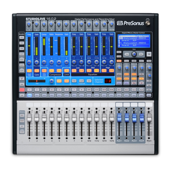
- Page 1 StudioLive 16.0.2 ™ Performance and Recording Digital Mixer Owner’s Manual ® English www.presonus.com...
- Page 2 All PreSonus products in the USA should be serviced at the PreSonus factory in Baton Rouge, Louisiana. The lightning flash with arrowhead symbol within an equilateral triangle is If your product requires a repair, contact support@presonus.com to arrange for a...
-
Page 3: Table Of Contents
Table of Contents Input Channel Strip — 25 Overview — 1 4.3.1 Input Channel Controls — 25 Introduction — 1 Aux and FX Buses — 26 About This Manual — 1 4.4.1 Analog Aux Bus Controls — 26 4.4.2 Internal FX Bus Controls — 27 Summary of StudioLive 16.0.2 Hardware Features —... - Page 4 Stereo Microphone Placement — 60 EQ Frequency Guides — 63 Technical Specifications — 65 StudioLive 16.0.2 Block Diagram — 68 StudioLive 16.0.2 Recall Sheet — 70 Troubleshooting and Warranty — 71 Trouble Shooting — 71 PreSonus Limited Warranty — 72...
-
Page 5: Overview
StudioLive™ 16.0.2 Owner’s Manual Overview Introduction Thank you for purchasing the PreSonus StudioLive™ 16.0.2 Performance and Recording Digital Mixer. PreSonus Audio Electronics has designed the StudioLive utilizing high-grade components to ensure optimum performance that will last a lifetime. Loaded with 12 high-headroom, XMAX™ microphone preamplifiers; a built- in 16x16 FireWire recording and playback engine;... -
Page 6: Summary Of Studiolive 16.0.2 Hardware Features
Summary of StudioLive 16.0.2 Hardware Features Summary of StudioLive 16.0.2 Hardware Features • 24-bit/48 kHz sampling rate • 12 Class A XMAX microphone preamplifiers • 16 line-level inputs • 4 auxiliary buses • High-definition analog-to-digital converters (118 dB dynamic range) •... -
Page 7: What Is In The Box
StudioLive™ 16.0.2 Owner’s Manual What is in the Box Your StudioLive package contains the following: • PreSonus StudioLive 16.0.2 digital recording and performance mixer • 6’ (1.8 m) 6-pin-to-6-pin FireWire 400 cable • 6’ (1.8 m) 6-pin-to-9-pin FireWire 400-to-800 cable •... -
Page 8: Getting Started
Level Setting Procedure Getting Started Before you begin, here are a few general rules of thumb: • Always turn the Main fader and both the Monitor and Phones knobs in the Monitor section down before making connections. • Before plugging or unplugging a microphone while other channels are active, mute the channel to which you are connecting. - Page 9 StudioLive™ 16.0.2 Owner’s Manual Connect the Main outs (TRS or XLR) of your StudioLive to your power amplifier or powered monitors. If you’re using passive speakers, connect them to your power amplifier using speaker cable. Bring down all the faders on your StudioLive to the ∞ setting. Make sure that the Mic/Line knob on Channel 1 is all the way counter-clockwise.
-
Page 10: Level Setting Procedure
Level Setting Procedure Plug your StudioLive into a power outlet and turn it on. If your microphone requires phantom power, engage the 48V button on Channel 1 of your StudioLive. Turn on your amplifier or powered monitors. - Page 11 StudioLive™ 16.0.2 Owner’s Manual Press the Input button in the Meter section. 10. Speak or sing into your microphone at approximately the same volume you expect during the performance. 11. Turn the trim knob on Channel 1 clockwise while watching the first meter in the Fat Channel.
- Page 12 Level Setting Procedure 13. Press the Select button on Channel 1 and raise the Channel 1 fader until it reaches “U” (unity gain). 14. Bring up the Main fader until you can comfortably listen to your microphone through your speakers. 15.
-
Page 13: Hookup
StudioLive™ 16.0.2 Owner’s Manual Hookup Rear-Panel Connections Microphone Inputs. Your StudioLive is equipped with 12 PreSonus XMAX microphone preamplifiers for use with all types of microphones. The XMAX preamplifier has a Class A input buffer, followed by a dual-servo gain stage. This arrangement results in ultra-low noise and wide gain control, allowing you to boost signals without increasing unwanted background noise. - Page 14 Rear-Panel Connections Channels 13/14 and 15/16 have unbalanced RCA connections, in addition to the balanced TRS connections. Like the TRS connections, the right RCA input will not be accessible on the mixer if the channels are not linked. Aux Outputs. The StudioLive is equipped with four auxiliary outputs.
- Page 15 FW400-FW400 and a FW800-FW400 cable have been included for your convenience. You can use the second FireWire port to connect additional FireWire devices (such as external hard drives) to your computer or to daisy-chain a PreSonus FireStudio-family interface for additional recording inputs.
-
Page 16: Typical Live Band Hookup Diagram
Typical Live Band Hookup Diagram Typical Live Band Hookup Diagram Lead Vocal Mic Bass Guitar Keyboard Rhythm Guitar and Amp Drum Set 100 - 240 VAC 50-60Hz Monitors Laptop Front-of-House Speakers MIDI Pedal... -
Page 17: Typical Recording Hookup Diagram
StudioLive™ 16.0.2 Owner’s Manual Typical Recording Hookup Diagram Lead Vocal Mic Rhythm Guitar and Amp Bass Guitar Drum Set 100 - 240 VAC 50-60Hz PreSonus HP60 Headphone Distribution Laptop Reference Monitors MIDI Controller... -
Page 18: Controls
The Fat Channel Controls The Fat Channel The revolutionary Fat Channel is the heart of the StudioLive. The Fat Channel makes dynamics, routing, and panning for every input and output on the StudioLive available at the touch of a Select button. The 12 multipurpose knobs and meters located in the Fat Channel control nearly every adjustment you will need to make on your StudioLive. -
Page 19: Fat Channel Processing Guide
StudioLive™ 16.0.2 Owner’s Manual 4.1.2 Fat Channel Processing Guide The following table provides a quick guide to the processing that is available for each bus in the StudioLive, as well as which inputs and buses are available for recording. For more information on FireWire sends, please see Section 2.5 in the Software Library Reference Manual. -
Page 20: The Fat Channel
The Fat Channel High Pass Filter On/Off. Turns is dependent on the signal the High Pass Filter On/Off for the level after the level crosses the Selected Channel or Output Bus. threshold, whereas a noise gate works independent of a signal’s This button engages and level beyond the threshold. - Page 21 StudioLive™ 16.0.2 Owner’s Manual Compressor Auto Mode Compressor Response. Sets and Button. Enables Automatic Displays the Compressor Response Mode. Response Setting for the Selected Input Channel or Output Bus. When Auto mode is active, the Response control This encoder sets, and the meter becomes inoperative, and a displays, the compressor’s preprogrammed attack and...
-
Page 22: The Fat Channel
The Fat Channel Limiter On/Off. Turns on the Low EQ Gain Control. Sets and Limiter for the Selected Input Displays the Gain Attenuation or Channel or Output Bus. Boost of the Center Frequency. When the limiter is engaged This encoder sets, and the meter the button will illuminate. - Page 23 StudioLive™ 16.0.2 Owner’s Manual Mid EQ Gain Control. Sets and High EQ Frequency Control. Displays the Gain Attenuation or Sets and Displays the Center Boost of the Center Frequency for Frequency of the High EQ. the Mid Band. This encoder sets, and the meter This encoder sets, and the meter displays, the center frequency displays, the gain cut or boost...
-
Page 24: Fat Channel Panning And Stereo Link
The Fat Channel 4.1.4 Fat Channel Panning and Stereo Link The Pan control for each input or output bus is set on the Fat Channel. The LED display shows the Pan setting, and the encoder to the right of the display controls panning for the selected input or output bus. -
Page 25: Copying Fat Channel Settings
4.1.7 Loading Fat Channel Presets The StudioLive comes with a suite of channel-strip presets created by professional users of PreSonus products. These presets provide a great jumping-off point to create a mix quickly and easily. The StudioLive also allows you to create your own library of presets. -
Page 26: Saving Fat Channel Presets
The Fat Channel 4.1.8 Saving Fat Channel Presets If you have created a channel-strip setting in the Fat Channel that you would like to save to the Channel Preset library, press the Fat Channel’s Save button. You will notice that the LCD will display the Channel Preset Save menu. 1. -
Page 27: Channel Presets Library
4.1.9 Channel Presets Library Your StudioLive comes with 50 Fat Channel presets custom designed by professional PreSonus users. These presets can be altered, renamed, and overwritten; however, there are 49 additional empty storage locations for you to build your own custom library of channel-strip settings. -
Page 28: Metering
Metering Metering The StudioLive offers flexible metering at the touch of a button. The 12 meters in the Fat Channel section can monitor: • The input signal for each channel, post-gain and pre-dynamics, pre-EQ, and pre-fader • The gain reduction for each input channel •... -
Page 29: Input Channel Strip
StudioLive™ 16.0.2 Owner’s Manual Input Channel Strip The StudioLive is equipped with all of the standard input controls of an analog mixer. In addition, the StudioLive provides the added flexibility of routing a playback stream from your audio-recording software to the mixer via the FireWire bus, just as if it were an analog input. -
Page 30: Aux And Fx Buses
Aux and FX Buses Aux and FX Buses The aux bus provides outputs to create auxiliary mixes that are separate from the main mix. Your StudioLive is equipped with 6 aux buses: Aux 1 through 4, which have physical output jacks, and EFX A and B, which are the internal effects buses. Aux buses can be used for many applications, the two most common of which are creating monitor mixes and inserting external effects processors into the mix. -
Page 31: Internal Fx Bus Controls
StudioLive™ 16.0.2 Owner’s Manual 4.4.2 Internal FX Bus Controls Internal Effects Bus Select Button. Enables Fat Channel Viewing. As described in section 4.1.1, the Select button routes its effects bus through the Fat Channel, allowing you to add dynamics processing and EQ. Main Assign Button. - Page 32 Aux and FX Buses the pan controls for each of their respective input channels. The meters will display the pan setting of each of the input channels. Use Aux 1 Encoder mode to set the send level of each channel to the aux pair. For more information on stereo linking, please review Section 4.1.4.
-
Page 33: Creating Monitor Mixes
StudioLive™ 16.0.2 Owner’s Manual 4.4.4 Creating Monitor Mixes Creating custom monitor mixes is critical. If musicians can’t hear themselves or their bandmates, their performance will suffer. A monitor mix can be mono or stereo. Most often, an individual live monitor mix is mono and is sent to a floor-wedge or sidefill monitor. -
Page 34: Creating Internal Fx Mixes
Aux and FX Buses 4.4.5 Creating Internal FX Mixes There are at least two main advantages to creating an FX mix, rather than inserting an effect in a channel. First, several channels can be sent to a single processor. In addition to greatly simplifying the number of parameters you have to control, this can create a cohesive sound in your mix. -
Page 35: Multimodes
StudioLive™ 16.0.2 Owner’s Manual MultiModes Each channel and aux on the StudioLive 16.0.2 features a MultiMode button. These buttons allow you to solo or mute a channel or aux, as well as engage the channel FireWire returns. The function of these buttons is determined by the control buttons directly to the left of the row of the MultiMode buttons. -
Page 36: Main Output Bus
Main Output Bus Main Output Bus Main Select Button. Enables Fat Channel Viewing. As previously described in Section 4.1.1, the Select button routes its channel through the Fat Channel, enabling you to add dynamics processing, EQ, panning, etc. Main Fader. Controls the Level of the Main Output. The fader controls the overall level of the main stereo output. -
Page 37: Solo Bus
StudioLive™ 16.0.2 Owner’s Manual Solo Bus The StudioLive features an independent Solo bus. This feature is extremely useful in setting levels for monitor mixes, dialing in dynamics processing on each channel, and fixing issues during a live show without interrupting the main mix. The Solo bus has three modes: AFL (default), PFL, and SIP: •... -
Page 38: Using The Solo Bus For Monitoring
Solo Bus 4.8.2 Using the Solo Bus for Monitoring When mixing live, or when recording multiple musicians at once, it is often necessary to quickly listen in on just one instrument or group. The Solo and Monitor buses can be used together for this purpose. It is important to note that if you wish to monitor with speakers, rather than headphones, it is necessary to connect the speakers to the Control Room outputs on the back of your StudioLive rather than to one of the main output pairs. -
Page 39: Using Solo In Place (Sip) To Set Up A Mix
StudioLive™ 16.0.2 Owner’s Manual 4.8.3 Using Solo in Place (SIP) to Set Up a Mix We started this manual with a quick and easy way to set up the input levels for your StudioLive, ensuring that you have the highest possible input level without clipping your analog-to-digital converters. -
Page 40: Monitor Bus
Monitor Bus Once you are satisfied, bring the fader back down. Kick snare Tom 1 Tom2 OH L Next, press the MultiMode button on the snare-mic channel and repeat steps 4-6. In this way continue with each drum mic, then move on to the other instruments that are connected to your StudioLive. - Page 41 StudioLive™ 16.0.2 Owner’s Manual Monitor Output Level Control. Adjusts the Overall Level of the Monitor Output. This knob adjusts the overall level of the control-room monitor outputs. FireWire Monitor Button. Assigns FireWire Returns 1 and 2 to the Monitor Bus. The FireWire Monitor button patches FireWire returns 1 and 2 to the monitor bus.
-
Page 42: Digital Effects | Master Control
The Digital FX (Effects) Menu Digital Effects | Master Control From the Digital Effects | Master Control section, you can select and change the parameters of the two internal effects processors, and you can store and recall every setting on the StudioLive. Because almost all StudioLive features are controlled from the mixing surface (rather than using menus and submenus), you will mainly use this section... -
Page 43: Creating Fx Presets
FX type can be the foundation for myriad different presets. The StudioLive contains a library of 50 custom reverb and delay presets designed by PreSonus. In addition to these presets, there are 49 available locations for your custom effects library. The factory presets can be altered, renamed, and overwritten. -
Page 44: The Digital Fx (Effects) Menu
The Digital FX (Effects) Menu 8. Turn the Value encoder clockwise or counter-clockwise to change the letter. The StudioLive allows you to customize the name with uppercase and lowercase letters and a selection of numerals and punctuation marks. Press the Tap button to quickly insert a space. -
Page 45: Delay And Its Parameters
StudioLive™ 16.0.2 Owner’s Manual 5.1.3 Delay and its Parameters A delay essentially creates an echo, although you can often use delays to create more complex time-based effects. The source signal is delayed so that it is heard later than it actually occurred. The following parameters are available for the four delay types the StudioLive offers: Time. -
Page 46: Digital Effects Preset Library
The Digital FX (Effects) Menu 5.1.4 Digital Effects Preset Library POS. TYPE NAME POS. TYPE NAME AMBIENCE Natural Cathedral Lively Gymnasium SMALL ROOM Closet Arena Studio A PLATE PlateVerb Shimmer Studio B PlateVerb Thick Bedroom PlateVerb Drums BRIGHT ROOM Kitchen PlateVerb Vox Tile Floors MONO DELAY... -
Page 47: Digital Effects Types
StudioLive™ 16.0.2 Owner’s Manual 5.1.5 Digital Effects Types Your StudioLive contains 13 different effect types from which to create your own custom presets or to redesign the included library of presets. NAME PARAM (L1) PARAM (L2) PARAM (L2) PARAM (L2) PARAM (L2) PARAM (L2) PARAM (L2) -
Page 48: Scenes
Scenes Scenes The StudioLive allows you to create and store a library of Scenes. A Scene is like a snapshot of your mix. It stores each Fat Channel parameter for every input and bus, as well as each fader’s position, the aux and effects mixes, channel mutes and solos, and the input selection (analog input or FireWire playback stream). -
Page 49: Creating A Scene
StudioLive™ 16.0.2 Owner’s Manual 5.2.2 Creating a Scene Creating a Scene requires simply dialing in a mix that you would like to use at a later date and saving it. This has obvious benefits for both studio and live sound. For example, in the studio, saving and recalling a Scene allows you to move to another song or project and come back to the current mix later. - Page 50 Scenes EQ and Dyn: All Fat Channel dynamics processing, filter parameters, and pan position for every channel and bus. Aux Mix: All aux mixes parameters including: • Channel sends to aux mixes • Channel sends to FXA and FXB • Pre1/Pre2 position for each aux and FX bus Faders: All fader positions.
-
Page 51: Fader Locate
StudioLive™ 16.0.2 Owner’s Manual 5.2.4 Fader Locate If you enable fader positions as a part of your Scene recall, the StudioLive will automatically put the meters in Fader Locate mode after you press the Recall button. The Fader Locate button will illuminate, and the meter section of the Fat Channel will display the recalled fader position. -
Page 52: Graphic Equalizer
In general, narrower bandwidth signifies a more precise EQ. But in traditional graphic EQ designs, the center frequency of each band is fixed. PreSonus took a different approach with the StudioLive. The StudioLive graphic EQ is a pool of shelving filters from which coefficients like cutoff frequency, bandwidth, and gain are extracted through a process of curve-fitting. -
Page 53: The Graphic Eq Menu And Controls
StudioLive™ 16.0.2 Owner’s Manual that, when subtracted from the user’s curve, will produce the flattest possible response: 0 dB. The resulting response is then used to find coefficients for the second shelving filter through the same optimization process. Coefficients for all available shelving filters are found through a recursive process. Unlike conventional designs, the frequency and bandwidth of the “bands”... -
Page 54: Saving And Loading Geq Presets
System Menu 5.3.2 Saving and Loading GEQ Presets Like all other parameters on the StudioLive, graphic EQ settings can be stored and recalled. If you have created a graphic EQ setting that you would like to save to the GEQ Preset library, press the Save button in the Fat Channel while that graphic EQ is active. - Page 55 StudioLive™ 16.0.2 Owner’s Manual Aux Send Position Press the Page Down button to access the Aux Pre Position page. By default, all four aux buses are set to Pre 1. This places the send of all 16 channels to the aux bus before the fader, limiter, EQ, and compressor and after the phase-reverse switch, high-pass filter, and noise gate.
-
Page 56: Using Midi Control Mode To Remote-Control Studiolive
Using MIDI Control Mode to Remote-Control StudioLive Lockout Mode Your StudioLive features a Lockout mode that allows you to create a password and lock the controls. This is especially useful in situations where several people will be running sound but only one or two are knowledgeable enough to set up dynamics processing and the like. -
Page 57: Recalling Scenes And Fx Presets Remotely
StudioLive™ 16.0.2 Owner’s Manual 5.5.1 Recalling Scenes and FX Presets Remotely MIDI stands for “Musical Instrument Digital Interface. ” MIDI enables the exchange of performance information (musical notes, program changes, synth parameters, and much more) between electronic musical instruments, effects devices, computers, compatible software applications, and more. -
Page 58: Controlling The Studiolive 16.0.2 With A Behringer Fcb1010
Using MIDI Control Mode to Remote-Control StudioLive In order to set the correct volume for FXA, FXB, and Main output level, your Volume Control Change messages must include values from 0 to 127. FXA and FXB Assign to Mains is a simple toggle message, so it is not value-dependent. The next two sections cover setup instructions for the most popular MIDI footswitch pedals available when this manual was written. - Page 59 Boot your FCB1010 into Global configuration mode by holding the Down pedal while powering on the FCB1010. PreSonus recommends that you do not use Direct Select mode. When your FCB1010 boots up, you will see that the green LED above Direct Select is illuminated.
- Page 60 Using MIDI Control Mode to Remote-Control StudioLive Scene Recall Select Bank 00 by using the Up or Down pedals. Press Pedal 1 to select Preset 1. Press and hold the Down pedal to enter Preset Configuration mode. (You’ll see a flashing green LED.) Press the Up pedal to confirm.
-
Page 61: Controlling The Studiolive
StudioLive™ 16.0.2 Owner’s Manual 5.5.4 Controlling the StudioLive 16.0.2 with a Roland FC-300 Roland FC-300 Patch Mode offers many flexible ways for you to control your StudioLive 16.0.2. Each patch allows you to assign multiple MIDI controls to any of the four control pedals. In this example, we will create a patch that instantly recalls a Scene, and we will assign to other pedals an FXA preset recall and the FXA assignment to the Main bus. - Page 62 Using MIDI Control Mode to Remote-Control StudioLive Creating a New Patch on the Roland FC-300 Now that your StudioLive is set up to communicate with the Roland FC-300, you will need to create a new patch. Remember, you must follow all of the steps in this tutorial to control your StudioLive as previously described.
- Page 63 StudioLive™ 16.0.2 Owner’s Manual FXA Assign/Unassign to Mains Next, we will set CTL Pedal 2 to control the Main assignment (“mute”) for FXA. Press the right Parameter button until the LCD reads “CTL2: Assign. ” The curser should be on the CH# Tx field. Press the Value Down button until the MIDI channel value is “04.
-
Page 64: Resources
Stereo Microphone Placement Resources Stereo Microphone Placement The following are a few recording applications to help you get started with your StudioLive. These are by no means the only ways to record these instruments. Microphone selection and placement is an art. For more information, visit your library or local bookstore, as there are many books and magazines about recording techniques. - Page 65 StudioLive™ 16.0.2 Owner’s Manual Acoustic Guitar Point a small-diaphragm condenser microphone at the 12th fret, approximately 8 inches away. Point a large- diaphragm condenser microphone at the bridge of the guitar, approximately 12 inches from the guitar. Experiment with distances and microphone placement. Another popular method is using an XY microphone placement with two small-diaphragm condenser microphones.
-
Page 66: Stereo Microphone Placement
Stereo Microphone Placement Drum Overheads (XY example) Place two small-diaphragm condenser microphones on an XY stereo-microphone holder (bar). Position the microphones so that each one is at a 45-degree angle, pointed down at the drum kit, approximately 7 or 8 feet above the floor or drum riser. -
Page 67: Eq Frequency Guides
StudioLive™ 16.0.2 Owner’s Manual EQ Frequency Guides Table 1 Instrument What to Cut Why to Cut What to Boost Why to Boost Human Voice 7 kHz Sibilance 8 kHz Big sound 2 kHz Shrill 3 kHz and above Clarity 1 kHz Nasal 200-400 Hz Body... - Page 68 EQ Frequency Guides Table 2 BOOST • harder bass to low • vocal presence frequency • kick & tom attack instruments (kick, • tom, bass) more finger sound on bass • • guitar and snare brighten vocals, • piano and acoustic acoustic guitar, fullness •...
-
Page 69: Technical Specifications
StudioLive™ 16.0.2 Owner’s Manual Technical Specifications Microphone Preamp Type XLR Female, balanced Frequency Response to Direct Output (at unity gain) 20 Hz-40 kHz, ± 0.5 dBu Frequency Response to Main Output (at unity gain) 20 Hz-20 kHz, ± 0.5 dBu Input Impedance 1 kΩ... -
Page 70: Aux Outputs
Technical Specifications Aux Outputs Type ¼” TRS Female, balanced (mono) Rated Output Level +18 dBu Output Impedance 51Ω Monitor Outputs Type 1/4” TRS Female, balanced (stereo pair) Rated Output Level +18 dBu Output Impedance 51Ω System Crosstalk Input to Output (Ref = +4 dBu, 20 Hz-20 kHz, unwtd) -90 dBu Adjacent Channels (Ref = +4 dBu, 20 Hz-20 kHz, unwtd) -87 dBu Noise Gate (Expander) Threshold Range... - Page 71 StudioLive™ 16.0.2 Owner’s Manual Digital Audio ADC Dynamic Range (A-wtd, 48 kHz) 118 dB DAC Dynamic Range (A-wtd, 48 kHz) 118 dB FireWire S400, 400 Mb/s Internal Processing 32-bit, floating point Sampling Rate 44.1, 48 kHz A/D/A Bit Depth 24 bits Reference Level for 0 dBFS -18 dBu Clock...
-
Page 72: Studiolive 16.0.2 Block Diagram
StudioLive 16.0.2 Block Diagram StudioLive 16.0.2 Block Diagram Input Channel Meter FireWire Return Streams 1- 8 Input Channels 1-8 Gain Mic -6 + 65 dB Line -20 +20 dB Phase Gate Equalizer Compressor Limit Main Mix L Mic Input Mic Pre A/D INPUT BUFFER H.P. - Page 73 StudioLive™ 16.0.2 Owner’s Manual Master Bus Dig Out FireWire Send Output Channel Meters 13/14 & 15/16 Gate Compressor Limit Equalizer BALANCE LINE DRIVERS On/Off Left Main Output Right Output Level Attenution 36 - 465Hz .26 - 3.5kHz 1.4k - 18kHz 0 to -40 dB D/A OUTPUT BUFFER Fat Channel...
-
Page 74: Studiolive 16.0.2 Recall Sheet
StudioLive 16.0.2 Recall Sheet StudioLive 16.0.2 Recall Sheet Artist Scene Date TRACK TRIM PRODUCTION NOTES TRACK TRIM PRODUCTION NOTES Instrument Instrument Mic used Mic used Notes Notes Instrument Instrument Mic used Mic used Notes Notes Instrument Instrument Mic used Mic used Notes Notes Instrument... -
Page 75: Troubleshooting And Warranty
Technical support is available via email at techsupport@presonus.com. PreSonus telephone technical support is available to customers in the USA on Monday through Friday from 9 a.m. to 5 p.m. Central Time by calling 1-225- 216-7887. Customers outside of the USA should contact their national or regional distributor for telephone technical support. -
Page 76: Presonus Limited Warranty
PreSonus reserves the right to update any unit returned for repair. PreSonus reserves the right to change or improve the design of the product at any time without prior notice. This warranty does not cover claims for damage due... - Page 77 Note: No product support is available when you call the number above. Refer to your Certificate of Warranty in your Owner’s Manual for PreSonus’ Product Support telephone number. ® Baton Rouge • USA • www.presonus.com...
- Page 78 Consult the dealer or an experienced radio/TV technician for help. CAUTION: Changes or modifications to this device not expressly approved by PreSonus Audio Electronics could void the user’s author- ity to operate the equipment under FCC rules. This apparatus does not exceed the Class A/Class B (whichever is ap-...
- Page 79 Serves 12 © 2012 PreSonus Audio Electronics, Inc. All Rights Reserved. AudioBox, DigiMax, FireStudio, Nimbit, PreSonus, QMix, StudioLive, and XMAX are trademarks or registered trademarks of PreSonus Audio Electronics, Inc. Capture, Impact, Mixverb Presence, RedLightDist, SampleOne, Studio One, and Tricomp are trademarks or registered trademarks of PreSonus Software Ltd.
- Page 80 StudioLive 16.0.2 ™ Performance and Recording Digital Mixer Owner’s Manual 7257 Florida Boulevard • Baton Rouge, ® Louisiana 70806 USA • 1-225-216-7887 Part# 820-SL0002-C www.presonus.com...