Table of Contents
Advertisement
Advertisement
Table of Contents

Related Manuals for Asus M2A-VM HDMI


Summary of Contents for Asus M2A-VM HDMI
- Page 1 M2A-VM HDMI...
- Page 2 Product warranty or service will not be extended if: (1) the product is repaired, modified or altered, unless such repair, modification of alteration is authorized in writing by ASUS; or (2) the serial number of the product is defaced or missing.
-
Page 3: Table Of Contents
Contents Notices......................vi Safety.information..................vii M2A-VM HDMI specifications summary............. x Chapter 1: Product introduction 1.1. Welcome!..................1-2 1.2. Package.contents................1-2 Special features................1-2 1.3.1 Product highlights ............1-2 1.3.2 Innovative ASUS features ..........1-5 Before you proceed.............. - Page 4 Managing and updating your BIOS..........2-2 2.1.1 ASUS Update utility ............2-2 2.1.2 Creating a bootable floppy disk ........2-5 2.1.3 ASUS EZ Flash 2 utility ........... 2-6 2.1.4 Updating the BIOS ............2-7 2.1.5 Saving the current BIOS file ..........2-9 2.1.6 ASUS CrashFree BIOS 3 utility ........
- Page 5 Security ................. 2-35 Tools menu.................. 2-36 2.7.1 ASUS Music Alarm ............2-36 ASUS O.C. Profile ............2-38 2.7.2 2.7.3 ASUS EZ Flash 2 ............2-40 Exit menu..................2-41 Chapter 3: Software support 3.1. Installing.an.operating.system............ 3-2 Support CD/DVD information............3-2 3.2.1 Running the support CD/DVD .........
-
Page 6: Notices
Notices Federal Communications Commission Statement This device complies with Part 15 of the FCC Rules. Operation is subject to the following two conditions: • This device may not cause harmful interference, and • This device must accept any interference received including interference that may cause undesired operation. -
Page 7: Safety.information
Safety information Electrical.safety • To prevent electrical shock hazard, disconnect the power cable from the electrical outlet before relocating the system. • When adding or removing devices to or from the system, ensure that the power cables for the devices are unplugged before the signal cables are connected. If possible, disconnect all power cables from the existing system before you add a device. -
Page 8: About This Guide
Refer to the following sources for additional information and for product and software updates. ASUS.websites The ASUS website provides updated information on ASUS hardware and software products. Refer to the ASUS contact information. Optional documentation Your product package may include optional documentation, such as warranty flyers, that may have been added by your dealer. -
Page 9: Conventions Used In This Guide
Conventions used in this guide To make sure that you perform certain tasks properly, take note of the following symbols used throughout this manual. DANGER/WARNING: Information to prevent injury to yourself when trying to complete a task. CAUTION: Information to prevent damage to the components when trying to complete a task. -
Page 10: M2A-Vm Hdmi Specifications Summary
M2A-VM HDMI specifications summary CPU. Support AMD socket AM2 for AMD Athlon™ 64FX/ Athlon™ 64 X2/Athlon™ 64/Sempron processors AMD64 architecture enables simultaneous 32-bit and 64-bit computing Supports AMD Cool ‘n’ Quiet™ Technology AMD Live!™ Ready Chipset Northbridge: AMD 690G Southbridge: ATI SB600... - Page 11 M2A-VM HDMI specifications summary IEEE1394 TI IEEE 1394a controller supports: - 2 x IEEE 1394a ports PCIe Gigabit LAN Supports up to 10 USB 2.0/1.1 ports Manageability WfM2.0, DMI2.0, WOL by PME, WOR, PXE, WOR by Special features ASUS Q-Fan ASUS C.P.R.
-
Page 13: Chapter 1: Product Introduction
This chapter describes the motherboard features and the new technologies it supports. Product introduction... -
Page 14: Welcome
® The motherboard delivers a host of new features and latest technologies, making it another standout in the long line of ASUS quality motherboards! Before you start installing the motherboard, and hardware devices on it, check the items in your package with the list below. - Page 15 Ray Disc. See pages 1-25 and 1-36 for details. YPbPr TV-out The motherboard supports superior YPbPr TV-out functionality with a higher resolution to 1080i and 720p format, delivering high image quality. See page 1-30, 1-35, and 2-23 for details. ASUS M2A-VM HDMI...
- Page 16 DDR2 memory support ..The motherboard supports DDR2 memory which features data transfer rates of 800MHz/667 MHz/533 MHz to meet the higher bandwidth requirements of the latest 3D graphics, multimedia, and Internet applications. The dual-channel DDR2 architecture doubles the bandwidth of your system memory to boost system performance, eliminating bottlenecks with peak bandwidths of up to 12.8 GB/s.
-
Page 17: Innovative Asus Features
See page 2-34 for details. ASUS.CrashFree.BIOS.3. The ASUS CrashFree BIOS 3 allows users to restore corrupted BIOS data from a USB flash disk containing the BIOS file. This utility saves users the cost and hassle of buying a replacement BIOS chip. See page 2-10 for details. - Page 18 Wake up to the music of your choice instead of the irritating sound of an alarm clock. The ASUS Music Alarm gives you a personal wake-up call with your favorite CD music without having to enter the OS. See page 2-36 for details.
-
Page 19: Before You Proceed
The illustration below shows the location of the onboard LED. SB_PWR M2A-VM HDMI ® Standby Powered M2A-VM HDMI Onboard LED Power ASUS M2A-VM HDMI... -
Page 20: Motherboard.overview
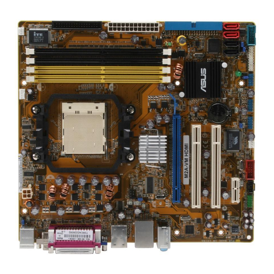
CPU_FAN KBPWR T: Mouse B: Keyboard ATX12V 1394 F_USB34 SPDIF_OUT LAN1_USB12 USBPW1-4 690G Top:Line In Center:Line Out Bottom:Mic In PCIEX16 M2A-VM HDMI RTL8111B PCI1 SB600 ® BIOS PCI2 CR2032 3V Lithium Cell CMOS Power PCIEX1_1 VT6308P ALC883 SB_PWR USBPW5-8 USBPW910... -
Page 21: Placement Direction
1.5.3. Screw.holes Place six (6) screws into the holes indicated by circles to secure the motherboard to the chassis. Do not overtighten the screws! Doing so can damage the motherboard. Place.this.side.towards. the.rear.of.the.chassis M2A-VM HDMI ® ASUS M2A-VM HDMI... -
Page 22: Central.processing.unit.(Cpu)
Installing.the.CPU To install a CPU. Locate the CPU socket on the motherboard. M2A-VM HDMI ® M2A-VM HDMI CPU Socket AM2 Unlock the socket by pressing the lever sideways, then lift it up to a 90°-100° angle. Socket.lever Make sure that the socket lever is lifted up to 90°-100° angle, otherwise the CPU does not fit in completely. - Page 23 Connect the CPU fan cable to the CPU_FAN connector on the motherboard. CPU_FAN M2A-VM HDMI ® M2A-VM HDMI CPU fan connector Do not forget to connect the CPU fan connector! Hardware monitoring errors can occur if you fail to plug this connector. ASUS M2A-VM HDMI...
-
Page 24: Installing The Heatsink And Fan
1.6.2. Installing.the.heatsink.and.fan The AMD Athlon™ 64 X2/Athlon™ 64/Athlon™ FX/Sempron™ processor requires a specially designed heatsink and fan assembly to ensure optimum thermal condition and performance. Make sure that you use only qualified heatsink and fan assembly. Follow these steps to install the CPU heatsink and fan. Place the heatsink on top of the installed CPU, making sure that the heatsink fits properly on the retention module base. - Page 25 Push down the retention bracket lock on the retention mechanism to secure the heatsink and fan to the module base. ASUS M2A-VM HDMI 1-13...
-
Page 26: System.memory
240-pin footprint compared to the 184-pin DDR DIMM. DDR2 DIMMs are notched differently to prevent installation on a DDR DIMM socket. The figure illustrates the location of the DDR2 DIMM sockets: M2A-VM HDMI ® M2A-VM HDMI 240-pin DDR2 DIMM sockets Channel Sockets Channel 1 DIMM_A1 and DIMM_A2... - Page 27 The motherboard can support 8 GB physical memory on the operating system listed below. You may install a maximum of 2 GB DIMMs on each slot. 64-bit Windows XP Professional x64 Edition ® Windows Vista x64 Edition ® ASUS M2A-VM HDMI 1-15...
- Page 28 Qualified Vendors Lists (QVL) DDR2-800 MHz capability Size Vendor .Chip.No. SS/DS Part.No. DIMM. support 512MB KINGSTON K4T51083QC KVR800D2N5/512 • • • 1024MB KINGSTON Heat-Sink Package KHX6400D2LLK2/1GN • • 256MB Qimonda HYB18T512160BF-25F HYS64T32000HU-25F-B • • • 512MB Qimonda HYB18T512800BF25F HYS64T64000HU-25F-B • •...
- Page 29 Dual-channel memory configuration Supports 4 modules inserted into both the yellow slots and the black slots as two pairs of Dual-channel memory configuration Visit the ASUS website for the latest DDR2 DIMM modules for this motherboard. ASUS M2A-VM HDMI 1-17...
-
Page 30: Installing A Dimm
1.7.3. Installing.a.DIMM Make sure to unplug the power supply before adding or removing DIMMs or other system components. Failure to do so may cause severe damage to both the motherboard and the components. Unlock a DIMM socket by pressing DDR2.DIMM.notch the retaining clips outward. -
Page 31: Expansion.slots
Turn on the system and change the necessary BIOS settings, if any. See Chapter 2 for information on BIOS setup. Assign an IRQ to the card. Refer to the tables on the next page. Install the software drivers for the expansion card. ASUS M2A-VM HDMI 1-19... -
Page 32: Interrupt Assignments
Interrupt assignments Standard function High precision event timer Standard 101/102-Key or Microsoft Natural PS/2 keyboard Communications Port (COM1)* Standard floppy disk controller High precision event timer Microsoft ACPI-Compliant System PS/2 Compatible Mouse Numeric data processor Microsoft UAA Bus Driver for High Definition Audio Standard OpenHCD USB Host Controller Standard OpenHCD USB Host Controller Standard OpenHCD USB Host Controller... -
Page 33: Pci Slots
DVI-D out ports on an ATI graphics card. • When installing a PCI Express x16 graphics card, make sure to set the HDMI Support item in the BIOS to [OFF]; otherwise, you will not see the screen display. ASUS M2A-VM HDMI 1-21... -
Page 34: Jumpers
M2A-VM HDMI ® Normal Clear CMOS M2A-VM HDMI Clear RTC RAM (Default) You do not need to clear the RTC when the system hangs due to overclocking. For system failure due to overclocking, use the C.P.R. (CPU Parameter Recall) feature. Shut down and reboot the system so the BIOS can automatically reset parameter settings to default values. -
Page 35: Usb Device Wake-Up
® +5VSB +5VSB (Default) (Default) M2A-VM HDMI USB device wake-up • The USB device wake-up feature requires a power supply that can provide 500mA on the +5VSB lead for each USB port; otherwise, the system will not power up. •... -
Page 36: 1.10 Connectors
1.10 Connectors 1.10.1. Rear.panel.connectors PS/2 mouse port (green). This port is for a PS/2 mouse. Parallel port. This 25-pin port connects a parallel printer, a scanner, or other devices. IEEE 1394a port. This 6-pin IEEE 1394a port provides high-speed connectivity for audio/video devices, storage peripherals, PCs, or portable devices. - Page 37 DVI-D can't be converted to output RGB Signal to CRT and isn't compatible with DVI-I. • To play HD DVD or Blu-Ray Disc, make sure to use an HDCP compliant monitor. 12. PS/2 keyboard port (purple). This port is for a PS/2 keyboard. ASUS M2A-VM HDMI 1-25...
-
Page 38: Internal Connectors
M2A-VM HDMI PIN1 ® M2A-VM HDMI Floppy disk drive connector Chassis intrusion connector (4-1 pin CHASSIS) This connector is for a chassis-mounted intrusion detection sensor or switch. Connect one end of the chassis intrusion sensor or switch cable to this connector. - Page 39 If any device jumper is set as “Cable-Select,” make sure all other device jumpers have the same setting. PRI_IDE NOTE: Orient the red markings (usually zigzag) on the IDE ribbon cable to PIN 1. M2A-VM HDMI ® M2A-VM HDMI IDE connector ASUS M2A-VM HDMI 1-27...
- Page 40 RSATA_RXP2 RSATA_RXP1 RSATA_RXN4 RSATA_RXN3 RSATA_RXN2 RSATA_RXN1 ® M2A-VM HDMI SATA connectors Important.note.on.Serial.ATA Install the Windows XP Service Pack 1 before using Serial ATA. ® • For detailed instructions on how to configure RAID 0, RAID 1, and RAID 10, refer to the RAID manual in the support CD.
- Page 41 SPDIF_OUT M2A-VM HDMI ® M2A-VM HDMI Digital audio connector • The connector of the HDMI module cable integrates the YUV connctor and the SPIDF_OUT connector as the 7-pin YUV/SPIDF_OUT connector.
- Page 42 Never connect a 1394 cable to the USB connectors. Doing so will damage the motherboard! The USB 2.0 module is purchased separately. You can connect the USB cable to ASUS Q-Connector (USB, blue) first, and then install the Q-Connector (USB) to the USB connector onboard. 1-30...
- Page 43 CD-ROM, TV tuner, or MPEG card. (black) M2A-VM HDMI ® M2A-VM HDMI Internal audio connector To activate ASUS Music Alarm: • Connect the analog audio cable from the optical drive to the 4-pin CD-IN connector labeled CD on the motherboard.
-
Page 44: Front Panel Audio Connector
Legacy AC’ 97-compliant pin definition AAFP M2A-VM HDMI ® M2A-VM HDMI Analog front panel connector • We recommend that you connect a high-definition front panel audio module to this connector to avail of the motherboard high-definition audio capability. • If you want to connect a high-definition front panel audio module to this connector, make sure that the Front.Panel.Type item in the BIOS is set to... -
Page 45: Atx Power Connectors
PSON# Ground Ground +3 Volts -12 Volts M2A-VM HDMI ATX power connectors +3 Volts +3 Volts • We recommend that you use an ATX 12 V Specification 2.0-compliant power supply unit (PSU) with a minimum of 300 W power rating. This PSU type has 24-pin and 4-pin power plugs. -
Page 46: System Panel Connector
IDE_LED ® PWRSW Requires an ATX power supply. M2A-VM HDMI System panel connector • System power LED This 2-pin connector is for the system power LED. Connect the chassis power LED cable to this connector. The system power LED lights up when you turn on the system power, and blinks when the system is in sleep mode. - Page 47 This table indicates two corresponding displays when you connect two monitors on any two of the following ports. Onboard.VGA.ports. HDMI module ports DVI. HDMI TV (S-Video/ Video/YPbPr) • • • • • • • • • • ASUS M2A-VM HDMI 1-35...
- Page 48 Playback of HD DVD and Blu-Ray Discs The speed and bandwidth of the CPU/Memory, DVD player, and drivers will affect the playback quality. Following is a configuration example for your reference. Using the CPU/Memory of higher speed and bandwidth with the higher-version DVD player and drivers will upgrade the playback quality.
- Page 49 ASUS.Q-Connector.(system.panel) You can use the ASUS Q-Connector to connect/disconnect chassis front panel cables in a few steps. Refer to the instructions below to install the ASUS Q-Connector. Connect the front panel cables to the ASUS Q-Connector. Refer to the labels on the Q-Connector...
- Page 50 1-38 Chapter 1: Product introduction...
-
Page 51: Chapter 2: Bios Setup
This chapter tells how to change the system settings through the BIOS Setup menus. Detailed descriptions of the BIOS parameters are also provided. BIOS setup... -
Page 52: Managing And Updating Your Bios
ASUS Update (Updates the BIOS in Windows environment.) ® ASUS EZ Flash 2 (Updates the BIOS using a floppy disk/ USB flash disk or the motherboard support CD/DVD.) Award BIOS Flash Utility (Updates the BIOS in DOS mode using a bootable floppy disk.) - Page 53 To update the BIOS through the Internet: Launch the ASUS Update utility from the Windows desktop by clicking Start ® > Programs > ASUS > ASUSUpdate > ASUSUpdate. The ASUS Update main window appears. Select Update BIOS from the Select the ASUS FTP site nearest...
- Page 54 To update the BIOS through a BIOS file: Launch the ASUS Update utility from the Windows desktop by clicking Start ® > Programs > ASUS > ASUSUpdate > ASUSUpdate. The ASUS Update main window appears. Select Update BIOS from a file option from the drop-down menu, then click Next.
-
Page 55: Creating A Bootable Floppy Disk
Click File from the menu, then select Format..A.Format 3 1/2 Floppy Disk window appears. XP users: Select Create an MS-DOS startup disk from the e. Windows ® format options field, then click Start. Copy the original or the latest motherboard BIOS file to the bootable floppy disk. ASUS M2A-VM HDMI... -
Page 56: Asus Ez Flash 2 Utility
2.1.3 ASUS EZ Flash 2 utility The ASUS EZ Flash 2 feature allows you to update the BIOS without having to go through the long process of booting from a floppy disk and using a DOS-based utility. The EZ Flash 2 utility is built-in the BIOS chip so it is accessible by pressing <Alt>... -
Page 57: Updating The Bios
Flash Utility. Follow these instructions to update the BIOS using this utility. 1. Download the latest BIOS file from the ASUS web site. Rename the file to M2A-VM.BIN and save it to a floppy disk, CD ROM or a USB flash disk in FAT 16/12 format. - Page 58 Press <N> when the utility prompts you to save the current BIOS file. The following screen appears. The utility verifies the BIOS AwardBIOS Flash Utility for ASUS V1.17 file in the floppy disk, CD (C) Phoenix Technologies Ltd. All Rights Reserved...
-
Page 59: Saving The Current Bios File
To save the current BIOS file using the AwardBIOS Flash Utility: Follow steps 1 to 6 of the AwardBIOS Flash Utility for ASUS V1.17 previous section. (C) Phoenix Technologies Ltd. All Rights Reserved Press <Y> when the utility... -
Page 60: Asus Crashfree Bios 3 Utility
2.1.6 ASUS CrashFree BIOS 3 utility The ASUS CrashFree BIOS 3 is an auto recovery tool that allows you to restore the BIOS file when it fails or gets corrupted during the updating process. You can update a corrupted BIOS file using the motherboard support CD/DVD, the floppy disk, or the USB flash disk that contains the updated BIOS file. -
Page 61: Bios Setup Program
The BIOS setup screens shown in this section are for reference purposes only, and may not exactly match what you see on your screen. • Visit the ASUS website (www.asus.com) to download the latest BIOS file for this motherboard. ASUS M2A-VM HDMI... -
Page 62: Bios Menu Screen
The BIOS setup screens shown in this chapter are for reference purposes only, and may not exactly match what you see on your screen. • Visit the ASUS website (www.asus.com) to download the latest BIOS information. 2-12 Chapter 2: BIOS setup... -
Page 63: Legend Bar
A configurable field is enclosed in brackets, and is highlighted when selected. To change the value of a field, select it then press <Enter> to display a list of options. Refer to “2.2.7 Pop-up window.” ASUS M2A-VM HDMI 2-13... -
Page 64: Pop-Up Window
[1.44M, 3.5 in. Specifies the capacity and physical size of diskette Primary IDE Master [ST321122A] Legacy Diskette A: drive A. Primary IDE Slave [ASUS CDS520/A] SATA1 [None] Disabled ..[ ] SATA2 [None] 720K , 3.5 in..[ ]... -
Page 65: Main Menu
2.3.2 System Date [Day xx/xx/xxxx] Allows you to set the system date. 2.3.3 Legacy Diskette A [1.44M, 3.5 in.] Sets the type of floppy drive installed. Configuration options: [Disabled] [720K , 3.5 in.] [1.44M, 3.5 in.] ASUS M2A-VM HDMI 2-15... -
Page 66: Primary Ide Master/Slave
2.3.4 Primary IDE Master/Slave While entering Setup, the BIOS automatically detects the presence of IDE devices. There is a separate sub-menu for each IDE device. Select a device item then press <Enter> to display the IDE device information. Phoenix-Award BIOS CMOS Setup Utility Main Primary IDE Master Select Menu... - Page 67 FDISK, to partition and format new IDE hard disk drives. This is necessary so that you can write or read data from the hard disk. Make sure to set the partition of the Primary IDE hard disk drives to active. ASUS M2A-VM HDMI 2-17...
-
Page 68: Sata 1-4
2.3.5. SATA.1-4 While entering Setup, the BIOS automatically detects the presence of Serial ATA devices. There is a separate sub-menu for each SATA device. Select a device item then press <Enter> to display the SATA device information. Phoenix-Award BIOS CMOS Setup Utility Main SATA 1 Select Menu... -
Page 69: Hdd Smart Monitoring
Allows you to enable or disable the HDD Self-Monitoring Analysis and Reporting Technology (SMART) feature. Configuration options: [Disabled] [Enabled] 2.3.7. Installed.Memory.[xxx.MB] Shows the size of installed memory. 2.3.8 Usable Memory [XXX MB] Shows the size of usable memory. ASUS M2A-VM HDMI 2-19... -
Page 70: Advanced Menu
Advanced menu The Advanced menu items allow you to change the settings for the CPU and other system devices. Take caution when changing the settings of the Advanced menu items. Incorrect field values can cause the system to malfunction. Phoenix-Award BIOS CMOS Setup Utility Main Advanced Power... -
Page 71: Cpu Configuration
[Disabled] AMD Cool’n’Quiet Function [Auto] AMD.Live!.[Disabled] Enables or disables the AMD Live! technology. Configuration options: [Disabled] [Enabled] AMD Cool ‘n’ Quiet Function [Disabled] Enables or disables the AMD Cool ‘n’ Quiet technology. Configuration options: [Auto] [Disabled] ASUS M2A-VM HDMI 2-21... -
Page 72: Chipset
2.4.3. Chipset Phoenix-Award BIOS CMOS Setup Utility Advanced Chipset Select Menu Item Specific Help DRAM Configuration LDT & PCI Bus Control UMA Frame Buffer Size [64MB] DRAM timing and control Current UMA Size 64 MB TV Standard [NTSC] Surroundview Disabled HDMI Support [OFF] HDMI Audio... - Page 73 Make sure to set the HDMI Support item to [ON] and the HDMI Audio item to [Enabled] after installing the HDMI module into the onboard PCI Express x16 slot. Spread Spectrum [Auto] Allows you to disable or set to Auto the clock generator spread spectrum. Configuration options: [Disabled] [Auto ASUS M2A-VM HDMI 2-23...
-
Page 74: Pcipnp
2.4.3. PCIPnP Phoenix-Award BIOS CMOS Setup Utility Advanced PCIPnP Select Menu Plug & Play O/S [No] Item Specific Help Resources Controlled By [Auto] Select Yes if you are using IRQ Resources a Plug and Play capable PCI Latency Timer(CLK) [64] operating system Select No if you need the BIOS to... -
Page 75: Onboard Device Configuration
Allows you to enable or disable the onchip IDE channel 0 controller . Configuration options: [Disabled] [Enabled] IDE Prefetch Mode [Disabled] Allows you to enable or disable the IDE PIO read prefetch mode. Configuration options: [Disabled] [Enabled] ASUS M2A-VM HDMI 2-25... - Page 76 South OnChip PCI Device Phoenix-Award BIOS CMOS Setup Utility Advanced South OnChip PCI Device Select Menu Onboard SATA Controller [Enabled] Item Specific Help Onboard SATA Type [RAID Controller] Onboard SATA Controller [Enabled] Allows you to enable or disable the onboard Serial ATA controller. Configuration options: [Disabled] [Enabled] Onboard SATA Type [IDE Controller] Allows you to select the onboard Serial ATA type.
-
Page 77: Usb Configuration
Allows you to enable or disable the onchip USB controller. Configuration options: [Disabled] [Enabled] USB Legacy Support [Enabled] Allows you to enable or disable support for USB devices on legacy operating systems (OS). Configuration options: [Disabled] [Enabled] ASUS M2A-VM HDMI 2-27... -
Page 78: Power Menu
Power menu The Power menu items allow you to change the settings for the Advanced Configuration and Power Interface (ACPI) and the Advanced Power Management (APM). Select an item then press <Enter> to display the configuration options. Phoenix-Award BIOS CMOS Setup Utility Main Advanced Power... - Page 79 Allows you to enable or disable RTC to generate a wake event. When this item is set to Enabled, the items Date of Month Alarm and Time (hh:mm:ss) Alarm items become user-configurable with set values. Configuration options: [Disabled] [Enabled] ASUS M2A-VM HDMI 2-29...
-
Page 80: Hardware Monitor
Date of Month Alarm [xx] To set the date of alarm, highlight this item and press <Enter> to display the Date of Month Alarm pop-up menu. Key-in a value within the specified range then press <Enter>. Configuration options: [Min=0] [Max=31] Alarm Time (hh:mm) [xx:xx:xx] To set the time of alarm: 1. - Page 81 Chassis, and chip fan speeds in rotations per minute (RPM). If any of the fans is not connected to the motherboard, the field shows 0. These items are not user- configurable. CPU.Fan.Speed.warning.[800.RPM]. Sets the CPU fan speed warning feature. Configuration options: [Disabled] [800RPM] [1200RPM] [1600RPM] ASUS M2A-VM HDMI 2-31...
-
Page 82: Boot Menu
Boot menu The Boot menu items allow you to change the system boot options. Select an item then press <Enter> to display the sub-menu. Phoenix-Award BIOS CMOS Setup Utility Main Advanced Power Boot Tools Exit Select Menu Boot Device Priority Removable Drives Hard Disk Drives Item Specific Help... -
Page 83: Hard Disk Drives
Refer to section “1.10.2 Internal connectors” for setting details. Configuration options: [Disabled] [Enabled] Quick Boot [Enabled] Allows you to enable or disable the system quick boot feature. When Enabled, the system skips certain tests while booting. Configuration options: [Disabled] [Enabled] ASUS M2A-VM HDMI 2-33... - Page 84 Allows you to enable or disable the full screen logo display feature. Configuration options: [Disabled] [Enabled] Make sure that the above item is set to [Enabled] if you want to use the ASUS MyLogo2™ feature. Halt On [All, But Keyboard] Allows you to error report type.
-
Page 85: Security
This field requires you to enter the password before entering the BIOS setup or the system. Select [Setup] to require the password before entering the BIOS Setup. Select [System] to require the password before entering the system. Configuration options: [Setup] [System] ASUS M2A-VM HDMI 2-35... -
Page 86: Tools Menu
→←: Select Menu Enter: Select SubMenu F10: Save and Exit ASUS Music Alarm [Disabled] Allows you to enable or disable the ASUS Music Alarm function. Configuration options: [Disabled] [Enabled] The succeeding items become user-configurable when you enable the ASUS Music Alarm. - Page 87 Configuration options: [01] ~ [32] • Only the IDE ATAPI devices from Southbridge can support this function. • The system needs standby power, so ensure that the power cord is plugged. • ASUS Music Alarm only supports audio CDs. ASUS M2A-VM HDMI 2-37...
-
Page 88: Asus O.c. Profile
2.7.2 ASUS O.C. Profile Phoenix-Award BIOS CMOS Setup Utility Tools Select Menu ASUS O.C. Profile Load BIOS Profile Item Specific Help Save BIOS Profile Press [Enter] to Set. Load BIOS Profile Phoenix-Award BIOS CMOS Setup Utility Tools Select Menu Load BIOS Profile... -
Page 89: Save Bios Profile
5. Key in the file name. Then press <Enter>. 6. A pop-up message will inform you when the loading process finishes. ASUSTek O.C. Profile Utility B318 Current CMOS Update CMOS BOARD: Unknown BOARD: M2A-VM HDMI VER: Unknown VER: 0104 DATE: Unknown DATE: 12/12/2006 PATH: A WIN98SE <DIR>... -
Page 90: Asus Ez Flash 2
2.7.3. ASUS.EZ.Flash.2 Allows you to run ASUS EZ Flash 2. When you press <Enter>, a confirmation message appears. Use the left/right arrow key to select between [Yes] or [No], then press <Enter> to confirm your choice. Please see page 2-6, section 2.1.3 for details. -
Page 91: Exit Menu
Discard.Changes This option allows you to discard the selections you made and restore the previously saved values. After selecting this option, a confirmation appears. Select YES to discard any changes and load the previously saved values. ASUS M2A-VM HDMI 2-41... - Page 92 2-42 Chapter 2: BIOS setup...
-
Page 93: Chapter 3: Software Support
This chapter describes the contents of the support CD that comes with the motherboard package. Software support... -
Page 94: Installing.an.operating.system
The contents of the support CD/DVD are subject to change at any time without notice. Visit the ASUS website(www.asus.com) for updates. 3.2.1 Running the support CD/DVD Place the support CD/DVD to the optical drive. -
Page 95: Drivers Menu
The drivers menu shows the available device drivers if the system detects installed devices. Install the necessary drivers to activate the devices. ASUS InstAll - Drivers Installation Wizard Launches the ASUS InstallAll driver installation wizard. AMD Cool ‘n’ Quiet Driver Installs the AMD Cool ‘n’ Quiet driver. -
Page 96: Utilities Menu
ASUS Music Alarm The ASUS Music Alarm is an audio alarm clock that uses your favorite CD music to give you a personal wake-up call. The screen display and utilities option may not be the same for different operating system versions. -
Page 97: Make Disk Menu
The Manual menu contains a list of supplementary user manuals. Click an item to open the folder of the user manual. Most user manual files are in Portable Document Format (PDF). Install the Adobe Acrobat Reader from the Utilities menu before opening a user manual ® ® file. ASUS M2A-VM HDMI... -
Page 98: Asus Contact Information
3.2.6. ASUS.Contact.information Click the Contact tab to display the ASUS contact information. You can also find this information on the inside front cover of this user guide. 3.2.7. Other.information The icons on the top right corner of the screen give additional information on the motherboard and the contents of the support CD/DVD. -
Page 99: Technical Support Form
Browse this CD/DVD Displays the support CD/DVD contents in graphical format. Technical support Form Displays the ASUS Technical Support Request Form that you have to fill out when requesting technical support. Filelist Displays the contents of the support CD/DVD and a brief description of each in text format. - Page 100 Chapter 3: Software support...