Table of Contents
Advertisement
Advertisement
Table of Contents

Related Manuals for Asus M2A74-AM SE


Summary of Contents for Asus M2A74-AM SE
- Page 1 M2A74-AM SE...
- Page 2 Product warranty or service will not be extended if: (1) the product is repaired, modified or altered, unless such repair, modification of alteration is authorized in writing by ASUS; or (2) the serial number of the product is defaced or missing.
-
Page 3: Table Of Contents
Contents Notices ......................v Safety information ..................vi About this guide ..................vi M2A74-AM SE specifications summary ..........viii Chapter 1: Product introduction Before you proceed ..............1-1 Motherboard overview ..............1-2 1.2.1 Motherboard layout ............1-2 1.2.2 Layout contents ............... 1-2 Central Processing Unit (CPU) ........... - Page 4 Boot menu .................. 2-13 2.6.1 Boot Device Priority ............2-14 2.6.2 Boot Settings Configuration .......... 2-14 2.6.3 Security ................. 2-14 Tools menu ................. 2-16 2.7.1 ASUS EZ Flash 2 ............2-16 2.7.2 AI NET 2................ 2-16 Exit menu ..................2-16...
-
Page 5: Notices
Notices Federal Communications Commission Statement This device complies with Part 15 of the FCC Rules. Operation is subject to the following two conditions: • This device may not cause harmful interference, and • This device must accept any interference received including interference that may cause undesired operation. -
Page 6: Safety Information
Safety information Electrical safety • To prevent electric shock hazard, disconnect the power cable from the electric outlet before relocating the system. • When adding or removing devices to or from the system, ensure that the power cables for the devices are unplugged before the signal cables are connected. If possible, disconnect all power cables from the existing system before you add a device. -
Page 7: Conventions Used In This Guide
Refer to the following sources for additional information and for product and software updates. ASUS websites The ASUS website provides updated information on ASUS hardware and software products. Optional documentation Your product package may include optional documentation, such as warranty flyers, that may have been added by your dealer. -
Page 8: M2A74-Am Se Specifications Summary
* DDR2 1066 is supported by AM3/AM2+ CPU only. Refer to www.asus.com for the AM3/AM2+ CPU models. ** Refer to www.asus.com for the latest Memory QVL (Qualified Vendors List). *** When you install a total memory of 4GB or more,... - Page 9 M2A74-AM SE specifications summary PCIe 10/100 LAN ASUS overclocking SFS (Stepless Frequency Selection) from 200MHz to features 550MHz at 1MHz increment Adjustable DRAM voltage ASUS C.P.R. (CPU Parameter Recall) Other features ASUS Q-FAN ASUS CrashFree BIOS 3 ASUS EZ Flash 2...
-
Page 10: Chapter 1: Product Introduction
Chapter 1 Product introduction Thank you for buying an ASUS M2A74-AM SE motherboard! ® Before you start installing the motherboard, and hardware devices on it, check the items in your motherboard package. Refer to page ix for the list of accessories. -
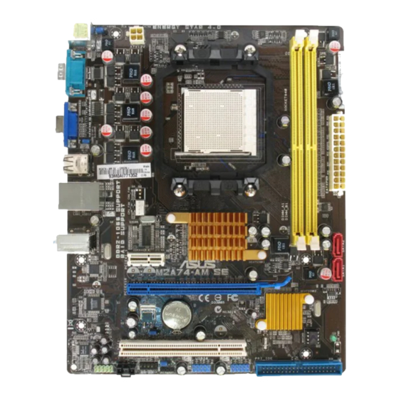
Page 11: Motherboard Overview
Serial ATA connectors (7-pin SATA1, SATA2) 1-10 14. Front panel audio connector (10-1 pin AAFP) 1-14 CPU fan connector (4-pin CPU_FAN) 1-12 15. Clear RTC RAM (3-pin CLRTC) Standby power LED (SB_PWR) 16. PCIe x16/PCIe x1/PCI slots ASUS M2A74-AM SE... -
Page 12: Central Processing Unit (Cpu)
Central Processing Unit (CPU) The motherboard comes with a CPU socket designed for AMD AM3 Phenom™ II / ® Athlon™ X4 / Athlon™ X3 / Athlon™ X2 processors and AM2+ / AM2 Phenom™ X4 / Phenom™ X3 / Athlon™ X2 / Athlon™ / Sempron™ processors. The CPU socket is not compatible with AMD Opteron™... - Page 13 M2A74-AM SE Motherboard Qualified Vendors List (QVL) DDR2-1066MHz capability DIMM socket support Size Vendor Part No. SS/DS Chip No. Chip Brand 512MB Kingston KHX8500D2/512 Heat-Sink Package Kingston · · 512MB Kingston KVR1066D2N7/512 E5108AJBG-1J-E Elpida · · 512MB Kingston KHX8500D2K2/1GN Heat-Sink Package Kingston ·...
- Page 14 DDR2-800MHz capability DIMM socket support Chip Size Vendor Part No. Chip No. Brand Apacer 78.01GA0.9K5 AM4B5808CQJS8E0749D Apacer · · Apacer 78.A1GA0.9K4 AM4B5808CQJS8E0740E Apacer · · 512MB Transcend TS64MLQ64V8J512MB 7HD22 D9GMH Micron · · Transcend 505649-1993 7HD22D9GMH Micron · · Transcend TS128MLQ64V8J TQ123PJF8F0801 Transcend...
-
Page 15: Expansion Slots
• B*: Supports one pair of modules inserted into both the yellow slots as one pair of dual-channel memory configuration. Visit the ASUS website at www.asus.com for the latest QVL. Expansion slots In the future, you may need to install expansion cards. The following sub-sections describe the slots and the expansion cards that they support. -
Page 16: Configuring An Expansion Card
1.5.2 Configuring an expansion card After installing the expansion card, configure it by adjusting the software settings. Turn on the system and change the necessary BIOS settings, if any. See Chapter 2 for information on BIOS setup. Assign an IRQ to the card. Install the software drivers for the expansion card. - Page 17 • The USB device wake-up feature requires a power supply that can provide 500mA on the +5VSB lead for each USB port; otherwise, the system would not power up. • The total current consumed must NOT exceed the power supply capability (+5VSB) whether under normal condition or in sleep mode. ASUS M2A74-AM SE...
-
Page 18: Connectors
Connectors 1.7.1 Rear panel ports PS/2 Mouse port. This port is for a PS/2 mouse. LAN (RJ-45) port. This port allows 10/100 PCIe connection to a Local Area Network (LAN) through a network hub. LAN port LED indications (Orange) (Green) LED (Orange) LED (Green) Status... -
Page 19: Internal Connectors
XP Service Pack 1 before using Serial ATA. ® Optical drive audio in connector (4-pin CD) This connector allows you to receive stereo audio input from sound sources such as a CD-ROM, TV tuner, or MPEG card. ASUS M2A74-AM SE 1-10... - Page 20 IDE connector (40-1 pin PRI_IDE) The onboard IDE connector is for an Ultra DMA 133/100/66 signal cable. There are three connectors on each Ultra DMA 133/100/66 signal cable: blue, black, and gray. Connect the blue connector to the motherboard’s IDE connector, then select one of the following modes to configure your devices.
- Page 21 DO NOT forget to connect the CPU fan cable to the CPU fan connector. Insufficient air flow inside the system may damage the motherboard components. It is not a jumper! DO NOT place a jumper cap on the CPU fan connector. Only the CPU fan supports the ASUS Q-Fan feature. ASUS M2A74-AM SE 1-12...
- Page 22 The system may become unstable or may not boot up if the power is inadequate. • If you are uncertain about the minimum power supply requirement for your system, refer to the Recommended Power Supply Wattage Calculator at http://support.asus. com/PowerSupplyCalculator/PSCalculator.aspx?SLanguage=en-us for details. Speaker connector (4- pin SPEAKER) This 4-pin connector is for the chassis-mounted system warning speaker.
-
Page 23: System Panel Connector
Front Panel Select item in the BIOS is set to [HD Audio]. If you want to connect an AC97 front panel audio module to this connector, set the item to [AC97]. See page 2-11 for details. ASUS M2A74-AM SE 1-14... -
Page 24: Software Support
Autorun function is enabled on your computer. The contents of the Support DVD are subject to change at any time without notice. Visit the ASUS website at www.asus.com for updates. Click an icon to display Support DVD/... -
Page 25: Chapter 2: Bios Information
BIOS in the future. Copy the original motherboard BIOS using the ASUS Update utility. 2.1.1 ASUS Update utility The ASUS Update is a utility that allows you to manage, save, and update the motherboard BIOS in Windows environment. ®... -
Page 26: Asus Ez Flash 2 Utility
When the correct BIOS file is found, EZ Flash 2 performs the BIOS updating process and automatically reboots the system when done. • Only a USB flash disk with FAT 32/16 format and single partition supports the ASUS EZ Flash 2 utility. -
Page 27: Asus Crashfree Bios 3 Utility
2.1.3 ASUS CrashFree BIOS 3 utility The ASUS CrashFree BIOS 3 is an auto recovery tool that allows you to restore the BIOS file when it fails or gets corrupted during the updating process. You can update a corrupted BIOS file using the motherboard Support DVD or a USB flash disk that contains the updated BIOS file. -
Page 28: Bios Setup Program
• The BIOS setup screens in this section are for reference only. They may not exactly match what you see on your screen. • Visit the ASUS website at www.asus.com to download the latest BIOS file for this motherboard. Main menu When you enter the BIOS Setup program, the Main menu screen appears, giving you an overview of the basic system information. -
Page 29: Primary Ide Master/Slave
2.3.3 Primary IDE Master/Slave While entering Setup, the BIOS automatically detects the presence of IDE devices. There is a separate submenu for each IDE device. Select a device item then press <Enter> to display the IDE device information. The BIOS automatically detects the values opposite the dimmed items (Device, Vendor, Size, LBA Mode, Block Mode, PIO Mode, Async DMA, Ultra DMA, and SMART monitoring). -
Page 30: Sata Configuration
This menu gives you an overview of the general system specifications. The BIOS automatically detects the items in this menu. BIOS Information Displays the auto-detected BIOS information Processor Displays the auto-detected CPU specification System Memory Displays the auto-detected system memory ASUS M2A74-AM SE... -
Page 31: Advanced Menu
Advanced menu The Advanced menu items allow you to change the settings for the CPU and other system devices. Take caution when changing the settings of the Advanced menu items. Incorrect field values can cause the system to malfunction. BIOS SETUP UTILITY Main Advanced Power Boot... - Page 32 Configuration options: [3 CLK] ~ [6 CLK] [Auto] tRTP [Auto] Configuration options: [Auto] [2-4 CLK] [3-5 CLK] TRAS [Auto] Configuration options: [Auto] [5 CLK] ~ [18 CLK] TRC [Auto] Configuration options: [Auto] tWR [Auto] Configuration options: [Auto] [3 CLK] ~ [6 CLK] ASUS M2A74-AM SE...
-
Page 33: Cpu Configuration
TRRD [Auto] Configuration options: [Auto] [2 CLK] ~ [5 CLK] tRWTTO [Auto] Configuration options: [Auto] [2 CLK] ~ [9 CLK] tWRRD [Auto] Configuration options: [Auto] [0 CLK] ~ [3 CLK] tWTR [Auto] Configuration options: [Auto] [1 CLK] [2 CLK] [3 CLK] tWRWR [Auto] Configuration options: [Auto] [1 CLK] [2 CLK] [3 CLK] tRDRD [Auto]... -
Page 34: Chipset
Configuration options: [PCIE/IGFX/PCI] [PCI/PCIE/IGFX] [IGFX/PCIE/PCI] UMA Frame Buffer Size [Auto] Configuration options: [Auto] [32MB] [64MB] [128MB] [256MB] 2.4.4 Onboard Devices Configuration Serial Port1 Address [3F8/IRQ4] Allows you to select the Serial Port1 base address. Configuration options: [Disabled] [3F8/IRQ4][2F8/IRQ3] [3E8/IRQ4] [2E8/IRQ3] 2-10 ASUS M2A74-AM SE... -
Page 35: Pci Pnp
HDAudio Controller [Enabled] Allows you to enable or disable the HD Audio Controller. Configuration options: [Disabled] [Enabled] Front Panel Select [HD Audio] Allows you to set the HD audio mode. Configuration options: [AC97] [HD Audio] Onboard LAN Controller [Enabled] Allows you to enable or disable the Onboard LAN. Configuration options: [Enabled] [Disabled] Onboard LAN Boot ROM [Disabled] Allows you to enable or disable the Onboard LAN Boot ROM. -
Page 36: Power Menu
Power on From S5 By PME# [Disabled] Allows you to enable or disable PME wake from sleep state. Configuration options: [Disabled] [Enabled] Power on From S5 By Ring [Disabled] Enable or disable RI to generate a wake event. Configuration options: [Disabled] [Enabled] 2-12 ASUS M2A74-AM SE... -
Page 37: Hw Monitor Configuration
Power on From S5 By PS/2 KB/MS [Disabled] Enable or disable PS/2 Keyboard/Mouse to generate a wake event. Configuration options: [Disabled] [Enabled] Power on From S5 By RTC Alarm [Disabled] Allows you to enable or disable RTC to generate a wake event. When this item is set to Enabled, the items RTC Alarm Date, RTC Alarm Hour, RTC Alarm Minute, and RTC Alarm Second appear with set values. -
Page 38: Boot Device Priority
This allows you to enable or disable the full screen logo display feature. Configuration options: [Disabled] [Enabled] Set this item to [Enabled] to use the ASUS MyLogo 2™ feature. AddOn ROM Display Mode [Force BIOS] Sets the display mode for option ROM. Configuration options: [Force BIOS] [Keep Current] Bootup Num-Lock [On] Allows you to select the power-on state for the NumLock. -
Page 39: Change User Password
The message Password Installed appears after you successfully set your password. To change the supervisor password, follow the same steps in setting a supervisor password. To clear the supervisor password, select the Change Supervisor Password then press <Enter> twice. The message Password uninstalled appears. If you forget your BIOS password, you can clear it by erasing the CMOS Real Time Clock (RTC) RAM. -
Page 40: Tools Menu
AI NET2 2.7.1 ASUS EZ Flash 2 Allows you to run ASUS EZ Flash 2. When you press <OK>, a confirmation message appears. Use the left/right arrow key to select between [Yes] or [No], then press <OK> to confirm your choice.