Table of Contents
Advertisement
Advertisement
Table of Contents

Related Manuals for Asus M2A-MX


Summary of Contents for Asus M2A-MX
- Page 1 M2A-MX...
- Page 2 Product warranty or service will not be extended if: (1) the product is repaired, modified or altered, unless such repair, modification of alteration is authorized in writing by ASUS; or (2) the serial number of the product is defaced or missing.
-
Page 3: Table Of Contents
Contents Notices ......................vi Safety information ..................vii About this guide ..................viii M2A-MX specifications summary ............... x Chapter 1: Product introduction Welcome! ..................1-2 Package contents ................. 1-2 Special features ................1-2 1.3.1 Product highlights ............1-2 1.3.2 Innovative ASUS features ..........1-4 Before you proceed .............. - Page 4 Creating a bootable floppy disk ........2-5 2.1.3 ASUS EZ Flash utility ............2-6 2.1.4 AFUDOS utility ..............2-7 2.1.5 ASUS CrashFree BIOS 2 utility ........2-9 BIOS setup program ..............2-11 2.2.1 BIOS menu screen ............2-12 2.2.2 Menu bar ............... 2-12 2.2.3...
- Page 5 Support CD information .............. 3-2 3.2.1 Running the support CD ..........3-2 3.2.2 Drivers menu ..............3-3 3.2.3 Utilities menu ..............3-4 3.2.4 Make Disk menu ............. 3-5 3.2.5 Manual menu ..............3-5 3.2.6 ASUS Contact information ..........3-6 3.2.7 Other information ............3-6...
-
Page 6: Notices
Notices Federal Communications Commission Statement This device complies with Part 15 of the FCC Rules. Operation is subject to the following two conditions: • This device may not cause harmful interference, and • This device must accept any interference received including interference that may cause undesired operation. -
Page 7: Safety Information
Safety information Electrical safety • To prevent electrical shock hazard, disconnect the power cable from the electrical outlet before relocating the system. • When adding or removing devices to or from the system, ensure that the power cables for the devices are unplugged before the signal cables are connected. If possible, disconnect all power cables from the existing system before you add a device. -
Page 8: About This Guide
Refer to the following sources for additional information and for product and software updates. ASUS websites The ASUS website provides updated information on ASUS hardware and software products. Refer to the ASUS contact information. Optional documentation Your product package may include optional documentation, such as warranty flyers, that may have been added by your dealer. -
Page 9: Conventions Used In This Guide
Conventions used in this guide To make sure that you perform certain tasks properly, take note of the following symbols used throughout this manual. DANGER/WARNING: Information to prevent injury to yourself when trying to complete a task. CAUTION: Information to prevent damage to the components when trying to complete a task. -
Page 10: M2A-Mx Specifications Summary
WfM 2.0, ACPI v3.0, SM BIOS 2.5 Manageability WfM2.0, DMI2.0, WOL by PME, WOR, PXE Special features ASUS Q-Fan ASUS C.P.R. (CPU Parameter Recall) ASUS CrashFree BIOS 2 ASUS EZ Flash ASUS MyLogo™ Supports up to 10 USB 2.0 / 1.1 ports (6 ports at mid-... - Page 11 M2A-MX specifications summary Rear panel 1 x Parallel port 1 x LAN (RJ-45) port 4 x USB 2.0 ports 1 x VGA Out port 1 x COM port 1 x PS/2 keyboard port 1 x PS/2 mouse port 6-channel audio ports...
-
Page 13: Chapter 1: Product Introduction
This chapter describes the motherboard features and the new technologies it supports. Product introduction... -
Page 14: Welcome
® The motherboard delivers a host of new features and latest technologies, making it another standout in the long line of ASUS quality motherboards! Before you start installing the motherboard, and hardware devices on it, check the items in your package with the list below. - Page 15 PCI Express Gb LAN controller delivers transfer speeds up to ten times faster than conventional 10/100/1000 Ethernet connections. Gigabit LAN is the networking standard for the early future and is ideal for handling large amounts of data such as video, audio, and voice. See page 1-26 for details. ASUS M2A-MX...
-
Page 16: Innovative Asus Features
BIOS chip. See page 2-9 for details. ASUS EZ Flash With the ASUS EZ Flash, you can easily update the system BIOS even before loading the operating system. No need to use a DOS-based utility or boot from a floppy disk. - Page 17 C.P.R. eliminates the need to open the system chassis and clear the RTC data. Simply shut down and reboot the system, and the BIOS automatically restores the CPU default setting for each parameter. See page 1-24 for details. ASUS M2A-MX...
-
Page 18: Before You Proceed
The illustration below shows the location of the onboard LED. SB_PWR M2A-MX Standby Powered Power M2A-MX Onboard LED Chapter 1: Product introduction... -
Page 19: Motherboard Overview
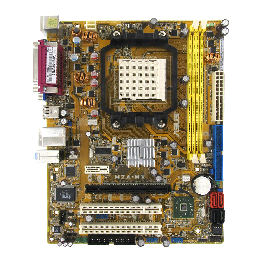
T : Mouse B: Keyboard ATX12V F_USB34 CPU_FAN LAN1_USB12 690V 951462AGLF AUDIO PCIEX1_1 Attansic CHA_FAN M2A-MX CR2032 3V Lithium Cell PCIEX16 CMOS Power CHASSIS Super I/O PCI1 SB600 USB56 PCI2 ALC662 BIOS SPDIF_OUT FLOPPY F_PANEL USB78 USB910 AAFP SPEAKER ASUS M2A-MX... -
Page 20: Placement Direction
Place six (6) screws into the holes indicated by circles to secure the motherboard to the chassis. Do not overtighten the screws! Doing so can damage the motherboard. Place this side towards the rear of the chassis M2A-MX Chapter 1: Product introduction... -
Page 21: Central Processing Unit (Cpu)
1.6.1 Installing the CPU To install a CPU. Locate the CPU socket on the motherboard. M2A-MX M2A-MX CPU Socket M2 Unlock the socket by pressing the lever sideways, then lift it up to a 90°-100° angle. Socket lever Make sure that the socket lever is lifted up to 90°-100° angle, otherwise the CPU does not fit in completely. - Page 22 Connect the CPU fan cable to the CPU_FAN connector on the motherboard. CPU_FAN M2A-MX M2A-MX CPU Fan Connector Do not forget to connect the CPU fan connector! Hardware monitoring errors can occur if you fail to plug this connector. 1-10...
-
Page 23: Installing The Heatsink And Fan
Retention bracket lock Your boxed CPU heatsink and fan assembly should come with installation instructions for the CPU, heatsink, and the retention mechanism. If the instructions in this section do not match the CPU documentation, follow the latter. ASUS M2A-MX 1-11... - Page 24 Attach one end of the retention bracket to the retention module base. Align the other end of the retention bracket (near the retention bracket lock) to the retention module base. A clicking sound denotes that the retention bracket is in place. Make sure that the fan and heatsink assembly perfectly fits the retention mechanism module...
-
Page 25: System Memory
240-pin footprint compared to the 184-pin DDR DIMM. DDR2 DIMMs are notched differently to prevent installation on a DDR DIMM socket. The figure illustrates the location of the DDR2 DIMM sockets: M2A-MX M2A-MX 240-pin DDR2 DIMM Sockets Channel Sockets Channel A... - Page 26 • When using only one memory module, start installing the DDR2 DIMM from slot DIMM_A1 or DIMM_B1 for better overclocking capability. • Always use identical DDR2 DIMM pairs for dual channel mode. For optimum compatibility, we recommend that you obtain memory modules from the same vendor.
- Page 27 HYB18T512800AF37FSS29334 • 512MB REMAXEL RML1040EG38D6F-533 E5108AG-5C-E • • 256MB Samsung M378T3253FG0-CD5 K4T56083QF-GCD5 • 512MB Samsung M378T6553BG0-CD5 K4T51083QB-GCD5 • 512MB Transcend 512MB DDR2 533 ECC 6ND22D9GCT(ECC) • 512MB VERITECH GTP512HLTM46DG VTD264M8PC6G01A164129621 • • VERITECH GTP01GHLTM56DG VTD264M8PC6G01A164129621 • • ASUS M2A-MX 1-15...
- Page 28 Qualified Vendors Lists (QVL) DDR2-667 MHz capability DIMM support Size Vendor Model Side(s) Component 512MB ADATA M20EL5G3H3160B1C0Z E5108AE-6E-E • 513MB ADATA M20AD5G3H3166I1C52 AD29608A8A-3EG20648 • ADATA M2OAD5G3I4176I1C52 AD29608A8A-3EG20645 • 512MB AENEON AET660UD00-30DA98Z AET93F30DA 0552 • • 512MB AENEON AET660UD00-30DB97X AET93R300B 0634 •...
- Page 29 VDATA M2GVD5G3H31A4I1C52 VD29608A8A-3EC20615 • 512MB VDATA M2YVD5G3H31P4I1C52 VD29608A8A-3EG20627 • 512MB VDATA M2GVD5G3H166I1C52 VD29608A8A-3EG20637 • VDATA M2GVD5G3I41P6I1C52 VD29608A8A-3EG20627 • VDATA M2GVD5G3I41C4I1C52 VD29608A8A-3EC20620 • VDATA M2GVD5G3I4176I1C52 VD29608A8A-3EG20641 • 512MB VERITECH GTP512HLTM45EG VTD264M8PC6G01A164129621 • • VERITECH GTP01GHLTM55EG VTD264M8PC6G01A164129621 • • ASUS M2A-MX 1-17...
-
Page 30: Channel Memory Configuration
A - Supports one module inserted in any slot as Single-channel memory configuration B - Supports one pair of modules inserted into either the yellow slots as one pair of Dual- channel memory configuration Visit the ASUS website for the latest DDR2 DIMM modules for this motherboard. 1-18 Chapter 1: Product introduction... -
Page 31: Installing A Dimm
DIMM. DDR2 DIMM notch Support the DIMM lightly with your fingers when pressing the retaining clips. The DIMM might get damaged when it flips out with extra force. Remove the DIMM from the socket. ASUS M2A-MX 1-19... -
Page 32: Expansion Slots
Expansion slots In the future, you may need to install expansion cards. The following sub-sections describe the slots and the expansion cards that they support. Make sure to unplug the power cord before adding or removing expansion cards. Failure to do so may cause you physical injury and damage motherboard components. -
Page 33: Interrupt Assignments
(free) System CMOS/real time clock (free) Standard PCI Graphics Adapter (VGA) Sata controller PS/2 Port Mouse controller Numeric data processor Primary IDE controller Secondary IDE controller * These IRQs are usually available for ISA or PCI devices. ASUS M2A-MX 1-21... -
Page 34: Irq Assignments For This Motherboard
IRQ assignments for this motherboard PCIE X1 SLOT shared PCIE X16 SLOT shared Onboard USB1.1 Controller 1 shared Onboard USB1.1 Controller 2 shared Onboard USB1.1 Controller 3 shared Onboard USB1.1 Controller 4 shared Onboard USB1.1 Controller 5 shared Onboard USB2.0 Controller shared Onboard ATI RS690 AZALIA shared... -
Page 35: Pci Slots
PCI Express x1 slot. 1.8.5 PCI Express x16 slot This motherboard has supports PCI Express x16 graphic cards that comply with PCI Express specifications. The figure shows a graphics card installed on the PCI Express x16 slot. ASUS M2A-MX 1-23... -
Page 36: Jumpers
Normal Clear RTC (Default) M2A-MX Clear RTC RAM You do not need to clear the RTC when the system hangs due to overclocking. For system failure due to overclocking, use the C.P.R. (CPU Parameter Recall) feature. Shut down and reboot the system so the BIOS can automatically reset parameter settings to default values. - Page 37 USB devices. Set to +5VSB to wake up from S3 and S4 sleep modes. PS2_USBPW M2A-MX M2A-MX USB Device Wake Up • The USB device wake-up feature requires a power supply that can provide 500mA on the +5VSB lead for each USB port; otherwise, the system will not power up.
-
Page 38: 1.10 Connectors
1.10 Connectors 1.10.1 Rear panel connectors PS/2 mouse port (green). This port is for a PS/2 mouse. Parallel port. This 25-pin port connects a parallel printer, a scanner, or other devices. LAN (RJ-45) port. This port allows Gigabit connection to a Local Area Network (LAN) through a network hub. - Page 39 Video Graphics Adapter (VGA) port. This 15-pin port is for a VGA monitor or other VGA-compatible devices. 10. Serial (COM1) port. This port is for pointing devices or other serial devices. 11. PS/2 keyboard port (purple). This port is for a PS/2 keyboard. ASUS M2A-MX 1-27...
-
Page 40: Internal Connectors
PIN1 NOTE: Orient the red markings on the floppy ribbon cable to PIN 1. M2A-MX Floppy Disk Drive Connector Chassis intrusion connector (4-1 pin CHASSIS) This connector is for a chassis-mounted intrusion detection sensor or switch. Connect one end of the chassis intrusion sensor or switch cable to this connector. - Page 41 IDE cable. • Use the 80-conductor IDE cable for Ultra DMA 133 / 100 / 66 IDE devices. If any device jumper is set as “Cable-Select,” make sure all other device jumpers have the same setting. M2A-MX ASUS M2A-MX 1-29...
- Page 42 RSATA_TXN4 RSATA_RXP3 RSATA_RXP4 RSATA_TXN3 RSATA_TXP3 RSATA_RXN4 M2A-MX SATA Connectors Install the Windows XP Service Pack 1 before using Serial ATA. ® • For detailed instructions on how to configure RAID 0, RAID 1, and RAID 0+1, refer to the RAID manual in the support CD.
- Page 43 This connector is for an additional Sony/Philips Digital Interface (S/PDIF) port(s). Connect the S/PDIF module cable to this connector, then install the module to a slot opening at the back of the system chassis. M2A-MX M2A-MX Digital Audio Connector The S/PDIF module is purchased separately. ASUS M2A-MX 1-31...
- Page 44 480 Mbps connection speed. USB56 USB78 USB910 M2A-MX Never connect a 1394 cable to the USB connectors. Doing so will damage the motherboard! The USB 2.0 module is purchased separately. Optical drive audio in connector (4-pin CD) These connectors allow you to receive stereo audio input from sound sources such as a CD-ROM, TV tuner, or MPEG card.
-
Page 45: Speaker/Front Panel Audio Connector
Front Panel Select item in the BIOS is set AC`97 to [HD Audio]; if you want to connect an front panel audio module to this connector, set the item to [AC97]. See page 2-25 for details. ASUS M2A-MX 1-33... - Page 46 These connectors are for an ATX power supply. The plugs from the power supply are designed to fit these connectors in only one orientation. Find the proper orientation and push down firmly until the connectors completely fit. M2A-MX • We recommend that you use an ATX 12 V Specification 2.0-compliant power supply unit (PSU) with a minimum of 300 W power rating.
-
Page 47: System Panel Connector (10-1 Pin Panel)
BIOS settings. Pressing the power switch for more than four seconds while the system is ON turns the system OFF. Reset button (2-pin RESET) • This 2-pin connector is for the chassis-mounted reset button for system reboot without turning off the system power. ASUS M2A-MX 1-35... - Page 48 1-36 Chapter 1: Product introduction...
-
Page 49: Chapter 2: Bios Setup
This chapter tells how to change the system settings through the BIOS Setup menus. Detailed descriptions of the BIOS parameters are also provided. BIOS setup... -
Page 50: Managing And Updating Your Bios
ASUS Update: Updates the BIOS in Windows environment. ® ASUS EZ Flash: Updates the BIOS in DOS mode using a floppy disk or the motherboard support CD. ASUS AFUDOS: Updates the BIOS in DOS mode using a bootable floppy disk. -
Page 51: Updating Bios Through Internet
To update the BIOS through the Internet: Launch the ASUS Update utility from the Windows desktop by clicking Start ® > Programs > ASUS > ASUSUpdate > ASUSUpdate. The ASUS Update main window appears. Select Update BIOS from the Select the ASUS FTP site nearest... - Page 52 To update the BIOS through a BIOS file: Launch the ASUS Update utility from the Windows desktop by clicking Start ® > Programs > ASUS > ASUSUpdate > ASUSUpdate. The ASUS Update main window appears. Select Update BIOS from a file option from the drop-down menu, then click Next.
-
Page 53: Creating A Bootable Floppy Disk
Right-click Floppy Disk Drive then click Format to display the Format 3 1/2 Floppy dialog box. d. Select the Create an MS-DOS startup disk check box. e. Click Start. Copy the original or the latest motherboard BIOS file to the bootable floppy disk. ASUS M2A-MX... -
Page 54: Asus Ez Flash Utility
2.1.3 ASUS EZ Flash utility The ASUS EZ Flash feature allows you to update the BIOS without having to go through the long process of booting from a floppy disk and using a DOS-based utility. The EZ Flash utility is built-in the BIOS chip so it is accessible by pressing <Alt>... -
Page 55: Afudos Utility
Extension name Press <Enter>. The utility copies the current BIOS file to the floppy disk. A:\>afudos /oOLDBIOS1.rom AMI Firmware Update Utility - Version 1.19(ASUS V2.07(03.11.24BB)) Copyright (C) 2002 American Megatrends, Inc. All rights reserved. Reading flash ..done Write to file..ok A:\>... -
Page 56: Updating The Bios File
Updating the BIOS file To update the BIOS file using the AFUDOS utility: Visit the ASUS website (www.asus.com) and download the latest BIOS file for the motherboard. Save the BIOS file to a bootable floppy disk. Write the BIOS filename on a piece of paper. You need to type the exact BIOS filename at the DOS prompt. -
Page 57: Asus Crashfree Bios 2 Utility
2.1.5 ASUS CrashFree BIOS 2 utility The ASUS CrashFree BIOS 2 is an auto recovery tool that allows you to restore the BIOS file when it fails or gets corrupted during the updating process. You can update a corrupted BIOS file using the motherboard support CD or the floppy disk that contains the updated BIOS file. -
Page 58: Recovering The Bios From The Support Cd
Start flashing... Restart the system after the utility completes the updating process. The recovered BIOS may not be the latest BIOS version for this motherboard. Visit the ASUS website (www.asus.com) to download the latest BIOS file. 2-10 Chapter 2: BIOS setup... -
Page 59: Bios Setup Program
The BIOS setup screens shown in this section are for reference purposes only, and may not exactly match what you see on your screen. • Visit the ASUS website (www.asus.com) to download the latest BIOS file for this motherboard. ASUS M2A-MX... -
Page 60: Bios Menu Screen
2.2.1 BIOS menu screen Menu items Menu bar Configuration fields General help Exit System Time [05: 18 : 44] Use [ENTER], [TAB] System Date [Wed01/30/2002] or [SHIFT-TAB] to Legacy Diskette A [1.44M, 3.5in.] select a field. Primary IDE Master : [Not Detected] Use [+] or [-] to Primary IDE Slave : [Not Detected]... -
Page 61: Menu Items
ICH Delayed Transaction [Enabled] Change Option General Help MPS Revision [1.4] Save and Exit Exit 2.2.8 General help Pop-up window At the top right corner of the menu screen is a brief description of the selected item. ASUS M2A-MX 2-13... -
Page 62: Main Menu
Main menu When you enter the BIOS Setup program, the Main menu screen appears, giving you an overview of the basic system information. Refer to section “2.2.1 BIOS menu screen” for information on the menu screen items and how to navigate through them. Exit Use [ENTER], [TAB] System Time... -
Page 63: Primary Ide Master/Slave
When set to [Disabled], the data transfer from and to the device occurs one sector at a time. Configuration options: [Disabled] [Auto] ASUS M2A-MX 2-15... -
Page 64: Sata1, Sata2, Sata3, And Sata4
PIO Mode [Auto] Selects the PIO mode. Configuration options: [Auto] [0] [1] [2] [3] [4] DMA Mode [Auto] Selects the DMA mode. Configuration options: [Auto] [SWDMA0] [SWDMA1] [SWDMA2] [MWDMA0] [MWDMA1] [MWDMA2] [UDMA0] [UDMA1] [UDMA2] [UDMA3] [UDMA4] [UDMA5] SMART Monitoring [Auto] Sets the Smart Monitoring, Analysis, and Reporting Technology. -
Page 65: Ide Configuration
[SATA] Disabled Onboard SATA Channel [Enabled] Allows you to enable or disable the onboard SATA channel. Configuration options: [Disabled] [Enabled] OnChip SATA Type [SATA] Allows you to select the onchip SATA type. Configuration options: [SATA] [RAID] [AHCI] ASUS M2A-MX 2-17... -
Page 66: System Information
2.3.7 System Information This menu gives you an overview of the general system specifications. The BIOS automatically detects the items in this menu. AMIBIOS Version : 0115 Build Date : 10/08/07 Processor Type : AMD Sempron(tm) Processor 3200+ Speed : 1807MHz Count System Memory Installed Size: 512MB... -
Page 67: Advanced Menu
Frequencies higher than CPU manufacturer recommends are not guaranteed to be stable. If the system becomes unstable, return to the default. Configuration options: [Auto] [Manual] [Standard] The following item appears only when the AI Overclocking item is set to [MANUAL]. ASUS M2A-MX 2-19... - Page 68 CPU/HT Reference Clock (MHz) [200] Displays the frequency sent by the clock generator to the system bus and PCI bus. The value of this item is auto-detected by the BIOS. Use the <+> and <-> keys to adjust the CPU frequency. You can also type the desired CPU frequency using the numeric keypad.
-
Page 69: Cpu Configuration
Configuration options: [Disabled] [Enabled] Microcode Updation [Enabled] Enables or disables the microcode updation. Configuration options: [Disabled] [Enabled] Cool ’n’ Quiet [Enabled] Enables or disables the AMD Cool ’n’ Quiet function. Configuration options: [Disabled] [Enabled] ASUS M2A-MX 2-21... -
Page 70: Chipset
2.4.3 Chipset The Chipset menu allows you to change the advanced chipset settings. Select an item then press <Enter> to display the sub-menu. Memory Options & Advanced Chipset Settings Information WARNING: Setting wrong values in below sections may cause system to malfunction. -
Page 71: Dram Timing Configuration
DRAM Timing Mode [Auto] Allows you to select the DRAM timing mode. Configuration options: [Auto] [DCT 0] Memory Voltage [Auto] Allows you to set the memory voltage. Configuration options: [1.890V] [1.940V] [1.990V] [2.040V] [2.090V] [2.140V] [2.190V] [2.240V] ASUS M2A-MX 2-23... -
Page 72: Internal Graphics
Alternate VID [Auto] Allows you to specify the alternate VID while in low power states. Configuration options: [1.000V] [0.975V] [0.950V] [0.925V] [0.900V] [0.875V] [0.850V] [0.825V] [0.800V] [Auto] Internal Graphics Internal Grahpics Options Internal Grahpics Mode [UMA] UMA Frame Buffer Size [Auto] Current UMA Size [64MB]... -
Page 73: Onboard Devices Configuration
Configuration options: [AC97] [HD Audio] OnBoard LAN Controller [Enabled] Allows you to enable or disable onboard LAN. Configuration options: [Disabled] [Enabled] OnBoard LAN Boot ROM [Disabled] Allows you to configure LAN boot ROM. Configuration options: [Disabled] [Enabled] ASUS M2A-MX 2-25... -
Page 74: Pci Pnp
2.4.5 PCI PnP The PCI PnP menu items allow you to change the advanced settings for PCI/PnP devices. The menu includes setting IRQ and DMA channel resources for either PCI/PnP or legacy ISA devices, and setting the memory size block for legacy ISA devices. -
Page 75: Usb Configuration
BIOS EHCI Hand-Off [Enabled] Allows you to enable or disable BIOS EHCI Hand-Off. This is a workaround for OS without EHCI hand-off support. The EHCI ownership change should be claimed by EHCI driver. Configuration options: [Disabled] [Enabled] ASUS M2A-MX 2-27... -
Page 76: Power Menu
USB Mass Storage Device Configuration USB Mass Storage DeviceConfiguration Numer of seconds POST waits for the USB Mass Storage Reset Delay [20 Sec] USB mass storage device after start Device #1 Netac unit command. Emulation Type [Auto] USB Mass Storage Reset Delay [20 Sec] Allows you to select the USB mass storage reset delay time. -
Page 77: Apm Configuration
Allows you to enable or disable RTC to generate a wake event. When this item is set to Enabled, the items RTC Alarm Date, RTC Alarm Hour, RTC Alarm Minute, and RTC Alarm Second appear with set values. Configuration options: [Disabled] [Enabled] ASUS M2A-MX 2-29... -
Page 78: Hardware Monitor
2.5.5 Hardware Monitor CPU Temperature Hardware Monitor CPU Temperature [38ºC/100ºF] CPU Fan Speed [3260RPM] Chassis Fan Speed [N/A] VCORE Voltage [ 1.424V] 3.3V Voltage [ 3.296V] 5V Voltage [ 5.068V] 12V Voltage [12.416V] Smart Q-FAN Function [Disabled] CPU Temperature [xxxºC/xxxºF] [Ignored] The onboard hardware monitor automatically detects and displays the motherboard and CPU temperatures. -
Page 79: Boot Menu
These items specify the boot device priority sequence from the available devices. The number of device items that appears on the screen depends on the number of devices installed in the system. Configuration options: [xxxxx Drive] [Disabled] ASUS M2A-MX 2-31... -
Page 80: Boot Settings Configuration
This allows you to enable or disable the full screen logo display feature. Configuration options: [Disabled] [Enabled] Set this item to [Enabled] to use the ASUS MyLogo™ feature. Add On ROM Display Mode [Force BIOS] Sets the display mode for option ROM. Configuration options: [Force BIOS]... -
Page 81: Security
<Enter>. The message “Password Uninstalled” appears. If you forgot your BIOS password, you can clear it by erasing the CMOS Real Time Clock (RTC) RAM. See section “1.9 Jumpers” for information on how to erase the RTC RAM. ASUS M2A-MX 2-33... -
Page 82: Change User Password
After you have set a supervisor password, the other items appear to allow you to change other security settings. <Enter> to change Security Settings password. <Enter> again to Supervisor Password : Not Installed disabled password. User Password : Not Installed Change Supervisor Password User Access Level [Full Access]... -
Page 83: Exit Menu
If you attempt to exit the Setup program without saving your changes, the program prompts you with a message asking if you want to save your changes before exiting. Press <Enter> to save the changes while exiting. ASUS M2A-MX 2-35... -
Page 84: Discard Changes
Exit & Discard Changes Select this option only if you do not want to save the changes that you made to the Setup program. If you made changes to fields other than System Date, System Time, and Password, the BIOS asks for a confirmation before exiting. Discard Changes This option allows you to discard the selections you made and restore the previously saved values. -
Page 85: Chapter 3: Software Support
This chapter describes the contents of the support CD that comes with the motherboard package. Software support... -
Page 86: Installing An Operating System
The contents of the support CD are subject to change at any time without notice. Visit the ASUS website(www.asus.com) for updates. 3.2.1 Running the support CD Place the support CD to the optical drive. The CD automatically displays the Drivers menu if Autorun is enabled in your computer. -
Page 87: Drivers Menu
The drivers menu shows the available device drivers if the system detects installed devices. Install the necessary drivers to activate the devices. ASUS InstAll - Drivers Installation Wizard Launches the ASUS InstAll driver installation wizard. AMD Cool ‘n’ Quiet Driver Installs the AMD Cool ‘n’ Quiet driver. -
Page 88: Utilities Menu
ASUS InstAll - Installation Wizard for Utilities Launches the ASUS InstAll utilities installation wizard. ASUS Update The ASUS Update utility allows you to update the motherboard BIOS in a Windows environment. This utility requires an Internet connection either through a ®... -
Page 89: Make Disk Menu
The Manual menu contains a list of supplementary user manuals. Click an item to open the folder of the user manual. Most user manual files are in Portable Document Format (PDF). Install the Adobe Acrobat Reader from the Utilities menu before opening a user manual ® ® file. ASUS M2A-MX... -
Page 90: Asus Contact Information
3.2.6 ASUS Contact information Click the Contact tab to display the ASUS contact information. You can also find this information on the inside front cover of this user guide. 3.2.7 Other information The icons on the top right corner of the screen give additional information on the motherboard and the contents of the support CD. -
Page 91: Technical Support Form
Browse this CD Displays the support CD contents in graphical format. Technical support Form Displays the ASUS Technical Support Request Form that you have to fill out when requesting technical support. Filelist Displays the contents of the support CD and a brief description of each in text format. - Page 92 Chapter 3: Software support...