3Com 5500-EI PWR Getting Started Manual
Switch 5500 family
Hide thumbs
Also See for 5500-EI PWR:
- Reference manual (1314 pages) ,
- Install manual (1072 pages) ,
- Quick reference manual (59 pages)
Table of Contents
Advertisement
Quick Links
Advertisement
Table of Contents

Related Manuals for 3Com 5500-EI PWR


Summary of Contents for 3Com 5500-EI PWR
-
Page 1: Switch 5500 Family
SuperStack ® Switch 5500 Family Getting Started Guide Switch 5500-SI 28-Port (3CR17151-91) Switch 5500-SI 52-Port (3CR17152-91) Switch 5500-EI 28-Port (3CR17161-91) Switch 5500-EI 52-Port (3CR17162-91) http://www.3com.com/ Part No. DUA1715-0AAA02 Published April 2005... -
Page 2: Superstack
3Com Corporation reserves the right to revise this documentation and to make changes in content from time MA 01752-3064 to time without obligation on the part of 3Com Corporation to provide notification of such revision or change. 3Com Corporation provides this documentation without warranty, term, or condition of any kind, either implied or expressed, including, but not limited to, the implied warranties, terms or conditions of merchantability, satisfactory quality, and fitness for a particular purpose. -
Page 3: Table Of Contents
ONTENTS BOUT UIDE Before You Start Release Notes About Your CD-ROM Conventions Related Documentation Accessing Online Documentation Documentation Comments NTRODUCING THE 5500 F UPER TACK WITCH AMILY About the Switch 5500 Summary of Hardware Features Switch 5500 — Front View Detail 10BASE-T/ 100BASE-TX Ports 1000BASE-X SFP Ports Console Port... - Page 4 Manually Configuring IP Information Connecting to the Console Port Connecting to a Front Panel Port Viewing Automatically Configured IP Information Using 3Com Network Director Connecting to the Console Port Setting Up Command Line Interface Management User Interface Overview CLI Management via the Console Port...
- Page 5 Setting Up SNMP Management V1 or V2 Pre-requisites Default Users and Passwords Configuration Conversion Utility XRN S REATING AN TACKING ABRIC How To Interconnect Units Guidelines For Interconnecting Units Unit Numbering within the Fabric ROBLEM OLVING Solving Problems Indicated by LEDs Solving Hardware Problems Solving Communication Problems Solving Fabric Formation Problems...
- Page 6 L’information de Sécurité Importante Wichtige Sicherheitsinformationen Información de Seguridad Importante Importanti Informazioni di Sicurezza Ważne informacje o zabezpieczeniach OUTS Null Modem Cable PC-AT Serial Cable Modem Cable Ethernet Port RJ-45 Pin Assignments ECHNICAL PECIFICATIONS Switch 5500-SI Switch 5500-EI Earthing Lead BTAINING UPPORT FOR YOUR RODUCT...
-
Page 7: About This Guide
BOUT UIDE This guide provides all the information you need to install and use the following switches in their default state: ® SuperStack 4 Switch 5500-SI 28-Port (3CR17151-91) ■ ® SuperStack 4 Switch 5500-SI 52-Port (3CR17152-91) ■ SuperStack ® 4 Switch 5500-EI 28-Port (3CR17161-91) ■... -
Page 8: About Your Cd-Rom
A link to 3Com Network Director software. ■ A number of other useful links. ■ Most user guides and release notes are available in Adobe Acrobat Reader Portable Document Format (PDF) or HTML on the 3Com World Wide Web site: http://www.3com.com/ Conventions Table 1 Table 2 list conventions that are used throughout this guide. -
Page 9: Related Documentation
Related Documentation Table 2 Text Conventions (continued) Convention Description The words “enter” When you see the word “enter” in this guide, you must type and “type” something, and then press Return or Enter. Do not press Return or Enter when an instruction simply says “type.” Keyboard key names If you must press two or more keys simultaneously, the key names are linked with a plus sign (+). -
Page 10: Accessing Online Documentation
BOUT UIDE SuperStack 4 Switch Command Reference Guide ■ This guide provides detailed information about the web interface and command line interface that enable you to manage the Switch. It is supplied in PDF format on the CD-ROM that accompanies the Switch. Release Notes ■... -
Page 11: Documentation Comments
SuperStack 4 Switch 5500 Family Getting Started Guide Page 21 Please note that we can only respond to comments and questions about 3Com product documentation at this e-mail address. Questions related to technical support or sales should be directed in the first instance to your network supplier. - Page 12 BOUT UIDE...
-
Page 13: Introducing The Super Stack 4 Switch 5500 Family
NTRODUCING THE 5500 UPER TACK WITCH AMILY This chapter contains introductory information about the Switch 5500 and how it can be used in your network. It covers summaries of hardware and software features and also the following topics: About the Switch 5500 ■... -
Page 14: About The Switch 5500
1: I 5500 F HAPTER NTRODUCING THE UPER TACK WITCH AMILY About the Switch The Switch 5500 Family are mixed media devices which consist of: 5500 24 or 48 10BASE-T/100BASE-TX ports ■ 4 1000BASE-X SFP ports ■ 1 RJ-45 connector for serial management ■... -
Page 15: Switch 5500 - Front View Detail
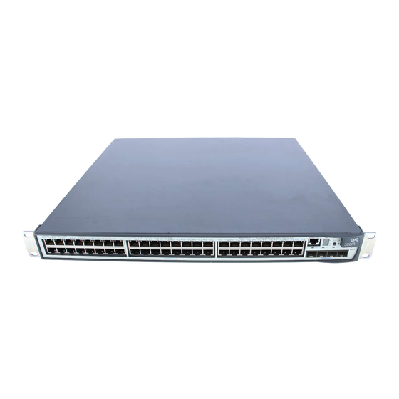
Switch 5500 — Front View Detail Switch 5500 — Front View Detail Figure 1 Switch 5500-SI and Switch 5500-EI 28-Port — front view Port Status LEDs Console Port RPS LED Power LED 10/100BASE-TX Ports 1000BASE-X Ports Unit LED Mode LED Figure 2 Switch 5500-SI and Switch 5500-EI 52-Port - front view Port Status LEDs Console Port... -
Page 16: 1000Base-X Sfp Ports
1: I 5500 F HAPTER NTRODUCING THE UPER TACK WITCH AMILY 1000BASE-X SFP Ports SFP (Small Form Factor Pluggable) ports support fiber Gigabit Ethernet short-wave (SX), long-wave (LX), long-haul (LH70) and copper (T) SFP Transceivers in any combination. This offers you the flexibility of using SFP transceivers to provide connectivity between the Switch and remote 1000 Mbps workgroups or to create a high capacity aggregated link backbone connection. - Page 17 Switch 5500 — Front View Detail Color Indicates Green flashing ‘t’ The Switch is over temperature and unit temperature is critical. PWR LED Green The Switch is powered-up and operating normally. Green flashing Self Test (POST) or Software Download is in progress. Yellow flashing One or more ports have failed POST.
-
Page 18: Switch 5500 - Rear View Detail
1: I 5500 F HAPTER NTRODUCING THE UPER TACK WITCH AMILY Color Indicates Yellow Half duplex packets are being transmitted/received on the port. Yellow flashing Port failed POST. No link is present. Switch 5500 — Rear Figure 3 Switch 5500 SI and EI — rear view View Detail Open Book Warning Labels Power Socket... -
Page 19: Default Settings
Default Settings Default Settings Table 5 shows the default settings for the Switch 5500 Family: Table 5 Default Settings Feature Switch 5500 Automatic IP Configuration Enabled Port Status Enabled Port Speed Auto-negotiated Duplex Mode Auto-negotiated Flow Control Auto-negotiated Broadcast Storm Control Enabled Virtual LANs (VLANs) All ports belong to the untagged Default VLAN... - Page 20 1: I 5500 F HAPTER NTRODUCING THE UPER TACK WITCH AMILY...
-
Page 21: Installing The Switch
NSTALLING THE WITCH This chapter contains the information you need to install and set up the Switch 5500. It covers the following topics: Package Contents ■ Choosing a Suitable Site ■ Rack-mounting ■ Connecting a Redundant Power Supply ■ Placing Units On Top of Each Other ■... -
Page 22: Package Contents
2: I HAPTER NSTALLING THE WITCH AVVERTENZA: Informazioni di sicurezza. Prima di installare o rimuovere qualsiasi componente dal Switch 5500 o di eseguire qualsiasi procedura di manutenzione, leggere le informazioni di sicurezza riportate nell'Appendice A della presente guida per l'utente. OSTRZEŻENIE: Informacje o zabezpieczeniach. -
Page 23: Rack-Mounting
■ Air flow is not restricted around the Switch or through the vents in the ■ side of the Switch. 3Com recommends that you provide a minimum of 25mm (1in.) clearance. Air temperature around the Switch does not exceed 40 (104 °C... - Page 24 3Com product name of the Switch ■ 3Com 3C number of the Switch ■ Unique MAC address (Ethernet address) of the Switch ■ Serial number of the Switch ■ You may need this information if you contact 3Com Technical Support.
-
Page 25: Connecting A Redundant Power Supply
Connecting a Redundant Power Supply Connecting a The Switch 5500 has an unearthed 48V DC Redundant Power Supply Redundant Power socket. Supply WARNING: The installation of the Redundant Power Supply (RPS) should only be carried out by properly trained and qualified personnel. WARNING: These instructions must be read in conjunction with the RPS flyer and the safety and installation instructions supplied with your RPS. - Page 26 AC mains AC mains and RPS The unit is powered by the RPS. 3Com’s RPS solution uses 48V DC power distribution. The RPS system provides bulk 48V DC power that is separately distributed to a number of network switches. Each RPS consists of a shelf which can house from one to six rectifiers, a Distribution Module and a Management Module.
-
Page 27: Specifying The Redundant Power System
Redundant Power full set of requirements go to: System http://www.3Com.com/RPS 3Com’s redundant power solution allows the use of any off-the-shelf 48V DC RPS that provides an ‘unearthed SELV’ output in compliance with IEC 60950-1/UL 60950-1/EN 60950-1, as defined in Appendix C page 105. -
Page 28: Connecting The Earthing Cable
2: I HAPTER NSTALLING THE WITCH Connecting the Use the earthing cable that accompanies your Switch if the length is Earthing Cable suitable, alternatively use the earthing cable specification as defined in Appendix C page 105. The recommended cable length should not exceed 3 metres (9.84 feet). WARNING: RPS Manufacturers recommendations must be followed when connecting the cable to the RPS. -
Page 29: Rps Led
Connecting a Redundant Power Supply Figure 5 RPS Connection to the Switch N U LL 0 V ;2 .0 -4 8 -6 z ;1 .0 A 0 /6 0 H 4 0 V ;5 1 0 0 -2 Cable Tie NULL -48 -60V;2 0A Null... -
Page 30: Placing Units On Top Of Each Other
2: I HAPTER NSTALLING THE WITCH Placing Units On If the Switch units are free-standing, up to eight units can be placed one Top of Each Other ® on top of the other. If you are mixing a variety of SuperStack units, the smaller units must be positioned at the top. -
Page 31: Sfp Operation
■ 3CSFP93 SFP (1000BASE-T) ■ To access the latest list of approved SFP transceivers for the Switch on the 3Com Corporation World Wide Web site, enter this URL into your internet browser: http://www.3com.com Inserting an SFP To be recognized as valid, the SFP transceiver must have the following... - Page 32 If the SFP transceiver is faulty, it will not operate within the Switch. See “Solving Hardware Problems” page 3Com recommends that you only use SFPs supplied by 3Com. If the SFP transceiver is invalid it will not be recognized by the Switch. Use the following sequence of steps to activate the SFP ports: 1 The SFP transceiver is keyed and there is only one way in which it can be installed correctly.
-
Page 33: Removing An Sfp Transceiver
Choosing the Correct Cables Product label Suitable port on host Switch 5 Use an appropriate cable to connect the transceiver to a suitable device. 6 Check the LEDs on the front of the Switch to ensure that it is operating correctly. - Page 34 NSTALLING THE WITCH 3Com recommends that you use at least Category 5 twisted pair cable — the maximum segment length for this type of cable is 100 m (328 ft.). Table 11 Cables required to connect the Switch to other devices if...
-
Page 35: Setting U P For Management
ETTING P FOR ANAGEMENT To make full use of the features offered by your Switch, and to change and monitor the way it works, you have to access the management software that resides on the Switch. This is known as managing the Switch. -
Page 36: Methods Of Managing A Switch
3: S HAPTER ETTING P FOR ANAGEMENT Methods of To manage your Switch you can use one of the following methods: Managing a Switch Command line interface management ■ Command line interface management using SSH ■ Web interface management ■ SNMP management ■... -
Page 37: Command Line Interface Management Using Ssh
You can manage a Switch using any network management workstation running the Simple Network Management Protocol (SNMP) as shown in Figure 10. For example, you can use the 3Com Network Director software, available from the 3Com website. Figure 10 SNMP Management over the Network... -
Page 38: Setting Up Overview
How do you want to connect to the Switch? configured IP information? Connect to the con- Connect to a front panel port Use 3Com Network Connect to the console sole port and use the and use the Web Interface or Director (3ND). -
Page 39: Ip Configuration
(Static IP addresses are necessary to ensure that the Switch is always allocated the same IP information.) For most installations, 3Com recommends that you configure the Switch IP information manually. This makes management simpler and more reliable as it is not dependent on a DHCP or BootP server, and eliminates the risk of the IP address changing. -
Page 40: Preparing For Management
For detailed information about the specific web interface operations and command line interface commands and problem solving, refer to the “SuperStack 4 Switch Command Reference Guide” on the CD-ROM that is supplied with the Switch or on the 3Com Web site. -
Page 41: Manually Configuring Ip Information
Manually Configuring IP Information Manually You can manually configure the Switch IP information in the following Configuring IP ways: Information Connecting to the console port — connect a workstation using a ■ console cable to the console port of the Switch. You can then manually enter IP information using the command line interface (CLI). - Page 42 3: S HAPTER ETTING P FOR ANAGEMENT Connecting the Workstation to the Switch 1 Connect the workstation to the console port using the console cable as shown in Figure Figure 12 Connecting a Workstation to the Switch via the Console Port Workstation Switch (with terminal emulation...
- Page 43 Manually Configuring IP Information 2 At the login and password prompts, enter as your user name and admin press Return and at the password prompt press Return again. If you have logged on correctly, <5500-xx> should be displayed (where xx is either SI or EI) as shown in Figure Once you have logged in you will automatically be in User View.
-
Page 44: Connecting To A Front Panel Port
3: S HAPTER ETTING P FOR ANAGEMENT The initial set up of your Switch is now complete and the Switch is ready for you to set up your chosen management method. See “Methods of Managing a Switch” page If you do not intend to use the command line interface via the console port to manage the Switch, you can disconnect the serial cable and close the terminal emulator software. - Page 45 Manually Configuring IP Information Connecting the Workstation to the Switch 1 Connect the workstation to a front panel port using an Ethernet cable as shown in Figure Figure 14 Connecting a Workstation to the Switch via a Front Panel Port Switch Workstation (with a Network...
- Page 46 3: S HAPTER ETTING P FOR ANAGEMENT 4 To enter basic setup information for the Switch, select Administration > IP Setup and then follow the wizard through various system screens to enter the IP address and subnet mask that you want the Switch to use when it is connected to the network.
-
Page 47: Viewing Automatically Configured Ip Information
IP information before you can begin to Configured IP manage the Switch. You can discover the IP information in two ways: Information Using 3Com Network Director — this application will auto-discover ■ the Switch and display the automatically allocated IP information assigned to the Switch. -
Page 48: Using 3Com Network Director
DHCP or BootP server. If your network does not have a DHCP or BootP server, the workstation running 3Com Network Director must be on the same subnet as the Switch, because Auto-IP addresses are non-routable. Connecting to the... - Page 49 Viewing Automatically Configured IP Information If the login prompt does not begin immediately, press Return a few times until it starts. 3 At the login and password prompts, enter as your user name and admin press Return at the password prompt. If you have logged on correctly, <5500-xx>...
-
Page 50: Setting Up Command Line Interface Management
3: S HAPTER ETTING P FOR ANAGEMENT Setting Up This section describes how you can set up command line interface Command Line management using a local console port connection or over the network. Interface Management User Interface User interface configuration is provided by the Switch to configure and Overview manage the port data. -
Page 51: Setting Up Command Line Interface Management Using Ssh
SSH connections to the switch will be refused. 4 Install an SSH client application on the workstation you want to use to access the switch. 3Com recommends the following SSH clients; PuTTY, OpenSSH and SSH Communications Security Corp Secure Shell. -
Page 52: Setting Up Web Interface Management
3: S HAPTER ETTING P FOR ANAGEMENT 5 Open an SSH session and access the Switch using the Switch’s IP address and port number. The first time you connect to the switch the client will ask you to confirm that the host key is correct for the device. 6 The Switch and the SSH client will authenticate each other and a secure connection will be established. -
Page 53: Web Management Over The Network
VLAN 1 (the Default VLAN). By default, all ports on the Switch are in VLAN 1. You can use the 3Com Network Director application that is available from the 3Com website to provide SNMP management for your Switch. If you use 3Com Network Director it automatically loads the correct MIBs and necessary files onto your workstation. -
Page 54: Pre-Requisites
3: S HAPTER ETTING P FOR ANAGEMENT Pre-requisites Documentation supplied with the SNMP network management ■ application software. The default read community string is public. To change this setting in System View, enter display snmp community. The default write community string is private. To change this setting in System View, enter display snmp community. -
Page 55: Configuration Conversion Utility
The 3Com Switch 5500 Configuration Conversion Utility (CCU) enables Conversion Utility you to convert the key configuration parameters from a range of 3Com SuperStack II and SuperStack 3 devices to the configuration file format used by your Switch 5500 unit. The utility provides conversion for a... - Page 56 3: S HAPTER ETTING P FOR ANAGEMENT...
-
Page 57: Creating An Xrn Stacking Fabric
Fabric with the Switch 5500-EI units. How To Up to eight 3Com Switch 5500 units can be interconnected to create an Interconnect Units XRN Stacking Fabric and then treated as a single manageable unit with one IP address. - Page 58 4: C XRN S HAPTER REATING AN TACKING ABRIC Table 14 SuperStack 4 Switch 5500 Support for XRN Distributed Fabric Switch Port used XRN support Switch 5500-SI 28-Port Ports 27 (up port) and 28 Only supports DDM (3C17151-91) (down port) using a 1000 Mbps SFP transceiver Switch 5500-SI 52-Port Ports 51 (up port) and 52...
-
Page 59: Guidelines For Interconnecting Units
The maximum number of Switch units that can be interconnected is ■ eight. It is not possible to create a fabric by interconnecting a 3Com Switch ■ 5500 with any other 3Com device (such as 5500G Switch units) or mix Enhanced Image (EI) Switch 5500 units with Standard Image (SI) units. -
Page 60: Unit Numbering Within The Fabric
Fabric, then the Switch with the lowest MAC address assumes the ID in question and the other unit will automatically renumber. 3Com recommends that you manually assign the unit IDs within the Fabric if you wish to have predictability of knowing which units have which IDs at all times. -
Page 61: Problem Solving
ROBLEM OLVING This chapter helps you to diagnose and solve problems you may have with the operation of your Switch. There is also an explanation of IP addressing and upgrading software. The topics covered are: Solving Problems Indicated by LEDs ■... -
Page 62: Solving Problems Indicated By Leds
5: P HAPTER ROBLEM OLVING Solving Problems If the LEDs on the Switch indicate a problem, refer to the list of suggested Indicated by LEDs solutions below. The PWR LED does not light Check that the power cable is firmly connected to the Switch and to the supply outlet. -
Page 63: Solving Hardware Problems
Solving Hardware Problems Auto-negotiation problems will occur with 10BASE-T or 100BASE-T where auto-negotiation is disabled and incorrect cables are being used (cross-over or straight) Auto-negotiation problems will occur with fiber if: The Receiver (RX) and Transceiver (TX) cable connectors are ■... -
Page 64: Solving Communication Problems
RPS supply. 4 If another fan failure warning message is generated via the Command Line Interface or the Web interface, return the unit to 3Com. Unit fails, no SNMP fan failure message is received 1 Power cycle the unit. To do this, remove and reconnect the AC mains supply. - Page 65 If your IP network is internal to your organization only, that is, you do not access the Internet, you may use any arbitrary IP address as long as it is not being used by another device on your network. 3Com suggests you...
-
Page 66: Solving Fabric Formation Problems
5: P HAPTER ROBLEM OLVING use addresses in the range 192.168.0.0 to 192.168.255.255 with a subnet mask of 255.255.255.0. These suggested IP addresses are part of a group of IP addresses that have been set aside specially for use ‘in house’ only. Solving Fabric If you are having problems with correctly forming a fabric, first ensure Formation... -
Page 67: Upgrading Software
PGRADING OFTWARE This chapter describes how to upgrade software to your Switch 5500. It covers the following topics: Upgrading from the Command Line Interface ■ Upgrading from the Bootrom Interface ■ Bootrom Upgrade ■... -
Page 68: Upgrading From The Command Line Interface
6: U HAPTER PGRADING OFTWARE Upgrading from the This section describes how to upgrade files to your Switch from the Command Line Command Line Interface (CLI). Interface Introduction Before upgrading the software to your Switch from the CLI, it is important to check the contents of the flash to ensure that there is enough space to download the new files. -
Page 69: Tftp
Upgrading from the Command Line Interface To delete files from the list for the remaining units in a fabric, replace unit1 with unit2 (on the next line) and so on for each Switch in the fabric. 4 The /unreserved option will cause the file to be deleted from both the flash and the recycle-bin. - Page 70 6: U HAPTER PGRADING OFTWARE (where aaa.aaa.aaa.aaa is the IP address of the TFTP server) s4a indicates the Switch filename, see Table 15 for further details: Table 15 Switch 5500 Filenames Filename Prefix Switch SuperStack 4 Switch 5500-SI software SuperStack 4 Switch 5500-EI software SuperStack 4 Switch 5500 bootrom software 2 To download the Web user interface file, enter: tftp aaa.aaa.aaa.aaa get http.zip...
-
Page 71: Ftp (Via A Network Port)
Upgrading from the Command Line Interface copy unit1>flash:/s4e002_012_000.btm unit2>flash:/ Replace unit2 with unit3 and so on for each Switch in the fabric. Command Line Interface Switch Setup 1 To set the Switch to boot from the new software you have downloaded, enter the following: boot boot-loader unit1>flash:/s4a03_01_00s168.app To set the remaining Switches in the fabric to boot from the new... -
Page 72: Xmodem (Via The Console Cable)
6: U HAPTER PGRADING OFTWARE Information on your FTP server is displayed, logon with your username and password. 2 To download the configuration file, enter: get 3ComOScfg.def The following information is displayed if the download has been successful: 200 PORT command successful. 150 Opening ASCII mode data connection for vrpcfg.def(10986 bytes)..226 Transfer complete. -
Page 73: Upgrading From The Bootrom Interface
Upgrading from the Bootrom Interface 3 As the file is downloading, start the XModem send file process with terminal emulation software, such as Microsoft Hyperterminal. When the file download is complete the message Download successful! is displayed. 4 Repeat steps 1 to 3 for each of the remaining files. Upgrading from the This section describes how to upgrade your Switch from the Bootrom Bootrom Interface... -
Page 74: Tftp
6: U HAPTER PGRADING OFTWARE 3 Select option 3 from the Boot Menu. A file list similar to the following is displayed: Boot menu choice: 3 File Number File Size(bytes) File Name ==================================================== 714784 s4h03_01_00.zip private-data.txt 11043 3ComOScfg.def snmpboots 4529259 s4b03_01_00s168.app 11343 3ComOScfg.cfg... -
Page 75: Ftp
Upgrading from the Bootrom Interface 3. Set XMODEM protocol parameter 0. Return to boot menu Enter your choice(0-3): 2 Select option 1 to display the following: Load File name: Switch IP address: Server IP address: 3 Enter the file name, Switch IP address and Server IP address to display the following: Are you sure to download file to flash? Yes or No(Y/N) 4 Enter y and the following information is displayed to indicate the file is... -
Page 76: Xmodem
6: U HAPTER PGRADING OFTWARE 4 Enter y and the following information is displayed to indicate the file is downloading: Loading..done Free flash Space: 10456064 bytes Writing flash..done! 5 Repeat steps 1 to 4 for each of the remaining files. XModem To upgrade software to your Switch via XModem, do the following: 1 From the Boot Menu, select option 1 (Download application file to flash) -
Page 77: Bootrom Upgrade
Bootrom Upgrade 6 Repeat steps 1 to 5 for each of the remaining files. Bootrom Upgrade This section describes how to indicate which file the Switch is to boot from once the software has been loaded. 1 From the Boot menu, select option 2 to display a file list similar to the following: Boot menu choice: 2 File Number... -
Page 78: Bootrom Upgrade Via Ftp
6: U HAPTER PGRADING OFTWARE 3 Enter the file name, Switch IP address and Server IP address to display the following: Are you sure to update your bootrom? Yes or No(Y/N) 4 Enter y and the following information is displayed to indicate the file is downloading: Attached TCP/IP interface to netdrv0 Attaching network interface Io0...done... -
Page 79: Bootrom Upgrade Via Xmodem
Bootrom Upgrade Bootrom Upgrade via To upgrade the bootrom firmware from the Boot menu via XModem do XModem the following: 1 From the Boot Menu, select option 6 to display the following: 1. Set TFTP protocol parameter 2. Set FTP protocol parameter 3. - Page 80 6: U HAPTER PGRADING OFTWARE...
-
Page 81: A Safety Information
AFETY NFORMATION You must read the following safety information before carrying out any installation or removal of components, or any maintenance procedures on the Switch 5500. WARNING: Warnings contain directions that you must follow for your personal safety. Follow all directions carefully. You must read the following safety information carefully before you install or remove the unit. -
Page 82: Power Cord Set - Japan
A: S PPENDIX AFETY NFORMATION urządzenia należy uważnie przeczytać poniższe informacje o bezpieczeństwie. Power Cord Set — Japan Important Safety Information WARNING: Installation and removal of the unit must be carried out by qualified personnel only. WARNING: If installing the Switch 5500 together (one on top of the other) with SuperStack II or SuperStack 3 units that are shallower than the 5500, the Switch 5500 unit must be installed below the shallower units. - Page 83 Important Safety Information Europe only: The supply plug must comply with CEE 7/7 (“SCHUKO”). ■ The mains cord must be <HAR> or <BASEC> marked and ■ be of type H03VVF3GO.75 (minimum). Denmark The supply plug must comply with section 107-2-D1, ■...
- Page 84 A: S PPENDIX AFETY NFORMATION Class 1 LASER PRODUCT Never look at the transmit laser through a magnifying device while it is powered on. Never look directly at the fiber TX port and fiber cable ends when they are powered on. WARNING: This device has more than one power input.
-
Page 85: L'information De Sécurité Importante
L’information de Sécurité Importante WARNING: Ensure that the circuit breaker in the RPS is in the open (off) position when connecting the RPS cable and connector to the Switch. L’information de Sécurité Importante AVERTISSEMENT: L'installation et la dépose de ce groupe doivent être confiés à... - Page 86 A: S PPENDIX AFETY NFORMATION AVERTISSEMENT: Le coupleur d'appareil (le connecteur du groupe et non pas la prise murale) doit respecter une configuration qui permet un branchement sur une entrée d'appareil EN60320/CEI 320. AVERTISSEMENT: La prise secteur doit se trouver à proximité de l’appareil et son accès doit être facile.
- Page 87 à la borne positive (commune) du RPS, et la borne négative du commutateur à la borne négative (disjoncteur) du RPS. AVERTISSEMENT: Assurez-vous que le disjoncteur du RPS est ouvert (off) lors du branchement du câble et du connecteur du RPS au commutateur 3Com.
-
Page 88: Wichtige Sicherheitsinformationen
A: S PPENDIX AFETY NFORMATION Wichtige Sicherheitsinformationen VORSICHT: Alle Verfahren die in dieser Anleitung beschrieben werden gelten für alle Modelle, sofern nicht anders angegeben. Wo eine Vorgehensweise für die Schalter 5500-SI 24 und Schalter 5500-SI 52 gilt wird nur der Begriff Schalter verwendet. Diese Anleitung ist für Netzwerkadministratoren vorgesehen, die für die Installation und das Einstellen von Netzwerkkomponenten verantwortlich sind;... - Page 89 Wichtige Sicherheitsinformationen VORSICHT: Der Betrieb dieses Geräts erfolgt unter den SELV-Bedingungen (Sicherheitskleinstspannung) gemäß IEC 60950. Diese Bedingungen sind nur gegeben, wenn auch die an das Gerät angeschlossenen Geräte unter SELV-Bedingungen betrieben werden. VORSICHT: RJ-45-Porte. Diese Porte sind geschützte Datensteckdosen. Sie dürfen weder wie normale traditionelle Telefonsteckdosen noch für die Verbindung der Einheit mit einem traditionellem privatem oder öffentlichem Telefonnetzwerk gebraucht werden.
-
Page 90: Información De Seguridad Importante
Klemme am Switch an die negative (gemeinsame) Klemme der RPS angeschlossen wird. VORSICHT: Stellen Sie sicher, dass sich der Schutzschalter an der RPS beim Anschließen des RPS-Kabels und des Steckers des 3Com Switch in der geöffneten Stellung (Aus) befindet. Información de Seguridad Importante ADVERTENCIA: La instalación o la extracción de la unidad sólo debe... - Page 91 Información de Seguridad Importante ADVERTENCIA: Conjunto de cables eléctricos: Debe estar homologado para el país donde se utilice: EE.UU. y El conjunto de cables debe estar homologado por UL y ■ Canadá tener la certificación CSA. La especificación mínima del cable flexible es: Nº 18 AWG ■...
- Page 92 A: S PPENDIX AFETY NFORMATION secundario etiquetado como neutro conectado directamente a tierra. †Impédance à la terre. ADVERTENCIA: Sólo para el Reino Unido: si conecta un módem al puerto de consola del 5500, utilice sólo un módem que sea adecuado para la conexión con el sistema de telecomunicaciones.
-
Page 93: Importanti Informazioni Di Sicurezza
ADVERTENCIA: asegúrese de que el disyuntor del RPS se encuentra en la posición de abierto (desactivado) al conectar el cable del RPS y el conector al Switch 3Com. Importanti Informazioni di Sicurezza AVVERTENZA: Le operazioni di installazione e rimozione dell'unità... - Page 94 A: S PPENDIX AFETY NFORMATION AVVERTENZA: Set dei cavi di alimentazione Deve essere approvato per il paese in cui viene utilizzato. Stati Uniti e Il cavo deve avere l'approvazione UL e la certificazione CSA ■ Canada La specifica minima per il cavo flessibile è: N. 18 AWG Tipo ■...
- Page 95 Importanti Informazioni di Sicurezza contrassegnato come Neutro, collegato direttamente a terra. †Impédance à la terre. AVVERTENZA: Solo Regno Unito. Se si collega un modem alla porta Console dello 5500, utilizzare solo un modem idoneo per il collegamento con il sistema di telecomunicazioni. AVVERTENZA: Le porte RJ-45 sono prese dati RJ-45 schermate.
-
Page 96: Ważne Informacje O Zabezpieczeniach
(salvavita) dell'RPS. AVVERTENZA: prima di collegare il cavo RPS e il connettore allo switch 3Com, verificare che il salvavita si trovi in posizione Acceso (spento). Ważne informacje o zabezpieczeniach OSTRZEŻENIE: Instalacja i demontaż urządzenia mogą być... - Page 97 Wa¿ne informacje o zabezpieczeniach Niezbędna jest zgodność z przepisami kraju, w którym jest stosowany: Stany Zestaw przewodów musi posiadać zezwolenie UL oraz ■ Zjednoczone i certyfikat CSA. Kanada Minimalna specyfikacja przewodu giętkiego: Przewód typu ■ SV lub SJ 3 o średnicy 18 wg specyfikacji AWG. Zestaw przewodów musi posiadać...
- Page 98 A: S PPENDIX AFETY NFORMATION mente a tierra. †Impédance ŕ la terre. OSTRZEŻENIE: Tylko Wielka Brytania: Podczas podłączania modemu do portu konsoli Switch 5500 należy stosować tylko modem odpowiedni do podłączenia do sieci telekomuni- kacyjnej. OSTRZEŻENIE: Porty RJ-45. Są to ekranowane gniazda danych RJ-45. Nie mogą...
- Page 99 Wa¿ne informacje o zabezpieczeniach OSTRZEŻENIE: Wszystkie zasilacze RPS muszą mieć certyfikat nieuzi- emionego źródła zasilania SELV zgodny z normami IEC 60950-1/UL 60950-1/EN 60950-1. OSTRZEŻENIE: Te instrukcje należy przeczytać razem z charaktery- styką zasilającego prądu stałego przełącznika Switch 5500 opisaną w Dodatku C, Specyfikacja techniczna.
- Page 100 A: S PPENDIX AFETY NFORMATION...
-
Page 101: Pin - Outs
OUTS Null Modem Cable RJ-45 to RS-232 25-pin Switch 5500 PC/Terminal Cable connector: RJ-45 female Cable connector: 25-pin male/female Screen Screen only required if screen Shell always required Ground Ground required for handshake PC-AT Serial Cable RJ-45 to 9-pin Switch 5500 PC-AT Serial Port Cable connector: RJ-45 female Cable connector: 9-pin female... -
Page 102: Modem Cable
B: P PPENDIX OUTS Modem Cable RJ-45 to RS-232 25-pin Switch 5500 RS-232 Modem Port Cable connector: RJ-45 female Cable connector: 25-pin male Screen Screen Shell Ground Ground Ethernet Port RJ-45 10/100 and 1000BASE-T RJ-45 connections. Pin Assignments Table 10 Pin assignments Pin Number 10/100 1000... - Page 103 Ethernet Port RJ-45 Pin Assignments Table 11 Pin assignments Pin Number 10/100 1000 Ports configured as MDIX Receive Data + Bidirectional Data B+ Receive Data - Bidirectional Data B- Transmit Data + Bidirectional Data A+ Not assigned Bidirectional Data A- Not assigned Bidirectional Data D+ Transmit Data –...
- Page 104 B: P PPENDIX OUTS...
-
Page 105: Specifications
–10 ° to +70 °C (14 ° to 158 °F) Operating Humidity 95% non-condensing Standards EN60068 to 3Com schedule (Package testing: paras 2.1, 2.2, 2.30, and 2.32. Operational testing: paras 2.1, 2.2, 2.30 and 2.13). Safety Agency Certifications UL 60950, EN60950, CSA 22.2 No. 60950, IEC 60950... - Page 106 C: T PPENDIX ECHNICAL PECIFICATIONS Standards Supported SNMP Terminal Emulation SNMP protocol (RFC 1157) Telnet (RFC 854) MIB II Traps (RFC 1215) Protocols Used for Administration MIB-II (RFC 1213) UDP (RFC 768) Bridge MIB (RFC 1493) IP (RFC 791) Bridge extensions (RFC 2674) ICMP (RFC 792) RMON MIB II (RFC 2021) TCP (RFC 793)
-
Page 107: Switch 5500-Ei
–10 ° to +70 °C (14 ° to 158 °F) Operating Humidity 95% non-condensing Standards EN60068 to 3Com schedule (Package testing: paras 2.1, 2.2, 2.30, and 2.32. Operational testing: paras 2.1, 2.2, 2.30 and 2.13). Safety Agency Certifications UL60950, EN60950, CSA 22.2 No. 60950, IEC 60950... -
Page 108: Rps
C: T PPENDIX ECHNICAL PECIFICATIONS Standards Supported SNMP Terminal Emulation SNMP protocol (RFC 1157) Telnet (RFC 854) MIB-II (RFC 1213) Protocols Used for Administration Bridge MIB (RFC 1493) UDP (RFC 768) RMON MIB II (RFC 2021) IP (RFC 791) Remote Monitoring MIB (RFC ICMP (RFC 792) 1757) TCP (RFC 793) -
Page 109: Earthing Lead
Earthing Lead Earthing Lead Safety Requirements The Earthing Lead shall comply with the following safety standards: UL Subject 758, UL 1581 and CSA C22.2 No. 210 UL VW-1 and CSA FT1 Vertical Flame Test Voltage Rating 600V Insulation Thickness 0.4mm Insulation Colour Green/Yellow... - Page 110 C: T PPENDIX ECHNICAL PECIFICATIONS...
-
Page 111: Upport For Your Product
More information on 3Com maintenance and Professional Services is available at http://www.3com.com/ Contact your authorized 3Com reseller or 3Com for a complete list of the value-added services available in your area. -
Page 112: Troubleshoot Online
PPENDIX BTAINING UPPORT FOR YOUR RODUCT Troubleshoot You will find support tools posted on the 3Com web site at Online http://www.3com.com/ 3Com Knowledgebase helps you troubleshoot 3Com products. This query-based interactive tool is located at and contains thousands of technical http://knowledgebase.3com.com... -
Page 113: Contact Us
Contact Us To send a product directly to 3Com for repair, you must first obtain a return authorization number (RMA). Products sent to 3Com, without authorization numbers clearly marked on the outside of the package, will be returned to the sender unopened, at the sender’s expense. If your... - Page 114 You can also obtain support in this region using the following URL: http://emea.3com.com/support/email.html Latin America Telephone Technical Support and Repair Antigua 1 800 988 2112 Guatemala AT&T +800 998 2112 Argentina 0 810 444 3COM Haiti 57 1 657 0888 Aruba 1 800 998 2112 Honduras AT&T +800 998 2112 Bahamas...
-
Page 115: Index
3C number 24 registered 65 IP configuration 39 access levels of default users 54 automatic setup 47 LEDs 16 3Com Network Director 48 logging in as a default user 54 console port 48 MAC address of the Switch 24 browsers management... - Page 116 NDEX rack mounting a Switch 5500 23 bootrom via TFTP 77 related documentation 9 bootrom via XModem 79 RPS connection 25 file distribution 70 FTP 71, 75 TFTP 69, 74 XModem 72, 76 safety information English 82 French 85 German 88 Web browsers Italian 93 choosing 52...
- Page 117 EGULATORY OTICES FCC S TATEMENT This equipment has been tested and found to comply with the limits for a Class A digital device, pursuant to part 15 of the FCC rules. These limits are designed to provide reasonable protection against harmful interference when the equipment is operated in a commercial environment.