Table of Contents
Advertisement
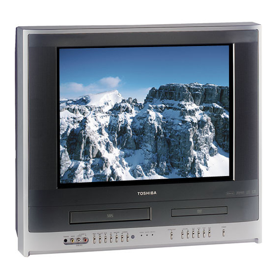
SERVICE MANUAL
COMBINATION FLAT COLOR
TELEVISION AND VIDEO
CASSETTE RECORDER/
DVD VIDEO PLAYER
The above model is classified as a green product (*1), as indicated by the underlined serial number.
This Service Manual describes replacement parts for the green product. When repairing this green
product, use the part(s) described in this manual and lead-free solder (*2).
For (*1) and (*2), see the next page.
©2007 Toshiba Corporation
MW24H63
DOCUMENT CREATED IN JAPAN, March, 2007 GREEN
FILE NO. 810-200710GR
REVISED: 01
Advertisement
Table of Contents
Troubleshooting

Related Manuals for Toshiba MW27H63


Summary of Contents for Toshiba MW27H63
- Page 1 This Service Manual describes replacement parts for the green product. When repairing this green product, use the part(s) described in this manual and lead-free solder (*2). For (*1) and (*2), see the next page. ©2007 Toshiba Corporation DOCUMENT CREATED IN JAPAN, March, 2007 GREEN...
-
Page 2: Green Product Procurement
Hazardous Substances. From July 1, 2006, the RoHS Directive will prohibit any marketing of new products containing the restricted substances. Increasing attention is given to issues related to the global environmental. Toshiba Corporation recognizes environmental protection as a key management tasks, and is doing its utmost to enhance and improve the quality and scope of its environmental activities. -
Page 3: Owner's Manual
The model number and serial number are on the back of your TV. Record ColorStream, FST Pure and StableSound are registered trademarks of Toshiba America Consumer Products, L.L.C. these numbers in the spaces below. Refer to these numbers whenever you... - Page 4 Antenna lead-in wire Antenna discharge unit (NEC Section 810-20) Ground clamp Grounding conductors (NEC Section 810-21) Electric service equipment Power service grounding electrode system (NEC Art 250 Part H) Ground clamp QUALIFIED SERVICE TECHNICIAN 0303 Tape Head drum Wall outlet...
- Page 5 DIGITAL VIDEO ¿ DVD button POWER button TV/VCR button SLEEP button 24 Direct channel Selection buttons (0-9) Number buttons (0-9) DISPLAY button CM SKIP button button JUMP button buttons VOL +/- buttons ZERO RETURN button AUDIO SELECT button 37 58 SUBTITLE button MUTE button INPUT button...
- Page 6 ¿ VIDEO1 Analog channel Digital channel VIDEO1 S O U RC E S E L E CT I O N (Back) 0 . A N A LO G 1 . D I G I TA L 2 . V I D E O 1 ColorStream VIDEO2 3 .
- Page 7 CH PROGRAM L A N G UAG E / ANALOG CH SEARCH LANGUAGE/IDIOMA/LANGUE I D I O M A / L A N G U E STOP : CANCEL C LO C K S E T ENGLISH AU TO C LO C K ESPAÑOL STA N DA R D T I M E FRANÇAIS...
- Page 8 C LO C K S E T M O N T H 3 1 ( S AT ) L A N G UAG E / Y E A R 2 0 0 7 L A N G UAG E / I D I O M A / L A N G U E T I M E I D I O M A / L A N G U E...
- Page 9 A D D / E R AS E SA P O F F C LO S E D CA P T I O N V- C H I P C H 0 1 2 AU TO S H U T O F F O F F / M E N U S L E E P...
- Page 10 A D D / E R AS E SA P O F F C LO S E D CA P T I O N V- C H I P V- C H I P AU TO S H U T O F F O F F V- C H I P O F F...
- Page 11 O N / O F F T I M E R O N T I M E R O N / O F F T I M E R 1 2 : 0 0 A M O N T I M E R D I G I TA L C H 5 1 - 0 0 1 : 0 0 A M...
- Page 12 BAS S A D D / E R AS E T R E B L E SA P O F F C H 0 1 3 BA L A N C E C LO S E D CA P T I O N ST E R E O SA P STA B L E S O U N D O F F...
- Page 13 CASSETTE PLAY LOADING SLOT STOP/EJECT TV/VCR 8 : 40AM THU CH 012 T I M E R R E C S E T AU TO R E P E AT O F F 00 : 30 : 50 SP / M E N U M A N UA L T R AC K D I G I TA L T R AC K TV/VCR...
- Page 14 TV/VCR 8 : 40AM THU CH 012 00 : 30 : 50 SP 00 : 00 : 00 SP TV/VCR 8 : 40AM THU CH 012 00 : 00 : 00 SP CH 110 REC/OTR CH 110 TV/VCR 9 : 00AM THU CH 012 00 : 20 : 00 SP REC/OTR...
- Page 15 O N / O F F T I M E R T I M E R R E C S E T 2 3 T H U 7 : 0 0 PM 9 : 3 0 PM 25-001 SLP O N T I M E R –...
- Page 16 Jump Title Chapter Time Play Mode Repeat : Off Jump Title Chapter Time Jump Play Mode Title Mode : Off – – – Chapter Repeat : Off – – – Time – – – Program Playback...
- Page 17 Play Mode Mode – – – Repeat : Off – – – – – – Program Playback Play Mode Play Mode Mode : Program Mode : Program – – – Repeat : Off Repeat : Off – – – Program Playback –...
- Page 18 /MP3-2.MP3 Folder-1 Select Files Folder-2 Repeat :Off MP3-1 Mode :Off MP3-2 MP3-3 WMA-1 JPEG Preview WMA-2 WMA-3 Operation status File number Elapsed time Selected file name 1/15 00:00:00 /MP3-5.MP3 MP3-5 Select Files MP3-6 Repeat :Off Tool kit WMA-11 Mode :Off window File list WMA-12...
- Page 19 Folder-1 Edit Mode Folder-1 Select Files Folder-1 Select Files Folder-1 Repeat :Off Folder-2 Program View Folder-2 Repeat :Off Folder-2 Repeat :Off Folder-2 Mode :Off MP3-1 Add To Program MP3-1 Mode :Off MP3-1 Mode :Off MP3-1 Edit Mode MP3-2 MP3-2 MP3-2 MP3-2 MP3-3 MP3-3...
- Page 20 Menu : English TV Screen : 4:3 : Off Subtitle : English Display : On Audio : English Picture Mode : Auto JPEG Interval : Off Parental : Off Password : Change DivX(R) VOD : Display Enter Password...
- Page 22 ¿ [continued on next page]...
-
Page 23: Caution
CAUTION THIS DIGITAL VIDEO PLAYER EMPLOYS A LASER SYSTEM. TO ENSURE PROPER USE OF THIS PRODUCT, PLEASE READ THIS SERVICE MANUAL CARE- FULLY AND RETAIN FOR FUTURE REFERENCE. SHOULD THE UNIT REQUIRE MAINTENANCE, CONTACT AN AUTHORIZED SERVICE LOCATION-SEE SERVICE PROCEDURE. USE OF CONTROLS, ADJUSTMENTS OR THE PERFORMANCE OF PROCEDURES OTHER THAN THOSE SPECIFIED HEREIN MAY RESULT IN HAZARDOUS RADIATION EXPOSURE. -
Page 24: How To Order Parts
SERVICING NOTICES ON CHECKING 1. KEEP THE NOTICES 6. AVOID AN X-RAY As for the places which need special attentions, Safety is secured against an X-ray by consider- they are indicated with the labels or seals on the ing about the cathode-ray tube and the high cabinet, chassis and parts. -
Page 25: Important Safeguards
IMPORTANT SAFEGUARDS READ INSTRUCTIONS All the safety and operating instructions should be read before the unit is operated. RETAIN INSTRUCTIONS The safety and operating instructions should be retained for future reference. HEED WARNINGS All warnings on the unit and in the operating instructions should be adhered to. FOLLOW INSTRUCTIONS All operating and use instructions should be followed. - Page 26 IMPORTANT SAFEGUARDS (CONTINUED) OUTDOOR ANTENNA GROUNDING If an outside antenna or cable system is connected to the unit, be sure the antenna or cable system is grounded so as to provide some protection against voltage surges and built-up static charges. Section 810 of the National Electrical Code, ANSI/NFPA 70, provides information with respect to proper grounding of the mast and supporting structure, grounding of the lead-in wire to an antenna discharge unit, size of grounding conductors, location of antenna discharge unit, connection to grounding electrodes, and requirements for the grounding electrode.
- Page 27 IMPORTANT SAFEGUARDS (CONTINUED) EXAMPLE OF ANTENNA GROUNDING AS PER THE NATIONAL ELECTRICAL CODE ANTENNA LEAD IN WIRE GROUND CLAMP ANTENNA DISCHARGE UNIT (NEC SECTION 810-20) ELECTRIC SERVICE EQUIPMENT GROUNDING CONDUCTORS (NEC SECTION 810-21) GROUND CLAMPS POWER SERVICE GROUNDING NEC-NATIONAL ELECTRICAL CODE ELECTRODE SYSTEM (NEC ART 250, PART H) S2898A...
-
Page 28: When Replacing Dvd Deck
WHEN REPLACING DVD DECK [ Removing the DVD Deck ] Before removing Pick Up PCB and DVD MT PCB connector,short circuit the position shown in Fig. 1 using a soldering iron. If you remove the DVD Deck with no soldering, the Laser may be damaged. [ Installing the DVD Deck ] Remove all the soldering on the short circuit position after the connection of Pick Up PCB and DVD PCB connector. -
Page 29: Tape Removal Method At No Power Supply
TAPE REMOVAL METHOD AT NO POWER SUPPLY Remove the TV/DVD/VCR block from the main unit as shown in Fig. 1 below. (Refer to item 1 of the DISASSEMBLY INSTRUCTIONS.) Remove one screw of the Loading Motor from the insert hole for screw driver and remove the Loading Motor. -
Page 30: Parental Control - Rating Level
PARENTAL CONTROL - RATING LEVEL 4 DIGIT PASSWORD CANCELLATION If the stored 4 digit password in the Rating Level menu needs to be cancelled, please follow the steps below. Turn Unit ON. Set the DVD to the Stop Mode. Check that 'No disc' is displayed on the screen. Press and hold the 'STOP' button on the front panel. -
Page 31: Table Of Contents
TABLE OF CONTENTS • GREEN PRODUCT PROCUREMENT • LEAD-FREE SOLDER • OWNER'S MANUAL A1-1 CAUTION ....................................A1-2 SERVICE NOTICES ON CHECKING............................. A1-2 HOW TO ORDER PARTS..............................A1-3~A1-5 IMPORTANT SAFEGUARDS..............................A1-6 WHEN REPLACING DVD DECK .............................. A1-7 TAPE REMOVAL METHOD AT NO POWER SUPPLY ......................A1-7 DISC REMOVAL METHOD AT NO POWER SUPPLY ...................... -
Page 32: General Specifications
GENERAL SPECIFICATIONS CRT Size / Visual Size 24 inch / 600.0mmV System CRT Type Flat Magnetic Field BV/BH +0.45G / 0.18G Color System NTSC Speaker 2 Speaker Position Front Side Size 1.8 x 3.9 Inch Impedance 8 ohm Sound Output 2.5W + 2.5W 10%(Typical) System... - Page 33 GENERAL SPECIFICATIONS Signal Video Signal Input Level 1 V p-p/75 ohm Output Level S/N Ratio (Weighted) at DVD Mode S/N Ratio (Weighted) at VCR Mode Horizontal Resolution at DVD Mode Horizontal Resolution at VCR(SP)Mode RGB Signal Output Level Audio Signal Input Level -8.0dBm/50k ohm Output Level(0dB=0.775Vrms)
- Page 34 GENERAL SPECIFICATIONS G-12 Remote Unit RC-KH Control Glow in Dark Remocon Unit Remocon Format TOSHIBA Format TOSHIBA Custom Code 40-BFh, 44-BBh, 45-BAh Power Source Voltage(D.C) UM size x pcs UM-4 x 2 pcs Total Keys Keys TV/VCR Power Channel- Channel+...
- Page 35 GENERAL SPECIFICATIONS G-13 Features Auto Head Cleaning (TV/VCR) VIDEO PLUS+(SHOWVIEW,G-CODE) Forward / Reverse Picture Search Index Search SQPB CM Skip(30sec x 6 Times) Zero Return End Call TV Monitor Program Extend Picture Brightness , Contrast , Color, Sharpness Tint Mode (Picture Preference) Color Temperature CableClear Cinema Mode...
- Page 36 GENERAL SPECIFICATIONS Features Tray Lock (DVD) Auto Stop (Pause, and Resume Stop after 5min.) (Some USB devices may not be usable.) Card Slot Reading (Not secured Data) Video CD Playback SVCD Playback MP3 Playback WMA Playback JPEG Playback DivX Play back DMF Support Digital Out (Dolby Digital)
- Page 37 Height (cm) Container Stuffing(40' container) Sets w/Pallet w/Wrapping G-19 Material Cabinet Front 94V0 DECABROM Rear 94V0 DECABROM Jack Panel Non-Halogen Demand Eyelet Demand G-20 Environment Environmental standard requirement (by buyer) Green procurement of TOSHIBA Pb-free Phase3(Phase3A) Measures for Whisker A3-6...
-
Page 38: Disassembly Instructions
DISASSEMBLY INSTRUCTIONS 1. REMOVAL OF MECHANICAL PARTS 1-3: TV/DVD/VCR BLOCK (Refer to Fig. 1-3) AND P.C. BOARDS Remove the 2 screws (1). Disconnect the following connectors: 1-1: BACK CABINET (Refer to Fig. 1-1) (CP353, CP404 and CP1704). Remove the 6 screws (1). Remove the TV/DVD/VCR Block in the direction of arrow. - Page 39 DISASSEMBLY INSTRUCTIONS 1-5: VCR MT PCB (Refer to Fig. 1-5) 1-7: DVD MT PCB/DVD DECK (Refer to Fig. 1-7) Remove the 7 screws (1). Short circuit the position shown in Fig. 1-7 using a Remove the screw (2). soldering iron. If you remove the DVD Deck with no Remove the AV Jack Shield.
- Page 40 DISASSEMBLY INSTRUCTIONS 1-8: DEFLECTION PCB (Refer to Fig. 1-8) Remove the 2 screws (1). Remove the 3 screws (2). Remove the Deflection PCB in the direction of arrow. (1) (1) Deflection PCB Bottom Plate Fig. 1-8 B1-3...
-
Page 41: Removal Of Vcr Deck Parts
DISASSEMBLY INSTRUCTIONS 2. REMOVAL OF VCR DECK PARTS 2-3: LINK UNIT (Refer to Fig. 2-3) Set the Link Unit to the Eject position. 2-1: TOP BRACKET (Refer to Fig. 2-1) Unlock the support (1). Extend the 2 supports (1). Remove the (A) side of the Link Unit first, then remove Slide the 2 supports (2) and remove the Top Bracket. - Page 42 DISASSEMBLY INSTRUCTIONS 2-5: LOADING MOTOR/WORM (Refer to Fig. 2-5-A) 2-6: TENSION ASS'Y (Refer to Fig. 2-6-B) Remove the screw (1). Turn the Pinch Roller Cam clockwise so that the Tension Remove the Loading Motor. Holder hook is set to the position of Fig. 2-6-A to move the Remove the Worm.
- Page 43 DISASSEMBLY INSTRUCTIONS NOTE [OK] Tension Connect Take care not to damage the gears of the S Reel and T Reel. Tension Band The Polyslider Washer may on the back of the reel. Take care not to damage the shaft. [NG] Tension Connect Tension Band Do not touch section "A"...
- Page 44 DISASSEMBLY INSTRUCTIONS 2-9: CASSETTE OPENER/PINCH ROLLER BLOCK/P5 ARM ASS'Y (Refer to Fig. 2-9-A) Unlock the support (1) and remove the Cassette Opener. Remove the Pinch Roller Block and P5 Arm Ass'y. Cassette Opener Spring Position Fig. 2-10-B Pinch Roller Block 2-11: FE HEAD (RECORDER ONLY) (Refer to Fig.
- Page 45 DISASSEMBLY INSTRUCTIONS 2-13: CAPSTAN DD UNIT (Refer to Fig. 2-13) NOTE 1. In case of the Pinch Roller Cam and Main Cam installa- Remove the Capstan Belt. tion, install them as shown in the circled section of Fig. 2- Remove the screw (1). 14-B so that the markers meet.
- Page 46 DISASSEMBLY INSTRUCTIONS NOTE 2-17: CASSETTE GUIDE POST/INCLINED BASE S/T UNIT/P4 CAP/LED REFLECTOR 1. When you install the Loading Arm S Unit, Loading Arm T (Refer to Fig. 2-17-A) Unit and Main Loading Gear, align each marker. (Refer to Fig. 2-15-B) Remove the P4 Cap.
-
Page 47: Removal Of Dvd Deck Parts
DISASSEMBLY INSTRUCTIONS 3-2: MAIN CHASSIS ASS'Y (Refer to Fig. 3-2-A) 3. REMOVAL OF DVD DECK PARTS Remove the screw (1). NOTE Unlock the 2 supports (2). 1. Disassemble only the DVD DECK PARTS parts listed Remove the Insulator (R) from the Main Frame Ass'y. here. - Page 48 DISASSEMBLY INSTRUCTIONS 3-3: LOADING MOTOR PCB ASS'Y/ LOADING BELT 3-4: RACK LOADING/MAIN GEAR/PULLEY GEAR (Refer to Fig. 3-3-A) (Refer to Fig. 3-4-A) Remove the Loading Belt. Press down the catcher (1) and slide the Rack Loading. Remove the screw (1). Unlock the support (2) and remove the Pulley Gear.
- Page 49 DISASSEMBLY INSTRUCTIONS Switch PCB Ass'y Clamper Plate Middle Gear Clamper No gap Fig. 3-5-B 3-6: TRAVERSE HOLDER/INSULATOR (F)/INSULATOR Motor Gear (R) (Refer to Fig. 3-6-A) Main Chassis Ass'y Remove the Traverse Holder. Feed Motor • Screw Torque: 3.0 ± 0.3kgf•cm (Screw (1)) Remove the 2 Insulator (F).
- Page 50 DISASSEMBLY INSTRUCTIONS 3-8: FFC WIRE HANDLING When installing the FFC, fold it correctly and install it as shown from Fig. 3-8-A to Fig. 3-8-C. NOTE Do not make the folding lines except the specified positions for the FFC. [ 24 pin FFC ] Fold back at the border line of the reinforcement plate.
-
Page 51: Removal Of Anode Cap
DISASSEMBLY INSTRUCTIONS 4. REMOVAL OF ANODE CAP 3. After one side is removed, pull in the opposite direction to remove the other. Read the following NOTED items before starting work. NOTE After turning the power off there might still be a potential Take care not to damage the Rubber Cap. -
Page 52: Removal And Installation Of Flat Package Ic
DISASSEMBLY INSTRUCTIONS 5. REMOVAL AND INSTALLATION OF FLAT 3. When IC starts moving back and forth easily after desoldering completely, pickup the corner of the IC using PACKAGE IC a tweezers and remove the IC by moving with the IC REMOVAL desoldering machine. - Page 53 DISASSEMBLY INSTRUCTIONS INSTALLATION 4. When bridge-soldering between terminals and/or the soldering amount are not enough, resolder using a Thin- 1. Take care of the polarity of new IC and then install the tip Soldering Iron. (Refer to Fig. 5-8.) new IC fitting on the printed circuit pattern. Then solder each lead on the diagonal positions of IC temporarily.
-
Page 54: Key To Abbreviations
KEY TO ABBREVIATIONS Audio/Control H.SW Head Switch Automatic Color Control Hertz Audio Erase Integrated Circuit Automatic Frequency Control Intermediate Frequency Automatic Fine Tuning Indicator AFT DET Automatic Fine Tuning Detect Inverter Automatic Gain Control Killer Amplifier Left Antenna Light Emitting Diode A.PB Audio Playback LIMIT AMP... - Page 55 KEY TO ABBREVIATIONS SYNC Synchronization SYNC SEP Sync Separator, Separation Transistor TRAC Tracking TRICK PB Trick Playback Test Point UNREG Unregulated Volt Voltage Controlled Oscillator Video Intermediate Frequency Vertical Pulse, Voltage Display V.PB Video Playback Variable Resistor V.REC Video Recording Visual Search Fast Forward Visual Search Rewind Voltage Super Source...
-
Page 56: Service Mode List
SERVICE MODE LIST This unit is provided with the following SERVICE MODES so you can repair, examine and adjust easily. To enter to the SERVICE MODE function, press and hold both buttons simultaneously on the main unit and on the remote control for more than the standard time in the appropriate condition. -
Page 57: Preventive Checks And Service Intervals
PREVENTIVE CHECKS AND SERVICE INTERVALS The following standard table depends on environmental conditions and usage. Parts replacing time does not mean the life span for individual parts. Also, long term storage or misuse may cause transformation and aging of rubber parts. The following list means standard hours, so the checking hours depends on the conditions. - Page 58 PREVENTIVE CHECKS AND SERVICE INTERVALS 2. TAPE RUNNING SYSTEM CLEANING When cleaning the tape transport system, use gauze NOTE moistened with isopropyl alcohol. After cleaning the heads with isopropyl alcohol, do not 3. CYLINDER run a tape until the heads dry completely. If the heads are not completely dry and alcohol gets on the tape, Wrap a piece of chamois around your finger.
-
Page 59: Re-Write For Dvd Firmware
RE-WRITE FOR DVD FIRMWARE Turn on the power, and set the DVD mode. Press both VOL. DOWN button on the set and Channel button (0) on the remote control for more than 2 seconds. Press VOL. UP/DOWN button on the unit to check if all the keys on the unit do not function. NOTE: To check if DVD Write mode is set. -
Page 60: Re-Write For Digital Soft Firmware
RE-WRITE FOR DIGITAL SOFT FIRMWARE Confirm that the AC cord is plugged out. Using the Serial Communication Change JIG (JG205), connect the set to personal computer. (Refer to Fig. 1) NOTE: It is possible to write only with the personal computer of WINDOWS. Fig. - Page 61 WHEN REPLACING EEPROM (MEMORY) IC If a service repair is undertaken where it has been required to change the MEMORY IC, the following steps should be taken to ensure correct data settings while making reference to TABLE 1. +9 +A +B +C +D +E +F +0 +1 INIT 57 00...
-
Page 62: Servicing Fixtures And Tools
SERVICING FIXTURES AND TOOLS Torque cassette gauge Alignment Tape Back tension cassette gauge Taper nut driver (KT-300NR) ST-N5 ST-NF 70909103 70909199 70909228 VTR cleaning kit VTR lubrication kit Grease JG002B Adapter JG002E Dial Torque Gauge (10~90gf•cm) JG002F (60~600gf•cm) JG022 Master Plane JG024A Reel Disk Height JG153 X Value Adjustment JG154 Cable... -
Page 63: Preparation For Servicing
PREPARATION FOR SERVICING How to use the Servicing Fixture While pressing the CH DOWN button on the set for more than 2 seconds, press the ON/STANDBY button on the set simultaneously at the Power OFF. Although the DVD is connected, the DVD mode cannot be selected. Short circuit between TP1001 and Ground with the cable JG154. -
Page 64: Mechanical Adjustments
MECHANICAL ADJUSTMENTS 1. CONFIRMATION AND ADJUSTMENT 1-2: CONFIRMATION AND ADJUSTMENT OF TENSION POST POSITION Read the following NOTES before starting work. Set to the PLAY mode. • Place an object which weighs between 450g~500g on the Adjust the adjusting section for the Tension Arm position Cassette Tape to keep it steady when you want to make so that the Tension Arm top is within the standard line of the tape run without the Cassette Holder. - Page 65 MECHANICAL ADJUSTMENTS 1-4: CONFIRMATION OF VSR TORQUE NOTE Install the Torque Gauge (JG002F) and Adapter (JG002B) If the torque is out of the range, replace the following parts. on the S Reel. Set to the Picture Search (Rewind) mode. Replacement Part Check item (Refer to Fig.1-4-B) Then, confirm that it indicates 120~180gf•cm.
- Page 66 MECHANICAL ADJUSTMENTS 2-3: TAPE RUNNING ADJUSTMENT 2-2: CONFIRMATION AND ADJUSTMENT OF AUDIO/ (X VALUE ADJUSTMENT) CONTROL HEAD Confirm and adjust the height of the Reel Disk. When the Tape Running Mechanism does not work well, (Refer to item 1-1) adjust the following items. Confirm and adjust the position of the Tension Post.
- Page 67 MECHANICAL ADJUSTMENTS 3. MECHANISM ADJUSTMENT PARTS LOCATION GUIDE 1. Tension Connect P4 Post 2. Tension Arm T Brake Spring 3. Guide Roller T Reel 4. Audio/Control Head S Reel 5. X value adjustment driver hole Adjusting section for the Tension Arm position D2-4...
-
Page 68: Electrical Adjustments
ELECTRICAL ADJUSTMENTS BEFORE MAKING ELECTRICAL FUNCTION FUNCTION OSD H BRI MIN ADJUSTMENTS OSD C CONT CENT CUT OFF CONT MAX Read and perform these adjustments when repairing the H.POSI CONT MIN circuits or replacing electrical parts or PCB assemblies. H.BLK L COL CENT H.BLK R COL MAX... - Page 69 ELECTRICAL ADJUSTMENTS (TV SECTION) TV-A 2-2: CONSTANT VOLTAGE Place the set in AV MODE without signal. Using the remote control, set the brightness and contrast to normal position. Connect the digital voltmeter to TP401. Adjust the VR1701 until the digital voltmeter is 115 ± 0.5V. 00 OSD H 2-3: CUT OFF Adjust the unit to the following settings.
- Page 70 ELECTRICAL ADJUSTMENTS 2-10: VERTICAL LINEARITY White 0% NOTE: Adjust after performing adjustments in section 2-9. After the adjustment of Vertical Linearity, reconfirm the Vertical Position and Vertical Size adjustments. Receive the monoscope pattern. Using the remote control, set the brightness and 100% contrast to normal position.
- Page 71 ELECTRICAL ADJUSTMENTS 2-13: BRIGHT CENTER 2-14: CONTRAST MAX Receive the monoscope pattern. (RF Input) Receive the monoscope pattern. (RF Input) Using the remote control, set the brightness and contrast Using the remote control, set the brightness and contrast to normal position. to normal position.
- Page 72 ELECTRICAL ADJUSTMENTS 2-20: Confirmation of Fixed Value (step No.) 2-16: PARABOLA Receive the crosshatch signal from the Pattern Please check if the fixed values of the each adjustment Generator. item is set correctly referring below. Using the remote control, set the brightness and ANALOG DIGITAL VIDEO1, VIDEO2...
- Page 73 ELECTRICAL ADJUSTMENTS 3-3: STATIC CONVERGENCE 3. PURITY AND CONVERGENCE ADJUSTMENTS NOTE Adjust after performing adjustments in section 3-2. NOTE Receive the crosshatch pattern from the color bar Turn the unit on and let it warm up for at least 30 generator.
- Page 74 ELECTRICAL ADJUSTMENTS 4. ELECTRICAL ADJUSTMENT PARTS LOCATION GUIDE (WIRING CONNECTION) DEFLECTION PCB CD1702 AC IN VCR DECK TP401 FB401 CD807 CD1704 DVD DECK CD808 CD1703 CP1704 CP604 CP404 CD604 CP003 VCR DECK CP004 CD852 CP1702 CD1705 VR404 CP001 CP602 CP301 CD301 VR1701 CP4502...
-
Page 75: Troubleshooting Guide
TROUBLESHOOTING GUIDE (TV SECTION) POWER DOES NOT TURN ON (1) When turning on the Check pins 27 and 30 of IC1001 power switch, does the and peripheral circuit. LED light ? Is CD602 inserted ? Insert CD602. Check Q401, Q403 and Does Q401 and Q403 work ? peripheral circuit. -
Page 76: Troubleshooting Guide
TROUBLESHOOTING GUIDE NO PICTURE Are the Brightness and Adjust Brightness and Contrast. Contrast set to normal ? Is the voltage at pin 1 Check P.CON + 8V line. of CD603 DC8V ? Is the signal at pins 14, 15 Is the waveform at pins 3 Check Y OUT and c OUT line. - Page 77 TROUBLESHOOTING GUIDE NO COLOR Adjust the color. Is the color set to normal ? Receive the color signal. Is the color signal received ? Is the waveform at pin Check X601 and peripheral circuit. 35 of IC601 normal ? Check IC601 and peripheral circuit. ONLY A LINE APPEARS Is the voltage at pins 2 Check FB401 peripheral circuit.
- Page 78 TROUBLESHOOTING GUIDE OSD SCREEN DOES NOT APPEAR Check IC1001 and the peripheral Is there a waveform at pins circuit. 60, 62, 63 and 64 of IC1001 ? Is there a waveform at Check pins 14, 15 and 16 of pins 54, 55, 56 and 57 of IC601 and the peripheral circuit.
-
Page 79: Vcr Section
TROUBLESHOOTING GUIDE (VCR SECTION) PLAYBACK CHANGES TO STOP Insert a cassette and press PLAY button. Does Playback change to Check TAPE LOADING, CAPSTAN Stop about 3 seconds later? DD UNIT and CYLINDER UNIT. Check Q1001, Q1005 and Does Playback change to Stop about 6 seconds later? CAPSTAN BELT. - Page 80 TROUBLESHOOTING GUIDE NO PLAYBACK PICTURE Is the voltage at pins Does E-E appear on Check Power circuit. 23, 45, 52, 68 and 77 the Monitor TV ? of IC4501 5V ? Is there Y/C signal at pin Replace IC4501. 26 of IC4501 ? Check IC601 and peripheral circuit.
- Page 81 TROUBLESHOOTING GUIDE PLAYBACK PICTURE IS NOISY (EVEN AFTER CLEANING HEADS) Check HEAD AMP and interchange Is FM signal at TP4501 adjustments. more than 200mVp-p ? Is FM signal at pins 72 Check CP4501 and peripheral circuit. and 73 of IC4501 ? Is VIDEO waveform at Replace IC4501.
- Page 82 TROUBLESHOOTING GUIDE NO COLOR DURING SELF RECORDING AND PLAYBACK Does VIDEO signal Check J2202 and VIDEO input appear at pins 28, 30 circuit. and 32 of IC4501 ? Is FM signal at pin 73 Replace IC4501. of IC4501 ? Replace CYLINDER UNIT. NO NORMAL AUDIO IN PLAYBACK MODE Refer to section "NO E-E".
- Page 83 TROUBLESHOOTING GUIDE CAPSTAN DD MOTOR NOT ROTATING In playback, is the Check POWER circuit. voltage at pin 2 of CP1001 DC 12V ? Is the voltage at pin 3 of CP1001 DC 5V ? In playback, is the voltage Replace IC1001. at pin 12 of IC1001 3.6V ? Replace IC1001 and DD MOTOR.
- Page 84 TROUBLESHOOTING GUIDE AUDIO CAN NOT BE RECORDED Is the voltage at pin 68 Check POWER BLOCK. Is BIAS waveform appeared ? of IC4501 5V ? L4502 is broken or shorted. Check peripheral circuit. Is there AUDIO signal at Check the circuit between audio pins 76, 78 and 80 of out of Tuner and IC4501.
- Page 85 TROUBLESHOOTING GUIDE RECORDING MECHANISM WORKS, BUT NO VIDEO AND AUDIO RECORDED FROM INPUT JACK OR TUNER Does AUDIO signal Check the circuit from AUDIO input jack to IC4501 and from Tuner Pack appear at pins 76, 78 to IC4501. and 80 of IC4501 ? Is there FM signal at Replace IC4501.
- Page 86 TROUBLESHOOTING GUIDE CYLINDER NOT ROTATING DURING PLAYBACK AND RECORDING Check MOTER +12V line and Is the voltage at pin 8 of POWER BLOCK. CP1001 about DC12V ? In playback, is the voltage at pin 12 of Check IC1001. CP1001 about DC3.6V ? Replace CYLINDER UNIT.
- Page 87 TROUBLESHOOTING GUIDE CASSETTE TAPE IS NOT ACCEPTED Does WORM GEAR Check FRONT LOADING GEARS. on FRONT LOADING UNIT activate ? When cassette is not Check Photo sensor. inserted, is the voltage at pin 4 of IC1001 5V ? When cassette is not inserted, is the voltage at Replace IC1001.
- Page 88 TROUBLESHOOTING GUIDE WHEN INSERTING CASSETTE, IT EJECTS IMMEDIATELY Does this same problem Defective CASSETTE or FRONT appear when using LOADING UNIT. another cassette tape ? When inserting a Replace EOT PHOTO cassette, does Emitter of TRANSISTORS. EOT return to LOW ? Check IC 1001 circuit.
- Page 89 TROUBLESHOOTING GUIDE TAPE LOADING IS OK, BUT UNLOADS IMMEDIATELY Is the voltage at pins 2 Does CYLINDER rotate ? Check Power circuit. and 8 of CP1001, unregulated at 12V ? In playback, is the Does pin 76 of IC1001 feed voltage at pin 12 of DC5V PULSE ? CP1001 3.6V ?
- Page 90 TROUBLESHOOTING GUIDE PLAYBACK PICTURE JITTERS VERTICALLY. Does tracking noise appear in the picture ? By adjusting the manual tracking UP/DOWN buttons, Check P/B ENVELOPE. will the noise disappear in the picture ? Are GUIDE POSTS Adjust GUIDE POST height. the right height ? Is PG SHIFTER Adjust PG SHIFTER.
- Page 91 TROUBLESHOOTING GUIDE PLAYBACK PICTURE JITTERS HORIZONTALLY Is FG output level at pin Replace CYLINDER UNIT. 11 of CP1001 5Vp-p ? Is the voltage at pin 12 Replace IC1001. of CP1001 3.6V ? Replace CYLINDER UNIT. AUTO TRACKING DOES NOT OPERATE By manual tracking, does CYLINDER UNIT.
- Page 92 TROUBLESHOOTING GUIDE WHEN PLAYBACK, FAST FORWARD OR REWIND MODE IS ACTIVATED, UNIT STOPS IMMEDIATELY Refer to section "CAPSTAN DD Does CAPSTAN DD MOTOR NOT ROTATING". MOTOR rotate ? Is CAPSTAN BELT Replace CAPSTAN BELT. normal? Does REEL SENSOR Check Reel Sensor of Q1001 and PULSE signal appear at R1019.
-
Page 93: Dvd Section
TROUBLESHOOTING GUIDE (DVD SECTION) DECK DOES NOT ACCEPT OPEN/CLOSE Is the voltage at pins 3, 18 Check P.CON+6V line of POWER and 19 of IC2301 about BLOCK. DC6V ? Is the lose connection at Check CP2302 connection to DECK. CP2302 to DECK ? Change DVD LOADER. - Page 94 TROUBLESHOOTING GUIDE DVD NO PICTURE Is CP8101 connected ? Connect CP8101. Is there input signal at pins Check IC601. 1, 3 and 5 of CP8101 ? Does X4001 oscillation ? Change X4001. Change IC4001. E-20...
- Page 95 TROUBLESHOOTING GUIDE DVD, CD NO PLAY ("BLUE BACK LOGO" SHOW ON SCREEN.) After reading,check When play, check the Change DVD DECK. "INCORRECT DISC" DECK MOTOR moving ? display ? Change DVD DECK. Is CD2301 connected ? Connect CD2301. Is CP2301 connected ? Connect CP2301.
- Page 96 TROUBLESHOOTING GUIDE INSTABILITY DVD MODE Connect CD8101. Is CD8101 connected ? Does connector of Change DVD DECK. DVD DECK do short 0? Is CD2001 and CD2301 Connect CD2001 and CD2301. connected ? Change DVD DECK. E-22...
-
Page 97: Mechanical Exploded View
MECHANICAL EXPLODED VIEW 102B 102B 102A PCB110 (CRT PCB ASS'Y) 102B 101N 101D 101N 101C 101N 101M 101L 101J 101H 101F 101N 101K 101B 101E 101H 101K 101I 101G 101O 101A J1-1... - Page 98 MECHANICAL EXPLODED VIEW PCBDH0 (DIGITAL PCB ASS'Y) PCB130 (DVD MT PCB ASS'Y) PCB010 (VCR MT PCB ASS'Y) PCB270 (OPERATION PCB ASS'Y) PCB080 (DEFLECTION PCB ASS'Y) J1-2...
- Page 99 MECHANICAL EXPLODED VIEW (PACKING DIAGRAM) 146, 147, 148, 149, 150, 151 TM101 J1-3...
-
Page 100: Chassis Exploded View
CHASSIS EXPLODED VIEW (TOP VIEW) CD1501 M2003 UN4001 H5002 H5001 CD1502 M101 NOTE: Applying positions AA for the grease are displayed for this section. CLASS MARK Check if the correct grease is applied for each position. GREASE J2-1... - Page 101 CHASSIS EXPLODED VIEW (BOTTOM VIEW) M2001 CD1501 CD1502 NOTE: Applying positions AA for the grease are displayed for this section. CLASS MARK Check if the correct grease is applied for each position. GREASE J2-2...
-
Page 102: Dvd Deck Exploded View
DVD DECK EXPLODED VIEW Cannot supply separately. If the repair is needed, replace the LOADER SUB ASS'Y. M2603 PCB610 CD2301 (LOADING MOTOR PCB ASS'Y) CD2302 PCB640 CD2001 (SW PCB ASS'Y) Do not replace the parts. Because, minute adjustments are needed if this condition is disassembled further more. -
Page 103: Mechanical Replacement Parts List
MECHANICAL REPLACEMENT PARTS LIST Location No. TSB P/N Reference No. Description 75006480 7A701A870A FRONT CABI ASS'Y 101A 75006481 701WPJD418 CABINET FRONT 101B 75002712 711WPA0275 PLATE FRONT 101C 75006482 712WPJC313 FLAT FLAP 101D 75006483 712WPJC314 FLAP DVD 101E 72798520 713WPA0311 GLASS,LED 101F 72798521 713WPA0312 GUIDE,REMOCON... - Page 104 MECHANICAL REPLACEMENT PARTS LIST Location No. TSB P/N Reference No. Description 75002750 JB5ND500 POLYBAG INSTRUCTION(RED CAUTION) 72781569 J3N51617A REGISTRATION CARD 72781605 J5S10229A INFORMATION SHEET(RETURN)USA 75006295 J5V60128B WARNING SHEET 75006296 J5Y40101A INSTRUCTION BOOK 75006297 J5Y40107A QUICK SET-UP SHEET 72781978 8965TS1017 CUSHION 65TS10-10(17.5*20*14) 72798796 8141H60C5U SCREW,TAP TITE(P) GW20 6*35 CH HEXAGO...
-
Page 105: Chassis Replacement Parts List
CHASSIS REPLACEMENT PARTS LIST Location No. TSB P/N Reference No. Description 72783455 A5T410J420A DECK ASSY A5T410J420A 72795710 85OA400245 PINCH ROLLER BLOCK VA2 72795711 85OA500026 AHC ASS'Y 72795712 85OP200290 BELT,CAPSTAN (S) 72795713 85OP600581 WORM 72795714 85OP500091 BASE,AC HEAD 72795715 85OP800324 SPRING,AC HEAD 72795716 85OA000528 MAIN CHASSIS ASS'Y... -
Page 106: Dvd Deck Replacement Parts List
DVD DECK REPLACEMENT PARTS LIST Location No.TSB P/N Reference No. Description ! 600 75006298 A2J901T650 DVD MECHA ASS'Y A2J901T650 72795767 92P100109A HOLDER,TRAVERSE 72795768 92P100094A CLAMPER 72795769 92P100088A GEAR,MOTOR 75006299 92P100108B GEAR,MIDDLE 72795771 92P200013A INSULATOR(F) 72795772 92P200014A INSULATOR(R) 72781331 92SBB0029A LOADER SUB ASS'Y 72795774 92P100095A GEAR,PULLEY... -
Page 107: Electrical Replacement Parts List
ELECTRICAL REPLACEMENT PARTS LIST Location No. TSB P/N Reference No. Description RESISTORS ! R401 72781722 R4K1T4472F R,METAL 4.7K OHM 1/4W ! R403 72781717 R4K1T4183F R,METAL 18K OHM 1/4W ! R405 72783394 R4K1T4153F R,METAL 15K OHM 1/4W ! R406 72797904 R3X28A391J R,METAL OXIDE 390 OHM 2W ! R412... - Page 108 ELECTRICAL REPLACEMENT PARTS LIST Location No. TSB P/N Reference No. Description DIODES D414 72794471 D97U03001B DIODE,ZENER MTZJ30B T-77 ! D415 72794472 D2WTAU02A0 DIODE SILICON AU02A-EIC D416 72795626 D2WXN40050 DIODE SILICON 1N4005-EIC D417 72794478 D97U06R81B DIODE,ZENER MTZJ6.8B T-77 D418 72794465 D97U03301B DIODE,ZENER MTZJ33B T-77 D419...
- Page 109 ELECTRICAL REPLACEMENT PARTS LIST Location No. TSB P/N Reference No. Description DIODES D4003 72795897 DD7R0S3550 DIODE SILICON 1SS355 TE-17 D4004 72795897 DD7R0S3550 DIODE SILICON 1SS355 TE-17 D4005 72795897 DD7R0S3550 DIODE SILICON 1SS355 TE-17 D4006 72795897 DD7R0S3550 DIODE SILICON 1SS355 TE-17 D4007 72795897 DD7R0S3550...
- Page 110 ELECTRICAL REPLACEMENT PARTS LIST Location No. TSB P/N Reference No. Description TRANSISTORS Q1011 72795960 0000M00390 PHOTO TRANSISTOR ST-304L Q1013 72795960 0000M00390 PHOTO TRANSISTOR ST-304L Q1024 72794567 TNAAC05002 COMPOUND TRANSISTOR KRC103SRTK Q1508 72794571 TCAA3875SY TRANSISTOR SILICON KTC3875S_Y_RTK Q1702 72794577 TCATC31980 TRANSISTOR,SILICON KTC3198-AT(Y,GR) ! Q1705 72783392...
- Page 111 ELECTRICAL REPLACEMENT PARTS LIST Location No. TSB P/N Reference No. Description COILS &TRANSFORMERS L4506 75006245 021LXM470K COIL L4509 72796407 02167D101K COIL 100 UH L4510 72794524 021LA6100J COIL L5501 75006243 021L7L220J COIL L5502 72796571 021LA6220J COIL L5503 75006243 021L7L220J COIL L5504 75006243 021L7L220J COIL...
- Page 112 ELECTRICAL REPLACEMENT PARTS LIST Location No. TSB P/N Reference No. Description MISCELLANEOUS B2418 75006262 024HC13014 CORE,BEADS HCB3216KF-301T25 B2419 72783358 024HC16014 CORE,BEADS HCB3216KF-601T20 B2421 72783356 024HC51023 CORE,BEADS FCM1608KF-102T02 B4001 75006261 024NC51021 CORE,BEADS EBMS160808A102_RDC45 B4002 75006261 024NC51021 CORE,BEADS EBMS160808A102_RDC45 B4003 75006261 024NC51021 CORE,BEADS EBMS160808A102_RDC45 B4004...
- Page 113 ELECTRICAL REPLACEMENT PARTS LIST Location No. TSB P/N Reference No. Description MISCELLANEOUS CP602B 72796804 069S290629 CONNECTOR PCB SIDE A2001WV2-9P CP8001 72796810 069S2D0629 CONNECTOR PCB SIDE A2001WV2-13P CP8002 72796776 069J7C0599 CONNECTOR PCB SIDE IMSA-9604S-12C CP801B 72796798 069S250629 CONNECTOR PCB SIDE A2001WV2-5P CP802A 72796751 067U005049...
- Page 114 TOSHIBA CORPORATION 1-1, SHIBAURA 1-CHOME, MINATO-KU, TOKYO 105-8001, JAPAN...