Table of Contents
Advertisement
Postfach 17 03 51, D-33703 Bielefeld • Potsdamer Straße 190, D-33719 Bielefeld
Telefon +49 (0) 521 / 9 25-00
Ausgabe / Edition:
Änderungsindex
04/2010
Rev. index: 00.0
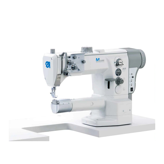
Spezialnähmaschine
•
Telefax +49 (0) 521 / 9 25 24 35 • www.duerkopp-adler.com
Printed in Federal Republic of Germany
869
Serviceanleitung
Service Instructions
Teile-Nr./Part.-No.:
0791 869641
D
GB
Advertisement
Table of Contents

Related Manuals for DURKOPP ADLER M-Type 869


Summary of Contents for DURKOPP ADLER M-Type 869
- Page 1 Spezialnähmaschine Serviceanleitung Service Instructions Postfach 17 03 51, D-33703 Bielefeld • Potsdamer Straße 190, D-33719 Bielefeld Telefon +49 (0) 521 / 9 25-00 • Telefax +49 (0) 521 / 9 25 24 35 • www.duerkopp-adler.com Ausgabe / Edition: Änderungsindex Teile-Nr./Part.-No.: 04/2010 Rev.
- Page 2 Alle Rechte vorbehalten. Eigentum der Dürkopp Adler AG und urheberrechtlich geschützt. Jede, auch auszugsweise Wiederverwendung dieser Inhalte ist ohne vorheriges schriftliches Einverständnis der Dürkopp Adler AG verboten. All rights reserved. Property of Dürkopp Adler AG and copyrighted. Reproduction or publication of the content in any manner, even in extracts, without prior written permission of Dürkopp Adler AG, is prohibited.
- Page 3 General safety instructions The non-observance of the following safety instructions can cause bodily injuries or damages to the machine. 1. The machine must only be commissioned in full knowledge of the instruction book and operated by persons with appropriate training. 2.
-
Page 5: Table Of Contents
Contents Page: Part 3: Service Instructions - Class 869 (Edition 04/2010) General information Gauges ........... . . Description of the locking positions . - Page 6 Contents Page: 2.12.1 Thread regulator ..........2.12.2 Thread take up spring .
-
Page 7: Gauges
General These service instructions describe how to set up the special 869 sewing machine. IMPORTANT! The tasks described in these service instructions must only be carried out by qualified or appropriately trained people. Caution: Danger of injury! Turn off the main switch for repair, conversion and maintenance work and disconnect the machine from the pneumatic supply system. -
Page 8: Description Of The Locking Positions
1.2 Description of the locking positions With the locking pin 1 and the marking grooves 2 and 3 in the needle bar crank 4 the sewing machine can be locked in two setting positions. Position I = Ø 5 mm locking pin for large groove = loop stroke, needle bar height Position II = Ø... -
Page 9: Graduated Scale On The Hand Wheel
1.3 Graduated scale on the hand wheel The hand wheel 2 is printed with graduated numbers. Specific settings are configured using these hand wheel settings. – Turn the hand wheel until it reaches the graduated figure specified in these instructions on the indicator 3. –... -
Page 10: Sewing Machine
Sewing machine 2.1 Position of the needle bar crank on the arm shaft Caution: Danger of injury! Turn off the main switch. Only check and adjust the position of the needle bar crank when the machine is switched off. Standard checking The needle bar crank 1 is fixed to the arm shaft with the two screws 2. -
Page 11: Top And Bottom Toothed Belt Wheel / Tooth Belt
2.2 Top and bottom sprocket belt wheel/ tooth belt 2.2.1 Position of the top sprocket belt wheel Caution: Danger of injury! Turn off the main switch. Only check and adjust the position of the top sprocket belt wheel when the machine is switched off. Standard checking The sprocket belt wheel 2 is fitted to the arm shaft 4 with two screws. -
Page 12: Bottom Feed And Stitch Regulator Gear
2.3 Bottom feed and stitch adjustment gear 2.3.1 Basic stitch adjustment setting Caution: Danger of injury! Turn off the main switch. Only set the basic stitch adjustment when the sewing machine is switched off. Standard checking When the adjustment wheel 5 is set to “0" the stitch adjuster drive 1 must have as little play as possible. - Page 13 Setting the eccentric The eccentric 2 must be set so that the marking 4 on eccentric 2 points away from the shaft 1. – Undo screw 3. – Turn eccentric 2 accordingly through hole 5. – Tighten screw 3.
-
Page 14: Setting The 2Nd Stitch Length
2.3.2 Adjust the 2 stitch length Caution: Danger of injury! Turn off the main switch. Only set the basic stitch adjustment when the sewing machine is switched off. – Turn the top adjustment wheel 1 to “4". – Remove screw 2 and remove the adjustment wheel 3. –... -
Page 15: Basic Feed Setting
2.3.3 Basic feed setting Caution: Danger of injury! Turn off the main switch. Only check and adjust the position of the feed dog and the stitch adjustment drive when the machine is switched off. Adjustment The basic setting is done when the stitch length is set to “0". Correction –... -
Page 16: Position Of The Feed Dog In The Throat Plate Cut Out
2.3.4 Position of the feed dog in the throat plate cut out Caution: Danger of injury! Turn off the main switch. Only check and adjust the position of the feed dog when the machine is switched off. Lateral alignment The feed dog should be at a uniform distance to the right and the left of the throat plate. -
Page 17: Feeding Motion Of The Feed Dog
2.3.5 Feeding motion of the feed dog 180° Caution: Danger of injury! Turn off the main switch. Only check and adjust the position of the feed dog when the machine is switched off. Standard checking When the machine is in position “5°” the feed dog must not move when the stitch adjuster lever is operated when the stitch is set to its maximum length. -
Page 18: Lifting Motion Of The Feed Dog
2.3.6 Lifting motion of the feed dog Caution: Danger of injury! Turn off the main switch. Only check and adjust the position of the feed dog stroke movement when the machine is switched off. Standard checking The feed dog should be the same distance from the throat plate at both the front and back dead centre: –... -
Page 19: Switching Off The Lifting Motion Of The Feed Dog For Edging Work
2.3.7 Switching off the lifting motion of the feed dog for edging work Caution: Danger of injury! Turn off the main switch. Only switch off the lifting motion of the feed dog when the sewing machine is switched off. – Remove screws 1 from the stroke eccentric. -
Page 20: Feed Dog Height
2.3.8 Feed dog height Caution: Danger of injury! Turn off the main switch. Only check and adjust the feed dog height when the machine is switched off. Standard checking Machines without feed dog stroke The feed dog should be the same height as the throat plate. Machines with feed dog stroke In order to ensure that the material being sewn feeds through properly the feed dog 2 must project 1.00 mm above the throat plate surface... -
Page 21: Transmission Lever
2.4 Transfer lever Caution: Danger of injury! Turn off the main switch. Only check and adjust the transfer lever when the machine is switched off. Standard checking Lever 3 transfers the movement of the feed shaft to the needle bar crank. -
Page 22: Needle Bar Linkage
2.5 Needle bar crank 2.5.1 Aligning needle bar crank to the side Caution: Danger of injury! Turn off the main switch. Only check and adjust the needle bar crank when the machine is switched off. Standard checking The needle must go through the middle of the feed dog needle hole. –... -
Page 23: Needle Hole In Feed Direction
2.5.2 Needle hole in feed direction Caution: Danger of injury! Turn off the main switch. Only check and adjust the needle hole when the machine is switched off. Standard checking The needle should go through the middle of the feed dog needle hole when a stitch length of “0”... -
Page 24: Hook, Looping Stroke And Needle Bar Height
2.6 Hook, loop stroke and needle bar height 2.6.1 Loop stroke Caution: Danger of injury! Turn off the main switch. Only check and adjust the loop stroke when the machine is switched off. Standard checking The loop stroke is the path of the needle bar from the top dead centre to the point at which the hook tip 2 is in the middle of needle 1. -
Page 25: Needle Bar Height
2.6.2 Needle bar height Caution: Danger of injury! Turn off the main switch. Only check and adjust the needle hole height when the machine is switched off. Standard checking The height of the needle bar should be set so that the hook tip is in the lower third of the channel when the stitch length is “0”... -
Page 26: Distance Between Hook And Needle
2.6.3 Distance between hook and needle Caution: Danger of injury! Turn off the main switch. Only check and adjust the hook distance when the machine is switched off. Standard checking In the loop stroke position the distance between the hook tip and the needle channel must be no more than 0.1mm. -
Page 27: Needle Guard
2.6.4 Needle guard Caution: Danger of injury! Turn off the main switch. Only check and adjust the needle guard when the machine is switched off. Standard checking The needle guard 2 should prevent the needle touching the hook tip. In the loop stroke position the needle should be pushed away slightly. –... -
Page 28: Bobbin Housing Elevator
2.7 Bobbin housing elevator 2.7.1 General The thread lever must draw the thread between the bobbin housing and its retainer. So that the thread can slip through unhindered, the bobbin housing must be raised at this time. As a result the required seam construction is achieved with the lowest possible thread tension. -
Page 29: Elevation Time
Correction – Turn eccentric bolt 2. The eccentric bolt 2 is held by the grub screw 1 and a plastic pressure piece. – The frictional force can be changed with grub screw 2 when the hook bearing is removed. 2.7.3 Elevation time The time of elevation is firmly preset by the eccentric on the hook and cannot be changed. -
Page 30: Feed Foot And Material Presser Foot
2.8 Feed foot and material presser foot 2.8.1 Feed foot and material presser foot stroke Caution: Danger of injury! Turn off the main switch. Only check and adjust the sewing feet stroke when the machine is switched off. Standard checking The strokes of the two sewing feet should be the same height when the adjustment wheel 5 for the sewing foot stroke setting is set to “3". -
Page 31: Feed Foot Stroke Movement
2.8.2 Feed foot stroke movement Caution: Danger of injury! Turn off the main switch. Only check and adjust the stroke movement when the machine is switched off. Condition · The same sewing foot and material presser foot stroke is set (see chapter 2.8.2) ·... -
Page 32: Sewing Foot Pressure
2.8.3 Sewing foot pressure Standard checking The material to be processed must not float. However, it should not be given any more pressure than necessary. Correction – Set the sewing foot pressure with screw 1. To increase sewing foot pressure = Turn screw 1 clockwise. -
Page 33: Stitch Length Limitation
2.9 Stitch length limitation Depending on the sewing equipment used the stitch length setting must be limited to 6 or 9 mm. – Remove screw 2 on the stitch length adjustment wheel. – Take out adjustment wheel 1. – Unscrew grub screw 4 and screw it into the corresponding hole. The holes have numbers. -
Page 34: Consistent Forward And Reverse Stitches
2.10 Consistent forward and reverse stitches Caution: Danger of injury! Turn off the main switch. Only set the stitch evenness when the sewing machine is switched off. Standard checking The stitch length for the forward and reverse stitch should be the same. -
Page 35: Sewing Foot Elevation
2.11 Sewing foot lifting 211.1 Sewing foot lifting (mechanical) Caution: Danger of injury! Turn off the main switch. Only check and adjust the play in the raising mechanism when the machine is switched off. Standard checking The elevating shaft 6 must be smooth running but must not have any axial play. -
Page 36: Height Of The Sewing Feet Locked With The Hand Lever
2.11.2 Height of the sewing feet locked with the hand lever Caution: Danger of injury! Turn off the main switch. Only check and adjust the sewing foot lifting when the machine is switched off. Standard checking The sewing feet 4 are locked into the raised position with hand lever 1 to change the sewing feet, for example, or to run the sewing machine without material or to wind the hook thread. -
Page 37: Height Of The Raised Sewing Feet
2.11.3 Height of the raised sewing feet Caution: Danger of injury! Turn off the main switch. Only check and adjust the height of the raised sewing feet when the machine is switched off. Standard checking The sewing feet 4 raised pneumatically or by using a knee lever should be 20 mm from the throat plate when the thread lever is at the top dead centre. -
Page 38: Thread Guiding Parts
2.12 Thread carrying parts 2.12.1 Thread regulator Caution: Danger of injury! Turn off the main switch. Only check and adjust the thread regulator when the machine is switched off. Standard checking The position of the thread regulator 1 depends on the thickness of the material, the thread thickness and the selected stitch length. -
Page 39: Thread Take Up Spring
2.12.2 Thread take up spring Caution: Danger of injury! Turn off the main switch. Only check and adjust the thread take up spring when the machine is switched off. Standard checking The adjustment rules for spring travel and spring tension apply to normal needle thread thicknesses. -
Page 40: Bobbin Winder
2.13 Bobbin winder Caution: Danger of injury! Turn off the main switch. Only check and adjust the bobbin winder when the machine is switched off. Standard checking The winding procedure must stop automatically when the bobbin is filled up to about 0.5 mm below the edge of the bobbin. The bobbin wheel should have no axial play but must also run smoothly. - Page 41 – Turn the bobbin winder spindle so that the cutting blade 12 points towards the right fixing screw 1. – Undo the screw on the engaging bracket 14. – Adjust the bobbin winder flap so that there is 2 - 3 mm of air between the thread on the bobbin and the bobbin winder flap (insert a spacer).
-
Page 42: Thread Cutter
2.14 Thread cutter 2.14.1 Thread pulling knife height Caution: Danger of injury! Turn off the main switch. Only check and adjust the thread pulling knife when the machine is switched off. Standard checking The thread pulling knife should go past the bobbin 3 at a distance of 0.3 mm. -
Page 43: Thread Pulling Knife
2.14.3 Thread pulling knife Caution: Danger of injury! Turn off the main switch. Only check and adjust the thread pulling knife when the machine is switched off. Standard checking When the thread pulling knife 1 is in its rest position the distance between the cam 4 (highest point) and the spool 5 should be 0.1 mm. -
Page 44: Cutter Pressure And Bobbin Thread Clamp
2.14.4 Cutter pressure and bobbin thread clamp Caution: Danger of injury! Turn off the main switch. Only check and adjust the counter blade and the bobbin thread clamp when the machine is switched off. Standard checking The thread should be cut reliably with the lowest possible pressure. Low cutting pressure keeps wear on the blades low. - Page 45 To adjust cutting pressure Adjustment For a flawless cutting operation it is important for screw 4 in the free arm to be up against the counter cutter support with a slight pressure and in this way it cannot be pressed down. Correction –...
- Page 46 To adjust the bobbin thread clamp – Unscrew bar 5. – Turn screw 6. Clockwise = clamping force higher Anti-clockwise = clamping force lower – Screw bar 5 on again.
-
Page 47: Cutting Position
2.14.5 Cutting position Caution: Danger of injury! Turn off the main switch. Only check and adjust the cutting position when the machine is switched off. Standard checking If the machine is at position 58° on the hand wheel the threads must be cut. -
Page 48: Potentiometer In The Arm
2.15 Potentiometer in the arm Sewing machines with thread cutters are fitted with a potentiometer to limit the speed with larger sewing foot strokes. The control unit detects this potentiometer in the sewing foot stroke and restricts the speed. 2.15.1 Basic setting without control panel Sewing machines without a control panel must be adjusted as described below. -
Page 49: Basic Setting With V810 Or V820 Control Panel
2.15.2 Basic setting with V810 or V820 control panel Caution: Danger of injury! The potentiometer is adjusted when the main switch is on. Work with appropriate precautions. – Undo the locking screw 1 for the potentiometer 2. – Press down and hold “P” and switch the main switch on. –... -
Page 50: Testing The Potentiometer Adjustment
2.15.3 Testing the potentiometer adjustment – Press down and hold “P” and switch the main switch on. – Access the technician level. – Select parameter “F-188”. – Press “E”. The current speedomat level and the relevant speed limit are displayed. –... -
Page 51: Oil Lubrication
2.16 Oil lubrication Caution: Danger of injury! Oil can cause skin rashes. Avoid excessive contact with the skin. Wash thoroughly after contact. IMPORTANT! The handling and disposal of mineral oils is subject to legal regulations. Deliver used oil to an authorized collecting station. Protect your environment. -
Page 52: Maintenance
2.17 Maintenance Caution: Danger of injury! Switch the main switch off. The sewing machine must only be maintained when it is switched off. The maintenance work to be carried out by the sewing machine operating personnel daily or weekly (cleaning and lubricating) are described in the operating instructions (Part 1).