Bose Lifestyle 18 Series II Installation Manual
Installation guide
Hide thumbs
Also See for Lifestyle 18 Series II:
- Quick setup manual (98 pages) ,
- Operating manual (44 pages) ,
- Installation manual (42 pages)
Table of Contents
Advertisement
Advertisement
Table of Contents

Related Manuals for Bose Lifestyle 18 Series II


Summary of Contents for Bose Lifestyle 18 Series II
- Page 1 LIFESTYLE ® DVD Home Entertainment Systems Installation Guide ®...
-
Page 2: Safety Information
Safety Information WARNING: To reduce the risk of fire or electric shock, do not expose the system to rain or moisture. WARNING: This apparatus shall not be exposed to dripping or splashing, and objects filled with liquids, such as vases, shall not be placed on the apparatus. As with any electronic prod- ucts, use care not to spill liquids in any part of the system. -
Page 3: System Information
Be sure to fill out your product registration card and mail it to Bose. Bose recommends that you keep your sales slip and a copy of your product registration card together with this guide. ©2004 Bose Corporation. No part of this work may be reproduced, modified, distributed or otherwise used without prior written permission. -
Page 4: Table Of Contents
Contents Where to find… Safety Information ..............Introduction . -
Page 5: Introduction
After unpacking your new system, save all packing materials; they may be useful as a safe way to transport your system. If any part of your system is missing or appears damaged, contact your authorized Bose dealer immediately, or contact Bose directly. Refer to the Bose address list included in the carton. -
Page 6: System Installation
System Installation Figure 1 Components of the ® LIFESTYLE DVD systems Media center power supply Media center Rubber foot for Jewel ® Cube ® speaker Your system will have five of one type of cube speaker: Single cube speaker ® (LIFESTYLE 18 Series II system) Jewel Cube... -
Page 7: Cables And Accessories
System Installation Cables and accessories Figure 2 Cables and accessories included with your system Audio input cable Front speaker cables Surround speaker cables Two component video adapters Stereo audio cable S-Video cable FM antenna Video cable (6 ft) AM loop antenna IR emitter cable Batteries Setup disc 1... -
Page 8: Placing Your Speakers
TV screen. Bose recommends a maximum distance of 3 feet (1 m) from the edge of the TV screen so that the sound does not become too separated from the picture. You may wish to vary this distance based on room conditions and personal preference. -
Page 9: Center Speaker Placement
System Installation Figure 4 ® Acoustimass Cube speaker array place- module Center ment and reflection rays Right Left front front Right surround Left surround Figure 5 Single cube speaker place- Acoustimass ment and reflection rays module Center Right Left front front Left surround Right surround... -
Page 10: Surround Speaker Placement
18 inches (45 cm) from the TV. Move it further if you still notice interference. • Place the Acoustimass module so that the grille with the Bose logo faces the room or is perpendicular to the wall. This prevents blocking the sound output or creating too much bass. -
Page 11: Placing Your Media Center
Note: Sending in the product registration card, included with your system, is very important if you want to receive software updates. Be sure to fill out the card and mail it to Bose. Select a location for the media center, keeping in mind the following guidelines: •... -
Page 12: Connecting The Speakers To The Acoustimass Module
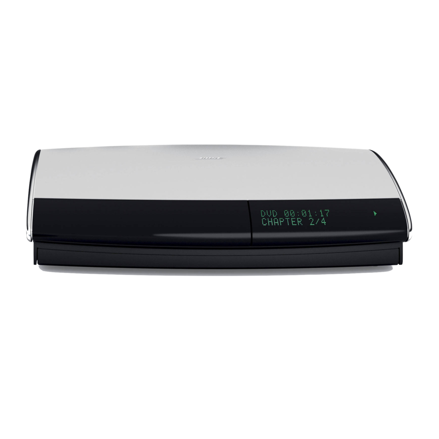
System Installation Figure 7 Front door – Make sure you have Display window – Make sure you can see enough room to lift this door. this information while using your system. Front features of the media center ® Disc tray – Make sure nothing blocks this The IR Emitter, which enables certain CD/DVD tray as it slides open. -
Page 13: Making The Two-Wire Connections For Cube Or Cube Array Speakers
® dealer or electronics store, or call Bose customer service. Refer to the Bose address list included with your system. In Figure 9, the wire marked with a red collar is positive (+) and the plain one is negative (–). - Page 14 System Installation 2. Connect the wire end of one speaker cable to the terminals on the rear of the matching speaker. • Press the terminal tab on the back of the speaker and insert the marked wire (+) into the red terminal and the plain wire (–) into the black terminal.
-
Page 15: Connecting The Acoustimass Module To The Media Center
System Installation Connecting the Acoustimass ® module to the media center Connect the Acoustimass module to the media center with the audio input cable (Figure 11). Note: Be sure that each connector is fully inserted into each jack. 1. You may find it easier to insert the power adapter cord into the media center first. Do not plug the other end into an AC (mains) power outlet until all connections are completed. -
Page 16: Connecting The Antennas
System Installation Connecting the antennas You should connect the additional AM and FM antennas, included with your system, to the rear panel of the media center (Figure 12). Figure 12 AM antenna lead FM dipole antenna lead Connections for the AM and FM antennas Media center rear panel Note: The FM jack (75 ohm) can be used with an outdoor antenna. -
Page 17: Connecting Your Tv To The System
System Installation Connecting your TV to the system The instructions below show basic connections to the media center and TV. This simple set of connections will allow you to use your system quickly. Later in this guide you will find other options for connecting additional components to your system. -
Page 18: Making A Video Connection
System Installation Making a video connection On your Media Center, connect the Composite Video Out to a Video In connection on your TV. See Figure 13. • Use a single cable with a yellow RCA connector on each end. • Remember the connection you used on your TV, such as VIDEO 1 or VIDEO 3, because that is the video input you must select, using your TV remote, to see a DVD picture or LIFE- ®... -
Page 19: Connecting The System To Power
System Installation Connecting the system to power Note: Bose recommends using a quality surge suppressor on all electronics equipment. Voltage variations and spikes can damage electronic components in any system. A quality suppressor can eliminate the vast majority of failures attributed to surges and may be pur- chased at electronics stores. -
Page 20: Installing The Remote Control Batteries
System Installation 4. If you have not plugged the small round connector of the media center power supply cable into the DC POWER jack on the media center connection panel, do so now (Figure 15). 5. Insert the power supply cord connector into the power supply and plug the cord into an AC (mains) outlet. -
Page 21: Finishing The Basic Installation
System Installation Finishing the basic installation Your system comes with two compact discs. Figure 17 ® ADAPTiQ audio calibration system Setup Disc 1 Setup discs and AdaptiQ audio calibration system Setup Disc 2 ADAPTiQ calibration headset • Setup Disc 1 provides information about your system and verifies that your speakers are connected correctly. - Page 22 System Installation Using the ADAPTiQ ® audio calibration system 1. Use the TV remote to turn on your television. 2. Select the video input connected to the LIFESTYLE ® system media center. 3. Lift up the media center front cover and press the Open/Close button. 4.
-
Page 23: Installing The Tv On/Off Sensor
System Installation Installing the TV on/off sensor The TV on/off sensor enables the system to automatically switch the TV on, as needed, when another video source (DVD, cable/satellite box, etc.) is selected. If you choose not to use the sensor, you need to turn on your TV separately. See Figure 19. Note: The TV on/off sensor is not included on LIFESTYLE ®... -
Page 24: Reference
TV. Video-grade cables from these jacks are not supplied and you will need to purchase them separately. Note: For more information, or to purchase the video cables, contact your local electronics store or authorized Bose ® dealer. Figure 20... -
Page 25: Connecting Your Vcr To The System
Note: If you have already used the video and audio cables supplied with your LIFESTYLE ® system, or your VCR does not provide any, you need to purchase additional cables. Contact your local electronics store or authorized Bose ® dealer. -
Page 26: Connecting Your Cable/Satellite Box To The System
This input will also provide better video quality when watching DVDs. To watch videotapes, select Input 1 on your TV (or the TV input to which you directly connected the VCR) and select the VCR sound source. Note: Additional cables may be purchased at an electronics store or authorized Bose ® dealer. -
Page 27: Using Component Video Connections
Reference Using Component video connections Follow the connection diagram in Figure 23 to achieve the best video quality for DVD and cable/satellite viewing, while adding a VCR to your home theater. Refer to “Component video” on page 24, if necessary. ®... -
Page 28: Connecting A Game Console
Reference Connecting a game console Connect a game console directly to an available TV input. To play, select that TV input and select TV audio on your LIFESTYLE ® system remote. See Figure 24. Figure 24 Connecting a game console... -
Page 29: Connecting Other Components
Reference Connecting other components Use standard RCA audio cables, matching the white (or black) connector to the L (left) channel and the red connector to the R (right) channel. See Figure 25. If the component is mono, use a Y adapter to connect it to the media center. Appropriate cables and adapters are available at most electronic stores. -
Page 30: Using Digital Audio Connections
Reference Figure 26 AUX input connections Media center connector panel CD changer or other playback equipment Using digital audio connections If your TV, VCR, tape deck, or AUX component has digital audio output jacks, you may con- nect them to the media center. In addition to the digital connection, be sure to connect L and R stereo outputs from the component to the media center. -
Page 31: Other Jacks On The Media Center Panel
4. Use the double-sided tape enclosed with the emitter to affix it in the proper position. Note: If you have questions, or need to obtain a replacement emitter, contact Bose customer service. Refer to the Bose address list included with your system. -
Page 32: Expanding Your System To Other Rooms
Operating Guide. How to decide what to add One option is using a Bose product you already own, if you want sound reproduced in just one additional room. To adapt legacy (pre-existing) Bose products for this purpose, you need to know: •... -
Page 33: How You Make It All Work Together
Bose SA-2 or SA-3 amplifier. This cable is included with the amplifier. A Bose ® link B cable is used to connect the LIFESTYLE ® system to a Bose 3•2•1 Series II or ® Bose Wave radio/CD II. -
Page 34: Accessories
See your Product Registration card for details. Please be sure to fill out the information sec- tion on the card and mail it to Bose. Failure to do so will not affect your limited warranty. Contacting customer service For additional help in solving problems, contact Bose customer service. - Page 35 Reference • D SPDIF Video OUT: • Composite: NTSC or PAL 1V with sync 75 • S-Video: Luminance 1V , Chrominance 0.3V • Component: (combination of Composite and S-Video) Remote control range 65 ft (20 m) Dimensions/Weights Media Center: 15.8"W x 11.0"D x 3.5"H 8.2 lb (3.7 kg) (40.1 cm x 27.9 cm x 8.9 cm) LIFESTYLE...
- Page 36 ©2004 Bose Corporation, The Mountain Framingham, MA 01701-9168 USA 274398 AM Rev.00 CCM-000363...