
Related Manuals for AMX AXP-PLV POSITRACK PILOT VIDEO TOUCH PANEL


Summary of Contents for AMX AXP-PLV POSITRACK PILOT VIDEO TOUCH PANEL
-
Page 1: Instruction Manual
instruction manual AXP-PLV PosiTrack Pilot Video Camera Controller (Firmware version G3) C a m e ra C o n t r o l S y s t e m s... - Page 2 This warranty extends only to products purchased directly from AMX Corporation or an Authorized AMX Dealer. AMX Corporation is not liable for any damages caused by its products or for the failure of its products to perform. This includes any lost profits, lost savings, incidental damages, or consequential damages. AMX Corporation is not liable for any claim made by a third party or by an AMX Dealer for a third party.
-
Page 3: Table Of Contents
Table of Contents Table of Contents Introduction .......................1 Specifications ........................1 Product Components......................2 Sample Product Application ....................3 Installation .........................5 Inside the AXP-PLV......................5 Setting the AXlink Device Numbers .................. 5 Wiring the AXP-PLV ......................6 Wiring guidelines........................6 Using the mini-XLR connector for AXlink data and power ............ - Page 4 Table of Contents Video Send_Commands ....................25 AXP-AI8 Send_Commands..................... 26 Programming Numbers ....................27 Shorthand Send_Commands..................28 Color Send_Commands....................32 Variable Text Send_Commands ..................34 Shorthand Variable Text Commands ................36 Button String Commands ....................39 Upgrading The Firmware ..................41 PosiTrack Pilot FG to TSK file relation...................
-
Page 5: Introduction
AXlink connection. This connection provides control of the pan/tilt, camera, and lens. The PosiPilot can be used in a stand-alone configuration with a Central Controller, compatible cameras, and positioning systems, or as part of a larger AMX control system. The PosiPilot combines traditional dual-axis proportional-speed joystick camera controls with an integrated Color Active Mini-Touch Panel to give you graphic touch control and on-screen video monitoring (with video input for NTSC/PAL). -
Page 6: Product Components
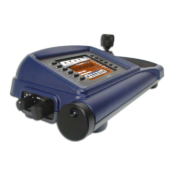
Introduction FIG. 2 AXP-PLV side panel dimensions Product Components The top of the PosiPilot is equipped with external pushbuttons, color video touch panel, and a 3-axis pan/tilt/zoom joystick. FIG. 3 gives a description of the AXP-PLV front panel components. Color video touch External panel for video preview External... -
Page 7: Sample Product Application
Introduction Sample Product Application FIG. 5 shows a camera control application using the AXP-PLV. AMX devices used for a single camera configuration are: Sample Devices Used NXC-ME260 NetLinx Master Controller AXB-PT15 Pan/Tilt Camera Head AXP-PLV PosiTrack Pilot Video Panel Camera Controller PS2.8... - Page 8 Introduction AXP-PLV PosiTrack Pilot Video Camera Controller...
-
Page 9: Installation
Installation Installation Inside the AXP-PLV The AXP-PLV unit contains two discrete AXlink devices: an AXP-AI8 (eight-channel analog input interface board) and a mini color video touch panel. The AXP-AI8 is connected to the joystick and knob functions of the AXP-PLV and is set to a factory default of 129. Level assignments for the AXP-AI8 inside the AXP-PLV are: AXP-AI8 Level Assignments Level 1... -
Page 10: Wiring The Axp-Plv
Installation 3. Set the AXlink device number by changing the AXlink device DIP switch positions 1 – 8 (FIG. 6). The total value of all ON (up) positions on the DIP switch sets the device number. The DIP switch value range is between 1 - 255, and is set according to the Device DIP switch positions and their corresponding values. -
Page 11: Using The Mini-Xlr Connector For Axlink Data And Power
Installation Using the mini-XLR connector for AXlink data and power Wire the Central Controller’s AXlink connector to the mini-XLR connector (male) on the rear panel of the AXP-PLV for data and 12 VDC power, as shown in FIG. 7. Four-pin mini-XLR connector (external view) 1 GND (-) - Black 2 AXM... - Page 12 Installation AXP-PLV PosiTrack Pilot Video Camera Controller...
-
Page 13: Designing Touch Panel Pages
Designing Touch Panel Pages Designing Touch Panel Pages There are two ways to approach creating touch panel pages: TPDesign3 - Refer to the TPDesign3 Touch Panel Program (Version 3. 16) instruction manual for more information. On-board editor This section describes the basics of using the on-board editor to create pages and buttons. For more information, refer to the G3 Firmware Design and Reference instruction manual. -
Page 14: Activating Edit Mode
Designing Touch Panel Pages General Button Categories (Cont.) Status buttons Status buttons always have a dark fill with light letters and have no functionality except to display information. Operation bars Operation bars appear in the place of the Editor bar, after selecting a button or page edit operation. - Page 15 Designing Touch Panel Pages To activate edit mode: 1. Press SETUP in the Main page to open the Setup page (FIG. 11). FIG. 11 Setup page 2. Press PROTECTED SETUP to open the keypad. 3. Enter 1988 (default password) in the keypad and press ENTER to open Protected Setup page. If you press ENTER after typing an incorrect password, you are immediately returned to the previous page.
-
Page 16: Setting The Device Base
Designing Touch Panel Pages Edit bar FIG. 13 Main page with Edit bar Setting the Device Base Press the DEVICE BASE option, in the Protected Setup page (FIG. 12), to assign a base (starting) device address to the touch panel. 1. -
Page 17: Setting The Page Color
Designing Touch Panel Pages Setting the page color 1. Press EDIT to open the Edit bar on the newly created page. 2. Press PAGE on the Edit bar to open the PAGE menu. 3. Press PAGE COLOR to open the color palette. 4. -
Page 18: Setting The Channel Code
Designing Touch Panel Pages Setting the channel code The channel button sets the device and button channel codes. Channel codes and variable text codes work the same for all button types, including joysticks, and bargraphs. 1. In the Button Properties page, press DEV to open the keypad and set the touch panel’s device number. -
Page 19: Setting The Button Colors For Channel-Off Conditions
Designing Touch Panel Pages Page FLIP type Flip to Page button button FIG. 14 Page FLIP Type button 4. Select the target page for the page flip. Setting the button colors for channel-off conditions 1. Press any button to open the Button Properties page. 2. -
Page 20: Creating A Bargraph And Joystick
Designing Touch Panel Pages 2. Select File from the menu bar to open the File menu. 3. In the File menu, click on Download to Panel; this opens the Download to Panel dialog box. 4. Click on the Comm Settings tab to set the communications port, baud rate, and other communication settings. -
Page 21: Setting The Level Code
Designing Touch Panel Pages Setting the level code Level buttons set the device and number codes for the touch panels. Joysticks actually use two level numbers. The first is for the X-axis and the second is for the Y-axis. You only need to specify the first level. 1. - Page 22 Designing Touch Panel Pages AXP-PLV PosiTrack Pilot Video Camera Controller...
-
Page 23: Programming
Programming Programming You can program the touch panel to perform a wide variety of operations using Axcess Send_Commands and variable text commands. Use the commands described in this section to program the touch panel. Refer to the Axcess Programming Language instruction manual for complete information. -
Page 24: System Send_Commands
Programming Serial Commands (Cont.) SETUP Syntax: Goes to Setup "SETUP" Page. Example: "SETUP" Flips the touch panel to the Setup page. Syntax: Restores the cur- "VER" rent vision. Example: "VER" This returns the current version of the main firmware. ZAP! Syntax: Clears all mem- "ZAP!"... - Page 25 Programming System Send_Commands (Cont.) AKEYP The keyboard string is set to null during power-up and is stored until power-down for. Opens the touch Syntax: panel keypad and "’AKEYP-<number string>’" initializes the Variables: number string entry. number string = 0 - 9999 Example: SEND_COMMAND TP,"’AKEYP-1988’"...
- Page 26 Programming System Send_Commands (Cont.) DBEEP This command only works if the Double Beep value in the Protected Setup page is set to Gives a double beep output. Syntax: "’DBEEP’" Example: SEND_COMMAND TP,"’DBEEP’" Double beeps the panel. ILEV Syntax: Inverts the joystick "’ILEV <joystick axis to invert>’"...
- Page 27 Programming System Send_Commands (Cont.) QBEEP Syntax: Stops all beeps. "’QBEEP’" Example: SEND_COMMAND TP,"’QBEEP’" Stops all beeps. RESET Syntax: Clears panel sta- "’RESET’" tus (same as Example: power up). Saved SEND_COMMAND TP,"’RESET’" data is not cleared. Resets the touch panel. SETUP Syntax: Goes to the Setup "’SETUP’"...
- Page 28 TPAGEON Syntax: Activates page "’TPAGEON’" tracking. Example: SEND_COMMAND TP,’TPAGEON’ DEFINE_DEVICE TP1 = 128 (*AMX Touch Panel*) TP2 = 129 (*AMX Touch Panel*) DEFINE_VARIABLE TP1_BUFFER[100] (*Buffer for TP1*) TP2_BUFFER[100] (*Buffer for TP2*) TRASH[50] (*For Parsing Above*) DEFINE_START CREATE_BUFFER TP1,TP1_BUFFER CREATE_BUFFER TP2,TP2_BUFFER SEND_COMMAND TP1,’TPAGEON’...
-
Page 29: Video Send_Commands
Programming System Send_Commands (Cont.) ZAP! Syntax: Clears all mem- "’ZAP!’" ory; erases but- Example: tons, pages, SEND_COMMAND TP, "’ZAP!’" drawings, and symbols. Clears all memory and erases all buttons, pages, drawings, and symbols. Only use the ZAP! command to erase all the saved data in the touch panel; data cannot be recovered after it is erased. -
Page 30: Axp-Ai8 Send_Commands
Programming Video Send_Commands (Cont.) @VSD Syntax: Sets the video "’@VSD’" default settings Variables: (brightness, con- data = 0 (min) - 255 (max) trast, saturation, hue). Example: SEND_COMMAND TP,"’@VSD’" Sets the incoming video values to their default settings. @VST Syntax: Sets the video sig- "’@VST<data>’"... -
Page 31: Programming Numbers
Programming Programming Numbers The following information provides the programming numbers for colors, fonts, and borders Colors can be used to set the colors on buttons, sliders, gauges, and pages. The lowest color number represents the lightest color-specific display; the highest number represents the darkest display. -
Page 32: Shorthand Send_Commands
Programming Border styles can be used to program borders on buttons, sliders, and gauges. Border Styles and Programming Numbers Border styles Border styles No border Double shadow No border special 3-dimensional rectangle 1 Single line 3-dimensional rectangle 2 Double line 3-dimensional round 1 Triple line 3-dimensional round 2... - Page 33 Programming Shorthand Send_Commands (Cont.) @CFF This only works if the specified background color is not the same as the current color. Sets the OFF Syntax: feedback fill color "’@CFF’,<variable text address>,<color_number>" to the specified Variables: color. variable text address = 1 - 255 color number = See the Colors and Programming Numbers table on page 27.
- Page 34 Programming Shorthand Send_Commands (Cont.) @CTN This only works if the specified background color is not the same as the current color. Sets the ON feed- Syntax: back text color to "’@CTN’,<variable text address>,<color_number>" the specified Variables: color. variable text address = 1 – 255 color number = See the Colors and Programming Numbers table on page 27.
- Page 35 Programming Shorthand Send_Commands (Cont.) @PPK If a pop-up page is part of a group, the whole group is deactivated. Deactivates a Syntax: popup page on all "’@PPK-<popup page name>’" touch panel Variables: pages. popup page name = target popup page name page name = target touch panel page name Example: SEND_COMMAND TP,"’@PPK-Laser Disc 2 Transport Control’"...
-
Page 36: Color Send_Commands
Programming Shorthand Send_Commands (Cont.) @SST Syntax: Changes the Star- "’@SST-<string>’" tup string sent to Variables: the Central Con- string = alphanumeric characters troller when the touch panel pow- Example: ers up. SEND_COMMAND TP,"’@SST-Touch Panel Power On’" Sends touch panel Power On to the Central Controller when the touch panel powers up. @SWK Syntax: Changes the... - Page 37 Programming Color Send_Commands (Cont.) CBOFF Syntax: Sets the OFF "’CBOFF<variable text address>-<color_number>’" feedback border Variables: color to the speci- variable text address = 1 - 255 fied color. color number = See the Colors and Programming Numbers table on page 27. Example: SEND_COMMAND TP,"’CBOFF1-72’"...
-
Page 38: Variable Text Send_Commands
Programming Color Send_Commands (Cont.) CTOFF Syntax: Sets the OFF "’CTOFF<variable text address>-<color _number>’" feedback text Variables: color to the speci- variable text address = 1 - 255 fied color. color number = See the Colors and Programming Numbers table on page 27. Example: SEND_COMMAND TP,"’CTOFF1-87’"... - Page 39 Programming Variable Text Send_Commands (Cont.) Syntax: Sets the border, "’!C’,<variable text address>,<border style>,<font font, and text in size>,’<new button text>’" one command. Variables: variable text address = 1 - 255 border style = See the Border Styles and Programming Numbers table on page 28. font size = See the Font Styles and Programming Numbers table on page 27.
-
Page 40: Shorthand Variable Text Commands
Programming Variable Text Send_Commands (Cont.) Syntax: Shorthand ver- "’!T’,<variable text address>,’<new button text>’" sion of 'TEXT' Variables: command. variable text address = 1 - 255 new button text = 1 - 60 characters Example: SEND_COMMAND TP,"’!T’,1,’VCR PLAY’" Changes the variable text button one title to VCR PLAY. TEXT Use the | character to display text on multiple lines. - Page 41 Programming Shorthand Variable Text Commands (Cont.) @BMF This command allows you to program up to 12 attributes on one command line. Sets multiple Syntax: attributes to a but- "’@BMF’,<variable text address>,’<attribute data>’" ton, slider, or Variables: gauge. variable text address = 1 - 255 attribute data: ’%R <left>, <top>, <right>, <bottom>’...
- Page 42 Programming Shorthand Variable Text Commands (Cont.) @FON Syntax: Sets the text font "’@FON’,<variable text address>,<font style>" on a button. Variables: variable text address = 1 - 255 font style = See the Font Styles and Programming Numbers table on page 27. Example: SEND_COMMAND TP, "'@FON',56,32"...
-
Page 43: Button String Commands
Programming Shorthand Variable Text Commands (Cont.) @TXT Use the | character to display text on multiple lines. Adds text to a but- Syntax: ton. "’@TXT’,<variable text address>,’<text>’" Variables: variable text address = 1 - 255 button text = Enter button text to appear on button. Example: SEND_COMMAND TP,"’@TXT’,2,’VCR|PLAY’"... - Page 44 Programming AXP-PLV PosiTrack Pilot Video Camera Controller...
-
Page 45: Upgrading The Firmware
4. Once the FG number has been identified; use one of the following associated TSK files to upgrade your units’ firmware. These TSK files can be found on the secure portion of the AMX.com website. Go to www.AMX.com > Tech Center > Downloadable Files > Firmware Files > PosiTrack section for the latest firmware files. -
Page 46: Upgrading The Firmware Using Netlinx Studio
The NetLinx Studio application can perform firmware upgrades for both Axcess and NetLinx devices using the options in the NetLinx Studio Firmware sub-menu. BEFORE beginning, download the correct TSK files from the AMX.com website. Refer to the NXC-ME260 Instruction manual for detailed setup information. - Page 47 FIG. 17 Sample NetLinx Project Navigator window 9. Right-click on a panel and select Properties to confirm the on-board firmware. Download the latest firmware file from AMX.COM > Tech Center > Downloadable FIles > Firmware Files > PosiTrack. Then Download the TSK file to your computer.
-
Page 48: Upgrading The Firmware Through An Ip Address
Upgrading The Firmware Selected Firmware file Device number listing of detected Axcess devices Device, Port, system, and version numbers of compatible firmware devices. Query Online Devices allows the user to refresh the list of detected Axcess devices FIG. 18 Select New PosiPilot Firmware File for download page -via COM Port 17. - Page 49 Upgrading The Firmware 1. Obtain the IP Address of the NetLinx Master from your System Administrator, if you do not have an IP Address for the Master: Follow steps outlined in the NetLinx Studio Instruction Manual for either Obtaining or Assigning and IP Address.
- Page 50 10. Right-click on a touch panel and select Properties to confirm the on-board firmware. Download the latest firmware file from AMX.COM > Tech Center > Downloadable FIles > Firmware Files > PosiTrack. Then Download the TSK file to your computer.
-
Page 51: Upgrading The Firmware Using Softrom
RAM to flash memory, the unit will not operate at all when power returns. If you have not already installed the SoftROM program, do so by logging into the AMX.com site and going to Dealers > Tech Center > Downloadable Files > Firmware Files. Scroll-down the list of products to find the PosiTrack Pilot firmware TSK files (see the PosiTrack Pilot FG to TSK file relation section on page 41 for information on which TSK to use). -
Page 52: Downloading The Firmware
Upgrading The Firmware 2. Using the up/down arrow keys, select the communications port you are using to interface with the controller and press ENTER. 3. Using the right arrow key, move to the BAUD RATE column. Then, use the up/down arrow keys to select the interface communications speed and press ENTER. - Page 53 Upgrading The Firmware AXP-PLV PosiTrack Pilot Video Camera Controller...
- Page 54 ATLANTA • BOSTON • CHICAGO • CLEVELAND • DALLAS • DENVER • INDIANAPOLIS • LOS ANGELES • MINNEAPOLIS • PHILADELPHIA • PHOENIX • PORTLAND • SPOKANE • TAMPA 3000 RESEARCH DRIVE, RICHARDSON, TX 75082 USA • 800.222.0193 • 469.624.8000 • 469-624-7153 fax • 800.932.6993 technical support • www.amx.com...