
Related Manuals for AMX AXB-REL8


Summary of Contents for AMX AXB-REL8
- Page 1 AXB-REL8 Axcess Relay Controller A X l i n k B u s C o n t r o l l e r s...
- Page 2 This warranty extends only to products purchased directly from AMX Corporation or an Authorized AMX Dealer. AMX Corporation is not liable for any damages caused by its products or for the failure of its products to perform. This includes any lost profits, lost savings, incidental damages, or consequential damages. AMX Corporation is not liable for any claim made by a third party or by an AMX Dealer for a third party.
-
Page 3: Table Of Contents
Wiring AXlink with optional 12 VDC power supply ... 5 Checking the installation ... 5 Relay connections... 5 Testing the installation ... 6 Rack-Mounting the AXB-REL8 (optional)... 6 System Worksheet and Installation Guide ... 7 AXB-REL8 Axcess Relay Controller Table of Contents... - Page 4 Table of Contents AXB-REL8 Axcess Relay Controller...
-
Page 5: Product Information
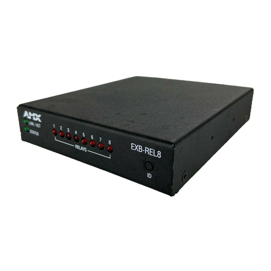
Product Information The AXB-REL8 Relay Controller provides remote control for up to eight relay functions. Suitable for stand-alone or rack mount applications, the AXB-REL8 may be used with AXCESS or AXCENT systems via the four-wire AXlink data bus. Front and Rear Panels The front and rear panels of the AXB-REL8 are shown in FIG. - Page 6 Eight (normally -open) isolated two-pin relay contacts 1 A @ 28 VAC or VDC: • Relays 1-4 can share a common if use jumper"A" pins with a tab strip • Relays 5-8 use discrete commons (wire commons individually) AXB-REL8 Axcess Relay Controller...
-
Page 7: Connection And Wiring
Setting the DEVICE Dip Switch The eight-position Device DIP switch is located on the front panel of the AXB-REL8 as shown in FIG. 1 on page 1. Each device in the AXlink bus must have a unique AXlink device number. -
Page 8: Preparing Captive Wires
Connection and Wiring Do not connect power to the AXB-REL8 until the wiring is complete. If you are using a 12 VDC power supply, apply power to the AXB-REL8 only after installation is complete. Preparing captive wires To connect the wiring into a captive-wire connector: 1. -
Page 9: Axlink Data And Power Connections
170 ma (max) draw of the AXB-REL8. Make sure to connect the GND and +12 VDC wire on the AXB-REL8 AXlink connector end. Do not connect the optional +12 VDC power supply wire to the control system's power supply side of the AXlink connector (FIG. -
Page 10: Testing The Installation
4. Place the unit in the appropriate opening in the AC-RK. 5. Place the front panel of the AXB-REL8 on the front of the rack, over the unit. 6. Fasten the front panel to the rack and to the unit with the two screws you removed. -
Page 11: System Worksheet And Installation Guide
System Worksheet and Installation Guide AXB-REL8 Dealer ID# Dealer Description Device # AXB-REL8 Axcess Relay Controller Serial# AXlink Function Color/Pin Wiring Connection and Wiring AMX Cable/Infc # Source... - Page 12 AMX reserves the right to alter specifications without notice at any time. brussels • dallas • los angeles • mexico city • philadelphia • shanghai • singapore • tampa • toronto* • york 3000 research drive, richardson, TX 75082 USA • 469.624.8000 • 800.222.0193 • fax 469.624.7153 • technical support 800.932.6993...