Table of Contents
Advertisement
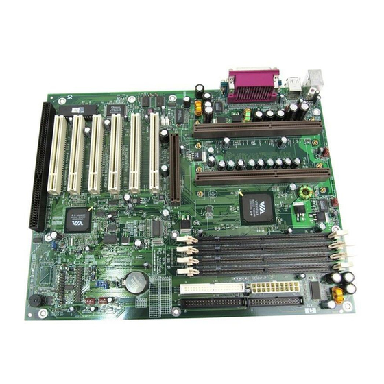
Tyan S1834
Tiger 133
Motherboard User's Manual
Revision 1.20
Copyright © Tyan Computer Corporation, 2000. All rights reserved. No part of this
manual may be reproduced or translated without prior written consent from Tyan
Computer Corp.
All registered and unregistered trademarks and company names contained in this
manual are property of their respective companies including, but not limited to the
following.
Award is a trademark of Phoenix Technologies Ltd.
Windows is a trademark of Microsoft Corporation.
IBM, PC, AT, PS/2 are trademarks of IBM Corporation.
INTEL, Pentium II/ III, Celeron are trademarks of Intel Corporation.
S1834 Tiger 133 are trademarks of TYAN Computer Corporation.
Information contained in this publication has been carefully checked for accuracy and
reliability. In no event will Tyan Computer be held liable for any direct or indirect,
incidental or consequential damage, loss of use, loss of data, or other malady resulting
from errors or inaccuracies of information contained in this manual. The information
contained in this document is subject to change without notice.
PRINTED IN TAIWAN
Advertisement
Table of Contents

Related Manuals for TYAN TIGER 133


Summary of Contents for TYAN TIGER 133
- Page 1 Information contained in this publication has been carefully checked for accuracy and reliability. In no event will Tyan Computer be held liable for any direct or indirect, incidental or consequential damage, loss of use, loss of data, or other malady resulting from errors or inaccuracies of information contained in this manual.
-
Page 2: Table Of Contents
Table of Contents 1. Introduction....................4 Overview.....................4 Icons....................5 Hardware Specifications/Feaures..........6 Technical Support................8 Returning Merchandise for Service..........8 2. Board Installation..................9 Unpacking..................9 Installation..................9 Quick Reference for Jumpers............11 Map of Motherboard Jumpers............. 12 Setting Jumpers................14 Clear CMOS & Reset Password ..........15 Soft Power Connector.............. - Page 3 4. System Resources..................62 Beep Codes..................62 Appendix Glossary..................63 Compliance Information................70...
-
Page 4: Introduction
Overview The S1834 Tiger 133 is a quality, high performance motherboard designed for dual Intel PII / PIII microprocessors. The Tiger 133 utilizes the VIA Apollo Pro 133A chipset (VT82C694X) with Award BIOS. The S1834 can support CPU speeds of 450MHz through 800+MHz, and host bus speeds of 100 MHz to 133 MHz (the VIA chipset’s bus speed is Auto-Determined by the CPU). -
Page 5: Icons
Prevent damage to yourself and to your board: always ensure that your system is turned off and unplugged whenever you are working with it, and that you are equipped with a static safety device. S1834 Tiger 133... -
Page 6: Hardware Specifications/Feaures
One ISA slot (shared w/ a PCI slot) Seven total usable slots Integrated PCI IDE Two 40-pin IDE connectors for up to 4 drives UltraDMA33/66 supported ATAPI IDE CD-ROM and LS-120 supported * See TYAN website for CPU Compatibility List: www.tyan.com http://www.tyan.com... -
Page 7: Software Specifications
European Community CE (Declaration of Conformity) Software Specifications •Operates with MS-DOS ver 6.22, Windows 98 & Win98 SE, Windows NT 4.0, Novell 5.0 Windows 2000(RC3) pending, SCO Unix 5.01 Linux 6.0 Please refer to http://www.tyan.com for OS updates S1834 Tiger 133... -
Page 8: Technical Support
Return Merchandise Authorization (RMA) number. The RMA number should be prominently displayed on the outside of the shipping carton and the package should be mailed prepaid, or hand-carried to the manufacturer. TYAN will pay to have the board shipped back to you. http://www.tyan.com... -
Page 9: Board Installation
(1) Driver CD (2) URM Retention Modules (Terminator card is currently not needed on this board when using only a single processor. Check http://www.tyan.com for information and updates concerning CPUs.) Installation You are now ready to install your motherboard. The mounting hole pattern of the S1834 matches the ATX system board specifications. -
Page 10: Installation Steps
1. Set Jumpers procedure 2. Mount Motherboard in Chassis 3. Install Memory 4. Install CPU & Cooling Fan 5. Connect IDE and Floppy Drives 6. Connect Power Supply 7. Install Add-on Cards 8. Connect PS/2, USB, Serial and Parallel Devices http://www.tyan.com... -
Page 11: Quick Reference For Jumpers
CPU speed, Infrared, and external connector pin assignments, among others. The miniature motherboard maps will help you locate the jumpers on your board. A full-page map of the motherboard can be found on the next two pages. S1834 Tiger 133... -
Page 12: Map Of Motherboard Jumpers
PCI slot 3 PCI slot 4 FAN4 VT82C596B PCI slot 5 JP14 JP10 PCI slot 6 Clear CMOS ISA slot The tiny “1”s next to jumpers of 3 pins or more indicate the position of pin 1 for that jumper. http://www.tyan.com... - Page 13 Figure 2-4 : Map of S1834 Features VIA Apollo Pro 133A Chipset 4 DIMM slots 2 SECC slots 1 ISA slot Award BIOS S1834 Tiger 133...
-
Page 14: Setting Jumpers
JP4 -7 according to the specification of your CPU using the chart below. After the system is ready to boot the BUS Speed is auto-detected. Presently all Celeron CPUs use a 66MHz bus speed. (Tyan does not recom- mend operating CPUs, memory, or PCI Bus at higher than rated speed. Tyan... -
Page 15: Clear Cmos & Reset Password
3. Wait for 2 seconds, then return jumper JP10 to pins 1 and 2. 4. Power on the system again. By following this procedure, you will erase your password and reset the CMOS to the BIOS defaults. S1834 Tiger 133... -
Page 16: Soft Power Connector
Board Installation 1-F. Soft Power Connector The Soft Power Connector is part of jumper block J10. The Tiger 133 uses the chipset for power management, including turning on and off the system. If the Power Button Function option in the BIOS Power Management Menu is set to On/Off (which is the default), pressing the power button once after the BIOS has booted up will turn the system on and off. -
Page 17: Flash Eeprom
Flash EEPROM The Tiger 133 uses flash memory to store BIOS firmware. It can be updated as new versions of the BIOS become available. You can upgrade your BIOS easily using the flash utility (see page 59). 2. Mounting the Motherboard in the Chassis Follow the instructions provided by the case manufacturer for proper installa- tion guidelines. - Page 18 DIMM (see Figure 2-6 on the next page). To remove your DIMM, simply pull the clips back, and pull up on the module. Place the DIMMs in an anti-static bag as soon as you remove them to avoid static damage. http://www.tyan.com...
- Page 19 *Note: The image above is used to illustrate a concept and may not represent the actual image of your motherboard. The Tiger 133 uses a 64-bit data path from memory to CPU and can accommo- date up to 2 GB of PC100 SDRAM and up to 1.5GB of PC133 SDRAM. The 168-pin DIMMs (Dual In-line Memory Modules) must be of the 3.3V,...
- Page 20 Chapter 2 Board Installation The table below shows some of the possible memory configurations. Not all possible configurations are listed. l a t *1.5GB memory capacity applies only to PC133 SDRAM. http://www.tyan.com...
-
Page 21: Installing The Cpu And Cooling Fan
4. Installing the CPU and Cooling Fan Slot 1 type Pentium II/III can be used on the Tiger 133. Please refer to page 15 for the correct CPU jumper settings for your CPU. Remember: • The CPU is a sensitive electronic component and it can easily be damaged by static electricity. - Page 22 “snap” into the sides of the CPU. The installed CPU should look like Figure 2-12 on the following page. Figure 2-11* *Note: The images on these two pages are used to illustrate a concept and may not represent the actual image of your motherboard. http://www.tyan.com...
- Page 23 To remove the CPU, gently bend the sides of the retention brace away from the CPU and slowly pull the CPU upwards. This may require careful firm tugs to pull the CPU out of its slot. Figure 2-13* S1834 Tiger 133...
-
Page 24: Connecting Ide And Floppy Drives
• Hard drive lights are constantly on: bad IDE cable or defective drives/ motherboard. Try another HDD. • Hard drives do not power up: check power cables and cabling. May also be a bad power supply or IDE drive. http://www.tyan.com... -
Page 25: Connecting Floppy Drives
Try another cable or floppy drive to verify. • Light on the floppy is on constantly: a dead giveaway that the cable is on backwards. Reverse the cable at the motherboard end and try again. S1834 Tiger 133... -
Page 26: Installing Add On Cards
It is fast enough to support video transfer, and is capable of supporting up to 127 daisy-chained peripheral devices. Figures 2-16 and 2-17 on the following page shows the USB ports on the left and PS/2 ports on the right (respectively). http://www.tyan.com... -
Page 27: Connecting Com And Printer Ports
“hot plugging,” and may damage your system.Figure 2-18 above shows the ATX double row connectors on this board. The Com and Printer ports, as well as the other ports, are labeled. S1834 Tiger 133... -
Page 28: Connecting The Power Supply
8. Connecting the Power Supply Tyan recommends using an ATX power supply that conforms to industry standard revision 2.01. The Tiger 133 motherboard comes equipped with one onboard power connector. Figure 2-16 below shows an ATX power connector. When plugging in the power connector, make sure that the plastic clip on the power connector is aligned with the plastic tab on the onboard connector (see Figure 2-17 below). -
Page 29: Bios Configuration
The rest of this manual is intended to guide you through the process of configuring your system using Setup. S1834 Tiger 133... -
Page 30: Starting Setup
Getting Help Press F1 to pop up a small help window that describes the appropriate keys to use and the possible selections for the highlighted item. To exit the Help Window press <Esc> or the F1 key again. http://www.tyan.com... -
Page 31: In Case Of Problems
The Chipset defaults have been carefully chosen by Award Software or your system manufacturer for the best performance and reliability. Even a seemingly small change to the Chipset setup may causing the system to become un- stable. S1834 Tiger 133... -
Page 32: Main Setup Menu
Power Management Setup Save & Exit Setup w w w w w PnP/PCI Configurations Exit Without Saving w w w w w PC Health Status Esc : Quit : Select Item F10 : Save & Exit Setup (Shift)F2 : Change Color http://www.tyan.com... - Page 33 Set User Password Change, set, or disable a password. The user password generally allows only power-on access. Save & Exit Setup Save settings in nonvolatile CMOS RAM and exit Setup. Exit Without Saving Abandon all changes and exit Setup. S1834 Tiger 133...
-
Page 34: Standard Cmos Setup
The time format is based on the 24-hour military-time clock. For example, 1 p.m. is 13:00:00. Press the arrow keys to move to the desired field. Press the PgUp or PgDn key to increment the setting, or type the desired value into the field. http://www.tyan.com... - Page 35 1. Match the specifications of your installed IDE hard drive(s) with the preprogrammed values for drive types 1 through 45. 2. Select User and enter values into each drive parameter field. 3. Use the IDE HDD Auto Dectection function in Setup. S1834 Tiger 133...
- Page 36 LBA (Logical Block Addressing): During drive accesses, the IDE controller transforms the data address described by sector, head, and cylinder number into a physical block address, significantly improving data transfer rates. For drives with greater than 1024 cylinders. http://www.tyan.com...
- Page 37 , l l . s r e t t e v i , l l e t t . s r k s i , l l k s i . s r S1834 Tiger 133...
- Page 38 Other Memory: Between 640 KB and 1 MB; often called high memory. DOS may load terminate-and-stay-resident (TSR) programs, such as device drivers, in this area, to free as much conventional memory as possible for applications. Lines in your config.sys file that start with loadhigh load programs into high memory. http://www.tyan.com...
-
Page 39: Advanced Bios Features Setup
OS Select For DRAM > 64MB Non-OS2 Video BIOS Shadow Enabled C8000-CBFFF Shadow Disabled CC000-CFFFF Shadow Disabled D0000-D3FFF Shadow Disabled D4000-D7FFF Shadow Disabled D8000-DBFFF Shadow Disabled DC000-CFFFF Shadow Disabled :Move Enter:Select +/-/PU/PD:Value F10:Save ESC:Exit F1:General Help F5:Previous Values F6:Fail-Safe Defaults F7:Optimized Defaults S1834 Tiger 133... -
Page 40: Virus Warning
If you plan to run such a program, we recommend that you first disable the virus warning. CPU Internal Cache/External Cache Cache memory is additional memory that is much faster than conventional DRAM (system memory). CPUs from 486-type on up contain internal cache http://www.tyan.com... - Page 41 Disabled to save time. Boot Up NumLock Status Toggle between On or Off to control the state of the NumLock key when the system boots. When toggled On, the numeric keypad generates numbers instead of controlling cursor operations. S1834 Tiger 133...
- Page 42 16-bit or 32-bit DRAM bus. Firmware not shadowed must be read by the system through the 8-bit X-bus. Shadowing improves the performance of the system BIOS and similar ROM firmware for expansion peripherals, but it also reduces the amount of high memory (640 KB to 1 MB) http://www.tyan.com...
- Page 43 BIOS Features Setup screen may be occupied by other expan- sion card firmware. If an expansion peripheral in your system contains ROM- based firmware, you need to know the address range the ROM occupies to shadow it into the correct area of RAM. S1834 Tiger 133...
-
Page 44: Advanced Chipset Features Setup
Enabled PCI Delay Transaction Disabled PCI#2 Access #1 Retry Disabled AGP Master 1 WS Write Disabled AGP Master 1 WS Read Disabled Memory Parity/ECC Check Disabled :Move Enter:Select +/-/PU/PD:Value F10:Save ESC:Exit F1:General Help F5:Previous Values F6:Fail-Safe Defaults F7:Optimized Defaults http://www.tyan.com... -
Page 45: Sdram Cycle Length
CAS access time by 1 clock tick. SDRAM Cycle Length This field sets the CAS latency timing. DRAM Clock Allows you to set the memory clock speed to either 66MHz or equal to the CPU clock speed, depending on your memory speed. S1834 Tiger 133... - Page 46 Enables the 4X AGP mode for higher AGP throughput. A 4X AGP graphics card is required to enable this function. Due to Tyan’s commitment to advanced technologies and first to market, not all high performance 4X AGP graphics cards are compatible w/ our S1834 at the time of print, please go to our web site for the latest update.
- Page 47 Memory Parity / ECC Check Select Enabled, Disabled, or Auto. In Auto mode, the BIOS enables memory checking automatically when it detects the presence of ECC or parity DRAM. NOTE: ECC memory functions are not supported on the Tiger 133 S1834. S1834 Tiger 133...
-
Page 48: Intergrated Peripherals
Hi,Lo IR Transmission delay Enabled Onboard Parallel Port 378/IRQ7 Onboard Parallel Mode Normal X ECP Mode Use DMA Parallel Port EPP Type EPP1.9 PWRON After PWR-Fail :Move Enter:Select +/-/PU/PD:Value F10:Save ESC:Exit F1:General Help F5:Previous Values F6:Fail-Safe Defaults F7:Optimized Defaults http://www.tyan.com... - Page 49 This chipset contains a PCI IDE interface with support for two IDE channels. Select Enabled to activate the primary and/or secondary onboard IDE inter- face. Select Disabled to deactivate this interface, if you install a primary and/or secondary add-in IDE interface. S1834 Tiger 133...
- Page 50 Disabled in this field. Onboard Serial Port 1/ 2 Select a logical COM port address and corresponding interrupt for the first and second serial ports. The second serial port offers infrared options in the next field. http://www.tyan.com...
- Page 51 If it is set to On, the computer will power on when power is restored. If the setting is set to Former-Sts, the computer will return to the previous state before the power was interrupted. S1834 Tiger 133...
-
Page 52: Power Management Setup
This table describes each power management mode: l i a v i t y t i . y l l i f e o i t o l l v i t y t i v i r . ) e http://www.tyan.com... - Page 53 After the selected period of system inactivity (1 minute to 1 hour), all devices except the CPU shut off. ACPI Suspend Type This setting controls the type of suspend function that is enabled once the computer has gone into suspend mode. S1834 Tiger 133...
-
Page 54: Video Off Option
4 seconds, with only enough circuitry receiving power to detect wake-up event activity. Wake Up Events A power management (PM) event awakens the system from, or resets activity timers for, Suspend mode. http://www.tyan.com... - Page 55 When On, any DMA or bus master activity is a PM event. Wake Up on LAN This feature allows remote power up through a LAN connection when used in conjunction with a Wake on LAN compliant network adapter and appropriate software. S1834 Tiger 133...
-
Page 56: Primary Intr
IRQ0 (System Timer) IRQ7 (LPT1) IRQ1 (Keyboard) IRQ8 (RTC Alarm) IRQ2 (Cascade- Reserved) IRQ9 (FREE) IRQ3 (COM2) IRQ10 (FREE) IRQ4 (COM1) IRQ11 (FREE) IRQ5 (FREE) IRQ12 (PS/2 Mouse) IRQ6 (Floppy Disk) IRQ13 (Coprocessor) IRQ14 (Primary IDE) IRQ15 (Seconday IDE) http://www.tyan.com... -
Page 57: Pnp/Pci Configuration
Normally, you leave this field Disabled. Select Enabled to reset Extended System Configuration Data (ESCD) when you exit Setup if you have installed a new add-on and the system reconfiguration has caused such a serious conflict that the operating system cannot boot. S1834 Tiger 133... - Page 58 PCI or ISA bus architecture. PCI / VGA Palette Snoop Please leave this field at Disabled. Assign IRQ for VGA Assign an IRQ number to your VGA adapter. Assign IRQ For USB Assign an IRQ number to your USB device / controller. http://www.tyan.com...
-
Page 59: Flash Writer Utility
You can upgrade the BIOS on your motherboard by using the Flash Memory Writer (FMW) utility. This utility can be downloaded from TYAN’s BBS and from the TYAN website. The system BIOS is stored on a flash EEPROM chip on the mainboard, which can be erased and reprogrammed by the FMW. The following three files make up the FMW: AWDFLASH.EXE... - Page 60 BIOS file is in the same directory as the FMW utility. To start FMW, change to the “Flash” directory if you are not already in it. Type “awdflash” at the DOS command line and press the <Enter> key. The FMW utility screen will appear: http://www.tyan.com...
- Page 61 Warning: If you do not successfully install a complete BIOS file in the flash memory on the mainboard, your system may not be able to boot. If this hap- pens, it will require service by your system vendor. Follow the instructions in this section precisely to avoid such an inconvenience. S1834 Tiger 133...
-
Page 62: System Resources
Currently the only beep code indicated that a video error has occured and the BIOS cannot initialize the video screen to display any additional information. This beep code consists of a single long beep followed by two short beeps. Any other beeps are probably a RAM problem http://www.tyan.com... - Page 63 CPU is closer to the power supply and cooling fan. The keyboard, mouse, serial, USB, and parallel ports are built Bandwidth refers to carrying capacity. The greater the bandwidth, the more S1834 Tiger 133...
-
Page 64: Appendix Glossary
Closed and open jumpers Jumpers and jumper pins are active when they are On or Closed, and inactive when they are Off or Open. CMOS Complementary Metal-Oxide Semiconductors are chips that hold the basic start-up information for the BIOS. http://www.tyan.com... - Page 65 ROM chip which can, unlike normal ROM, be updated. This allows you to keep up with changes in the BIOS programs without having to buy a new chip. TYAN’s BIOS updates can be found on the website. ESCD (Extended System Configuration Data) is a format for storing informa- tion about Plug and Play devices in the system BIOS.
- Page 66 Form factor is an industry term for the size, shape, power supply type, and external connector type of the PCB (personal computer board) or motherboard. The standard form factors are the AT and ATX, although TYAN also makes some Baby-AT boards.
- Page 67 Plug and Play-aware operating system (such as Windows 95), and go to work. Devices and operating systems that are not Plug and Play require you to reconfigure your system each time you add or change any part of your hardware. S1834 Tiger 133...
- Page 68 Universal Serial Bus or USB, is a versatile port. This one port type can function as a serial, parallel, mouse, keyboard, or joystick port. It is fast enough to support video transfer, and is capable of supporting up to 127 http://www.tyan.com...
- Page 69 ZIF socket Zero Insertion Force sockets make it possible to insert CPUs without damaging the sensitive pins. The CPU is lightly placed in an open ZIF socket, and the metal lever pulled down. This shifts the processor over and down, guiding it into place on the board. S1834 Tiger 133...
-
Page 70: Compliance Information
Dispose of used batteries according to manufacturer instructions.F1 (Fuse 1), F2 (Fuse 2): Rated 30V DC, hold current at 1.6 A. Note: The joystick port maximum output rating is 9 amperes at 5 volts. Document # D1396-120 http://www.tyan.com...