Konica Minolta MS7000 MK II User Manual
Microfilm scanner
Hide thumbs
Also See for MS7000 MK II:
- Installation and user manual (59 pages) ,
- User manual (28 pages) ,
- User manual (154 pages)
Table of Contents
Advertisement
Quick Links
Advertisement
Table of Contents

Related Manuals for Konica Minolta MS7000 MK II


Summary of Contents for Konica Minolta MS7000 MK II
- Page 1 MS7000 MKII User's Guide...
-
Page 2: Energy Star
® Energy Star ® As an ENERGY STAR Partner, we have determined that this machine meets the ENERGY ® STAR Guidelines for energy efficiency. ® What is an ENERGY STAR Product? ® An ENERGY STAR product has a special feature that allows it to automatically switch to a ®... -
Page 3: Safety Information
SAFETY INFORMATION This section contains detailed instructions on the operation and maintenance of this machine. To achieve optimum utility of this device, all operators should carefully read and follow the instructions in this manual. Please keep this manual in a handy place near the machine. - Page 4 SAFETY INFORMATION • Do not modify this product, as a fire, electrical shock, or break- down could result. If the product employs a laser, the laser beam source could cause blindness. • Do not attempt to remove the covers and panels which have been fixed to the product.
- Page 5 SAFETY INFORMATION Do not place a flower vase or other container that contains water, or metal clips or other small metallic objects on this product. Spilled water or metallic objects dropped inside the product could result in a fire, electrical shock, or breakdown. Should a piece of metal, water, or any other similar foreign matter get inside the product, immediately turn OFF the power switch, unplug the power cord from the power outlet, and then call your...
- Page 6 SAFETY INFORMATION • Do not use flammable sprays, liquids, or gases near this product, as a fire could result. • Do not leave a toner unit or drum unit in a place within easy reach of children. Licking or ingesting any of these things could injure your health.
- Page 7 SAFETY INFORMATION • Always use this product in a well ventilated location. Operating the product in a poorly ventilated room for an extended period of time could injure your health. Ventilate the room at regular intervals. • Whenever moving this product, be sure to disconnect the power cord and other cables.
- Page 8 SAFETY INFORMATION Do not touch or scratch the surface of the toner unit developing roller and the PC drum, as poor image quality could result. Use the supplies and consumables recommended by the dealer. Use of any supply or consumable not recommended could result in poor image quality and breakdown.
- Page 9 Welcome Welcome This User’s Guide explains how to operate the unit and replenish its supplies. It also gives some troubleshooting tips as well as general precautions to be observed when operating the unit. To ensure the best performance and effective use of your unit, read this User’s Guide carefully until you familiarize yourself thoroughly with the unit's operation and features.
-
Page 11: Table Of Contents
Contents Contents Notes to Operators and Key Operators The following safety rules should be observed ......1-1 FCC Part 15 - Radio Frequency Devices (For U.S.A. Users)..1-1 WARNING ..................1-1 Interference-Causing Equipment Standard (ICES-003 ISSUE 3) (For Canada Users) ................. 1-2 CE Marking (Declaration of Conformity) (For European Users) .. - Page 12 Contents Parts of the Scanner................3-3 Control Panel Keys and Indicators ...........3-5 Control Panel 1 (Basic) ..............3-5 Control Panel 1 (Shift Function) ............3-9 Control Panel 2 ................3-10 When Misfeed/Call-Tech.-Rep. Indicator Lights up......3-12 Image Processing Functions............3-14 Turning the Power On and Off............3-16 Turning ON..................3-16 Turning OFF...................3-17 Auto Power Save Mode ..............3-18...
- Page 13 Contents Selecting Auto Masking ..............3-33 Operating Conditions for Auto Masking ......... 3-33 3.19 Manual Masking Panels (Option) ............ 3-34 3.20 Using Manual Masking ..............3-35 Selecting Trimming ................ 3-35 Defining an Area ................3-36 Defining Two Separate Areas............3-36 Defining Page-by-Page Print Area..........
- Page 14 Contents Clearing a Misfeed from the Paper Feeding Tray ......4-10 Clearing a Misfeed from the Paper Cassette .........4-12 Clearing a Misfeed from inside the Printer ........4-13 Solving Irregular Printing Problems ..........4-15 Miscellaneous Specifications ..................5-1 PC Mode ..................5-2 PR Mode ..................5-2 Initial Settings ..................5-3 System Settings by the dealer ............5-12 System Care ..................5-14...
-
Page 15: Notes To Operators And Key Operators
Notes to Operators and Key Operators Notes to Operators and Key Operators The following safety rules should be observed 1. The unit should be kept free from moisture, dirt, dust and exposure to heat and direct sunlight at all times. 2. -
Page 16: Interference-Causing Equipment Standard (Ices-003 Issue 3) (For Canada Users)
Notes to Operators and Key Operators Interference-Causing Equipment Standard (ICES-003 ISSUE 3) (For Canada Users) This Class A digital apparatus complies with Canadian ICES-003. Cet appareil numérique de la classe A est conforme à la norme NMB-003 du Canada. CE Marking (Declaration of Conformity) (For European Users) This product complies with the following EU directives: 89/336/EEC, 73/23/EEC and 93/68/EEC directives. -
Page 17: Safety Information (Msp 3000 Printer)
Notes to Operators and Key Operators Safety Information (MSP 3000 Printer) Laser Safety This printer is a page printer which operates by means of a laser. There is no possibility of danger from the laser, provided the printer is operated according to the instructions provided in this manual. -
Page 18: All Other Users
Notes to Operators and Key Operators All other users WARNING § Use of controls, adjustments of performance or procedures other than those specified in this manual may result in hazardous radiation expo- sure. This is a semiconductor laser. The maximum power of the laser diode is 8.8 ×... -
Page 19: For Norway
Notes to Operators and Key Operators VARO § Avattaessa ja suojalukitus ohitettaessa olet alttiina nakymattomalle la- sersateilylle. Aja katso sateeseen. VARNING § Osynlig laserstråining när denna del är öppnad och spärren är urkop- plad. Betrakta ej stråien. For Norway ADVARSEL §... -
Page 20: Warning Label
Notes to Operators and Key Operators WARNING LABEL... -
Page 21: Ozone Release (For All Users)
Notes to Operators and Key Operators OZONE RELEASE (For all Users) During printer operation, a small quantity of ozone is released. This amount is not large enough to cause any adverse affects or harm. How- ever, be sure the room where the machine is being used has adequate ventilation, especially if you are printing a high volume of materials, or if the machine is being used continuously over a long period. -
Page 22: Precautions
Precautions Precautions Installation Precautions Installation Site Placement of the unit in the environment described below will ensure optimal performance throughout the long life of service for which it was designed. 1. A well-ventilated place. 2. An area which is free from ammonia or other organic gases. 3. -
Page 23: Power Source
Precautions Power Source The power source voltage requirements are as follows: 1. Use a power source with minimal voltage fluctuation. Power Source: 50Hz-60Hz Voltage fluctuation: within ± 10% Frequently fluctuation: within ± 3% 2. Be careful not to exceed the capacity of the outlet, especially when sourcing other appliances from the same outlet. -
Page 24: Space Requirements
Precautions Space Requirements Scanner: There should be a clearance of the following dimensions between the wall and the rear of the unit as well as it's right and left sides to provide ample space for the ventilation ports to dissipate heat. 150mm or 150mm or 150mm or... -
Page 25: Operating Environment
Precautions Operating Environment The environmental requirements for operating the system are as follows: Temperature:10°C to 35°C with a fluctuation of 10°C per hour. Humidity:15% to 85% with a fluctuation of 20% per hour. Using the Printer To ensure the optimum performance of the printer, follow the precautions listed below: 1. -
Page 26: Care Of Printer Supplies
Precautions Care of Printer Supplies Use the following precautions when handling the printer supplies (Imaging Cartridge, paper, etc.). 1. Avoid storing the supplies in any of the following places: • A place subject to direct sunlight. The Imaging Cartridge should not be exposed to fluorescent light, either. -
Page 27: Scanner
Scanner Scanner System Overview Scanner Projection Lenses Single-Focus Lens 7.5x Zoom Lenses 9-16x 13-27x 20-50x 7-7.5x • Prism • Manual Frame Masking Unit • AF Lens Modification Kit • Auto Focus Unit • Foot Switch Kit Controllers Film Carriers RFC-21/22A MARS C-4 FC-5 RFC-15A... -
Page 28: System Configuration
Scanner System Configuration This Scanner is available in the following configurations. PR Mode (connected to a printer) The Scanner is connected to a dedicated printer, allowing scanned images to be printed out directly. PC Mode (connected to a personal computer) The Scanner is connected to a personal computer and the scanned images can be uploaded to the computer. -
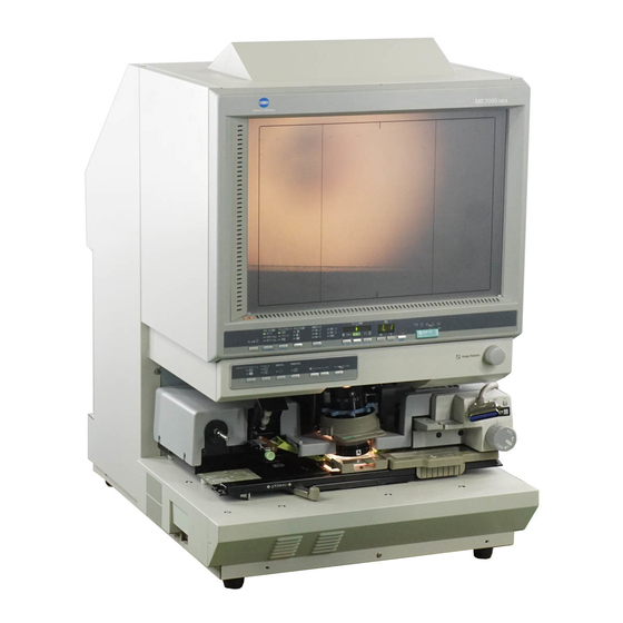
Page 29: Parts Of The Scanner
Scanner Parts of the Scanner 1. Screen: The image taken from the film is projected here for viewing. The frame on the Screen marks the data reading range. 2. Control Panel: Many operations are controlled from the keys and indicators provided here. 3. - Page 30 Scanner 9. Power Switch: Used to turn power to the unit ON and OFF. 10. Connectors: Provides connection points for the various options (Film Carrier and Controller). 11. Power Cord Socket: Plug the power cord furnished with the Scanner into this socket.
-
Page 31: Control Panel Keys And Indicators
Scanner Control Panel Keys and Indicators Control Panel 1 (Basic) Paper Selection Exposure Print Mode Print Position Paper Selection Film Type 8 ×14 Auto Text 11×17 8 ×11 Nega Fine 8 ×11 Lighter Auto Darker Posi Photo Ohter Start Memory Input Key To store one of the following functions into the memory of the Scanner, first set one of the functions on Control Panels 1 and 2 and then press this button with the head of a pen or other device. - Page 32 Scanner Lamp Illuminance Key Use to manually adjust the Projection Lamp illuminance. When the Projection Lamp is OFF, it can be turned ON again by pressing any key. Film Type Key Rotates between Auto, Nega, and Posi each time the key is pressed. Auto: The scanner automatically determines between the film type options of negative or positive for print production.
- Page 33 Scanner Paper Selection Key PC mode: Select the scanning size. When scanning the film image except standard size, the Other lamp is lit. PR mode: Selects the size of paper to be used for printing. When the printer's Paper Feeding Tray is loaded with 8-1/2" x 1" (A4) paper and the paper loaded into the Paper Cassette is 11"...
- Page 34 Scanner Multi-Print Keys Use these keys to input the desired number of prints to be made. Pressing this key increases the number of prints to be made in increments of ten (10, 20, 30 ... 90, etc.) Pressing this key increases the number of prints to be made in increments of one (1, 2, 3 ...
-
Page 35: Control Panel 1 (Shift Function)
Scanner Control Panel 1 (Shift Function) Job Recall Key When this key is pressed together with the Shift Key, the program registration locations (1J, 2J and 3J) are called. Each time this key is pressed while the Shift Key is held down, the display is switched in order of 1J →... -
Page 36: Control Panel 2
Scanner Control Panel 2 Centering Fit Masking Auto Auto Skew Masking Correction Focus Centering/Fit Key When this key is pressed, the setting rotates from OFF to the Centering and Fit functions. Auto Masking* is automatically enabled when the Centering function is selected. * Auto Masking is not enabled if Trimming is selected. - Page 37 Scanner Auto Masking Key This key is used to turn the Auto Masking function ON or OFF. The Auto Masking function will omit the frame (non-image area) of a printed film image. • The previous Centering/Fit setting is applied whenever ON is selected from the OFF state.
-
Page 38: When Misfeed/Call-Tech.-Rep. Indicator Lights Up
Scanner When Misfeed/Call-Tech.-Rep. Indicator Lights up This indicates that a paper misfeed or malfunction has occurred in the system. Check the code shown on the Multi-Print Display and perform the misfeed clearing procedure or the Call-Tech.-Rep. procedure. Misfeed Clearing Procedure Locate the misfeed using the code and perform the misfeed clearing procedure. - Page 39 Scanner After turning the power to the system OFF and unplugging its power cord from the electrical outlet, contact your Technical Representative, being sure to provide him or her with the currently displayed code (Above code). Other Malfunctions Display Code Description The power to the printer is off or there is a prob- lem with the connection of the interface cable to...
-
Page 40: Image Processing Functions
Scanner Image Processing Functions Screen Image → Print Image Description Auto Masking (1 Frame) The system masks the black bands that run along the edges of the image. Trimming (1 Frame) The system masks everything but the center of the image. Trimming (2 Frames) The system masks the frames *When 11"... - Page 41 Scanner Screen Image → Print Image Description Auto Skew Correction The unit automatically correct any skew of the image when printed. Page-by-Page Print The system takes two film images that appear side-by-side on the screen and prints them on separate 8-1/2" x 11" (A4) sheets of paper.
-
Page 42: Turning The Power On And Off
Scanner Turning the Power On and Off Turning ON Press the Power Switch of the scanner to the (ON) position. PR Mode: Press the Power Switch of the printer to the (ON) position. PC Mode: Turn on the Personal Computer. -
Page 43: Turning Off
Scanner Turning OFF Press the Power Switch of the scanner to the (OFF) position. 3-17... -
Page 44: Auto Power Save Mode
Scanner Auto Power Save Mode The unit enters the Auto Power Save mode if it is left to stand idle for a predetermined period of time. When the unit enters the Auto Power Save mode, power to the Scanner projection lamp and the printer heater is automatically shut down to save power consumption. -
Page 45: Printing Or Scanning Procedure
Scanner Printing or Scanning Procedure Here is an outline of the printing or scanning procedure: 1. Load the film The procedure for loading film is determined by the type of Film Carrier (optional) that is being used. Review the Operator's Manual that came with your Film Carrier for more information. 2. -
Page 46: Selecting A Projection Lens
Scanner Selecting a Projection Lens Projection Lenses come in the following five types. Select the one that corresponds to the film being used. Projection Lens Types TYPE1: 7.5x, 7-7.5x TYPE 2: 9-16x TYPE 3: 13-27x TYPE 4: 20-50x Sc a n ni ng Siz e F i l m 11"×17"... -
Page 47: Replacing The Projection Lens
Scanner 3.10 Replacing the Projection Lens Take hold of the Prism Holder Lever and push it up to raise the Prism Holder. Pull out the Projection Lens Unit towards the front of the Scanner. Slide the new Projection Lens Unit all the way into the Scanner along the Lens Holder Guide. -
Page 48: Positioning The Film Image
Scanner 3.11 Positioning the Film Image Marked on the Screen are the size frame markers that correspond to the scanning size. Through zooming and image rotation, and by operating the Film Carrier mounted on the system, position the image on the Screen so that the image fits in the scanning size. -
Page 49: Zooming, Focusing, And Image Rotation
Scanner 3.12 Zooming, Focusing, and Image Rotation Zooming Turn the Zooming Ring Dial (blue) to bring the image on the Screen into the print size frame. Focusing Center the image on the Screen and then press the AF (Auto Focus) Key to let the Scanner automatically bring the image into focus. - Page 50 Scanner * If the Auto Skew Correction Key is turned ON, the system will automatically correct any skew of the image when printed. 3-24...
-
Page 51: Selecting The Film Type
Scanner 3.13 Selecting the Film Type Auto The system will Nega/Posi automatically determine the polarity of the film being used when Auto is selected with the Film Type key. The system cannot determine the polarity of certain types of film. Should this occur, the film type should be selected manually. -
Page 52: Posi (Positive Film)
Scanner Posi (positive film) If positive film is to be used, Posi press the Film Type Key to select Posi. 3-26... -
Page 53: Selecting The Paper Size
Scanner 3.14 Selecting the Paper Size Selecting the Paper Size Press the Paper Selection key to select the desired print size. Each time the key is pressed, the system selects a new paper size from the currently available sizes. If the Printer is not loaded with a desired size of paper, to load paper into the printer. -
Page 54: Using The Auto Film Format Selection Function
Scanner The Auto Paper Selection function can be used only for a combination of 11" x 17" (A3) and 8-1/2" x 11" (A4) . The Page-by-Page function cannot be selected when the Auto Paper Selection capability is being used. When a 7.5x or 7-7.5x lens is being used, the Auto Paper Selection function cannot use 11"... -
Page 55: Selecting The Print Position
Scanner 3.15 Selecting the Print Position Center The system prints the image that appears in the center of the screen. Left The system makes a print of the image that appears on the left side of the screen. Page-by-Page The system prints the images that appear on both the left and right sides of the screen on separate sheets of... -
Page 56: Selecting The Image Density
Scanner 3.16 Selecting the Image Density Using Auto Exposure Press the Exposure Mode key to select the Auto Exposure mode. If the Auto Exposure setting is not satisfactory, press the appropriate Exposure Adjustment key, either Lighter or Darker, to set the desired image density. - Page 57 Scanner Press the appropriate Exposure Adjustment key, either Lighter or Darker, to set the desired image density. Press Lighter : to make the image lighter. Press Darker : to make the image darker. 3-31...
-
Page 58: Entering The Number Of Prints To Be Made
Scanner 3.17 Entering the Number of Prints to be Made 1 to 9 Enter the desired number of prints using the Multiprint Key "1". If the "1" key is pressed when "9" is shown on the Multi-Print Display, the number on the display is incremented by one: 10 → 11 →... -
Page 59: Using Auto Masking
Scanner 3.18 Using Auto Masking The Auto Masking function prevents the frame (non-image area) of a film image from appearing on the print. Selecting Auto Masking Press the Auto Masking key to turn ON this function. Operating Conditions for Auto Masking A. -
Page 60: Manual Masking Panels (Option)
Scanner 3.19 Manual Masking Panels (Option) Lengthwise Area Indication Panel Use to specify the print area in the vertical direction of the image on the Screen. The system makes a print of the image corresponding to the Area Keys lit up green. A total of 42 Area Keys are placed at 7-mm intervals. Lengthwise Area Clear Key Press to clear any print area previously defined in the vertical direction. -
Page 61: Using Manual Masking
Scanner 3.20 Using Manual Masking The optional Manual Masking Kit allows you to specify an area for printing of the displayed image through two separate features, Trimming and Masking. Selecting Trimming Press the Masking key to select (Trimming). The lights on the panel light up according to the currently selected paper size and print position. -
Page 62: Defining An Area
Scanner Defining an Area Define the end points for both the vertical and horizontal areas of the image on the screen using the green lights on the area indication panels. The points defining the vertical and horizontal area can be selected in any order. -
Page 63: Defining Page-By-Page Print Area
Scanner Defining Page-by-Page Print Area Using the vertical and horizontal points on the Area Indication Panels, define the print areas of the image on the Screen. The horizontal indicator marked A does not light up and cannot be used for defining an area. Four different areas cannot be defined on a single page. -
Page 64: Selecting Masking
Scanner Selecting Masking Press the Masking key to select (Masking) when you want to mask a given area of the image. The basic operation for manual Masking is similar to Trimming. Please refer to the previous procedures on Trimming and defining areas for instructions on performing manual Masking. -
Page 65: Using Centering And Fit
Scanner 3.21 Using Centering and Fit Once the image on the Screen has been either "manually trimmed" or "auto masked", the Image Centering function moves the image to the center of the print. The Fit function however, fits the image on the Screen onto the entire surface of the print. -
Page 66: Fit
Scanner Press the Centering/Fit key Centering/Fit to turn ON Fit. Fit mode cannot be used when the Scanner is connected the PC. 3-40... -
Page 67: Using The Cycle Print Mode
Scanner 3.22 Using the Cycle Print Mode This function automatically scans the next image following a preset period of time. Images are manually loaded onto the Carrier Glass in between cycles. This is a system setting that must be entered by an authorized Technical Representative. -
Page 68: Operating In The Cycle Print Mode
Scanner Operating in the Cycle Print Mode After entering the Cycle Print Mode, press the Start key to start. After the first scanning operation has finished, the system will automatically scan the next image following a preset period of time. The system will continue to operate until the Cycle Print Mode is canceled. -
Page 69: Selecting The Connection Mode
Scanner 3.23 Selecting the Connection Mode The Scanner connection can be selected between PR (connection to the Printer) and PC (connection to the Personal Computer). Hold down the Shift Key and the PC/PR Key together for over one second. PC mode: When the display is switched from Multi-Print to PC, the connection to the PC is valid. -
Page 70: Selecting The Resolution
Scanner 3.24 Selecting the Resolution The resolution for scanning (printing) can be selected. Press the Shift Key and the Resolution Key together. The present resolution is displayed. Press the Resolution Key while holding down the Shift Key to set the resolution. -
Page 71: Registering The Job Program
Scanner 3.25 Registering the Job Program The present setting state can be registered in up to 3 program registration locations (1J, 2J and 3J). Press the Memory Input Key Memory Input Key in the Setting mode. 1J starts blinking. To change the program registration location, press the 1 Key. -
Page 72: Calling The Job Program
Scanner 3.26 Calling the Job Program The registered Job program can be called. Press the Shift Key and the Job Recall Key together. Each time the Job Recall Key is pressed while the Shift Key is held down, the display is switched in order of 1J → 2J → 3J. When the desired setting is displayed, unhand the keys. -
Page 73: Using The Electrical Zoom
Scanner 3.27 Using the Electrical Zoom In addition to the zooming by the Lens, the Electrical Zoom function has been provided for magnifying the image when it is printed. NOTE: This function is only available on the RP mode. Zoom + When the Zoom+ key is pressed together with the Shift Key, the magnification is increased by an... -
Page 74: Skip Of Magnification
Scanner The Zoom magnification is displayed in the Multi-Print Display to 2 decimal places. The Zoom magnification level is displayed in the Exposure Display. Example:When the magnification is 0.50x, it is displayed as 50. When the magnification is 1.50x, it is displayed as 50 also. When the Zoom magnification is changed, the display is made in the Multi-Print Display as follows. -
Page 75: Clearing The Zoom Magnification
Scanner Clearing the Zoom magnification When the Zoom clr key is held down together with the Shift Key for over one second, the standard magnification is resumed. The standard magnification is fixed according to the selected paper size. Paper size 11"... -
Page 76: Adjusting The Illumination Of The Screen
Scanner 3.28 Adjusting the Illumination of the Screen The illumination of the screen can be adjusted. Press the Illumination Key to adjust the illumination of the screen. The screen is gradually darkened until it is turned OFF. When any key is pressed, the illumination returns to the maximum level. -
Page 77: Replacing The Projection Lamp
Scanner 3.29 Replacing the Projection Lamp Use the following procedure to replace the Projection Lamp whenever a reduction in brightness on the screen is detected or whenever the lamp burns out. Make sure that the replacement lamp is specified for use with this scanner. - Page 78 Scanner Remove the Projection Lamp, together with the Lamp Socket, from the Projection Lamp Unit. Unplug the Projection Lamp from the Lamp Socket. Insert a new Projection Mark Lamp so that the mark on its base is facing upwards. Make sure that the new Projection Lamp is inserted securely so that there is no gap between the Projection...
- Page 79 Scanner Insert the Projection Lamp all the way into the Lamp Holder of the Projection Lamp Unit. Slide the Projection Lamp Unit securely back into place. 3-53...
-
Page 80: System Printer (Option)
System Printer (option) System Printer (option) Parts of the Printer 1 Upper Unit Lock Release Lever: Use to open the Upper Unit. 2 Power Indicator: Light indicates when the Printer is turned ON. 3 Print Tray: Prints are output from the Printer, face down onto this tray which can hold up to 500 sheets of standard paper. - Page 81 System Printer (option) Upper Unit: Open to replace the Imaging Cartridge and to clear misfed sheets of paper. 10 Image Transfer Roller: Transfers the image onto the sheet of paper. Be careful to avoid touching it with your bare hands. 11 Fusing Unit: Permanently fixes the image onto the sheet of paper.
-
Page 82: Paper Specifications
System Printer (option) Paper Specifications Use only the following types of paper: Type Plain and recycled paper (weight 16 to 24 lbs. / 60 to 90 g/m Size Standard sizes: 11" x 17", 8-1/2" x 11", 5-1/2" x 8-1/2", A3, A4, B4, B5. Capacity Paper Feeding Tray: 5-1/2"... -
Page 83: Set The Paper
System Printer (option) Set the Paper Loading Paper into the Paper Feeding Tray Swing down the Paper Feeding Tray. Fan the paper stack thoroughly and align the edges. Load the paper stack face up in the tray and adjust the Paper Guides to secure the paper stack. -
Page 84: Loading Paper In The Paper Cassette
System Printer (option) Loading Paper in the Paper Cassette Pull the cassette out of the Printer and open the Cover. Press down the Paper Lifting Plate until it locks. Fan the paper stack thoroughly, align the edges, and place the paper in the cassette. - Page 85 System Printer (option) Close the Cover and insert the cassette into the Printer.
-
Page 86: Replacing The Toner Cartridge
System Printer (option) Replacing the Toner Cartridge Open the Upper Unit by pulling the Upper Unit Lock Release Lever forward. § Push the Print Tray in before opening the Upper Unit. Remove the old Imaging Cartridge from the printer. - Page 87 System Printer (option) Take a new Imaging Cartridge out of the box. Holding it with both hands, shake it well in the directions indicated by the arrows. Remove the seal from the Imaging Cartridge by pulling it steadily straight out. Shake the Imaging Cartridge four or five more times as shown to evenly...
- Page 88 System Printer (option) Close the Upper Unit.
-
Page 89: When The Paper Misfeed Indicator Lights Up
System Printer (option) When the Paper Misfeed Indicator Lights Up If the Misfeed Indicator lights up along with a P0 code: The size or the direction of the paper loaded in the paper tray does not match that set for the tray. Load the paper of the set size in the set direction and then open and close the Upper Unit. - Page 90 System Printer (option) Remove the sheet(s) of paper that caused the misfeed from the Paper Feeding Tray. Check that no misfed paper is left in the Printer and then reinstall the Imaging Cartridge. Close the Upper Unit. 4-11...
-
Page 91: Clearing A Misfeed From The Paper Cassette
System Printer (option) Clearing a Misfeed from the Paper Cassette Open the Upper Unit by pulling the Upper Unit Lock Release Lever forward. § Push the Print Tray in before opening the Upper Unit. Remove the Imaging Cartridge. § Be sure to cover the Imaging Cartridge with a heavy cloth to protect it from light when it is removed... -
Page 92: Clearing A Misfeed From Inside The Printer
System Printer (option) Check that no misfed paper is left in the Printer and then reinstall the Imaging Cartridge. Close the Upper Unit. Clearing a Misfeed from inside the Printer Open the Upper Unit by pulling the Upper Unit Lock Release Lever forward. - Page 93 System Printer (option) If the misfeed occurred before the sheet of paper entered the Fusing Unit, gently pull the misfed sheet up and out as shown. If the misfeed occurred after the sheet of paper entered the Fusing Unit, gently pull the misfed sheet toward you and out as shown.
-
Page 94: Solving Irregular Printing Problems
System Printer (option) Solving Irregular Printing Problems Use the following procedures to fix minor printing problems. If print quality does not improve after implementing the procedures below, contact your Technical Representative. Symptom Cause Action Light image Print density is not Change the print density properly set. -
Page 95: Miscellaneous
Miscellaneous Miscellaneous This chapter details the system specifications and initial settings as well as provides some useful tips for caring for the unit. Specifications Specifications Type: Desk-Top Type Microfilm Scanner Type of Film: Microfiche, Jackets, Aperture Cards, 16mm & 35mm Roll Film, 16mm Film Cartridges. -
Page 96: Pc Mode
Miscellaneous PC Mode Specifications Resolution: 200, 300, 400, 600, 800 dpi Output Scale: Binary, Grayscale (Option) PC Interface: SCSI-2 Standard: USA and Canada area Option: except USA and Canada area Scanning Speed: 5 sec./1 frame scanning (8-1/2" x 11" or A4 Vertical/400 dpi/AE) 4 sec./Multi-frame scanning (8-1/2"... -
Page 97: Initial Settings
Miscellaneous Initial Settings This system offers three types of settings: the user settings that are made by the user on the control panel, the settings that are made by the user using with the User Mode, and the system settings that are made by the authorized dealer. -
Page 98: User Mode
Miscellaneous User Mode User mode allows the default values of various functions to be set or changed as necessary. Setting these default values according to the need of the user saves labor in making settings again each time the power is turned ON or Panel Reset is activated. - Page 99 Miscellaneous Entering and Leaving the User Mode Hold down the Shift key and Output Selection key at the same time for 0.5 sec. The Multi-Print Display displays a “U.” Press the Exposure Adjustment key (Darker or Lighter) to select the specific function.
- Page 100 Miscellaneous Press the Clear key. This lets you leave the User mode, returning back to the ordinary mode. Settings in Each User Mode Function U1: Special Print Mode This function is not available. U2: Engineering Enhancement Mode Slight image distortion occurring in the scan direction can be corrected with this function.
- Page 101 Miscellaneous Code Setting Value Initial Setting 0.5mm 1.0mm 1.5mm 2.0mm 2.5mm 3.0mm 3.5mm 4.0mm U3: Auto Power Save Time it takes the unit to be automatically set into the Power Save mode can be set. Select U3 in the User mode. Press the Exposure Mode key to display d*.
- Page 102 Miscellaneous U4: Paper Feeding Tray Size The size and direction of the paper loaded in the Paper Feeding Tray can be set with this function. Select U4 in the User mode. Press the Exposure Mode key to display d*. Press the Exposure Adjustment key (Darker or Lighter) to select the desired setting value.
- Page 103 Miscellaneous desired setting value. Press the Start key to validate the setting value. Code Setting Value Initial Setting Turns OFF Date Print and Character Overlay functions Date Print function (upper right) Date Print function (lower right) Date Print function (upper left) Date Print function (lower left) Character Overlay function (*) (*)A personal computer and an I/F kit are necessary only when the overlay...
- Page 104 Miscellaneous U7: Imprint Mode Set Time-of-day can be corrected for the Date Print function when it becomes wrong. Select U7 in the User mode. When the Exposure Mode key is pressed, both the Exposure Display and Multi-Print Display light up steadily. In the initial condition, the year default setting is displayed.
- Page 105 Miscellaneous U8: Total Scan Counter The number of scan sequences carried out by the Scanner can be displayed with this function. Select U8 in the User mode. Press the Start key. The number of scan sequences so far carried out by the Scanner is displayed.
-
Page 106: System Settings By The Dealer
Miscellaneous System Settings by the dealer System Settings Description Selection Initial Setting Auto reset Setting changes made to the control Enabled (200V) panel that are not used within 60 Disabled (120V) seconds of being input are automatically cancelled and the system reverts back to the original settings. - Page 107 Miscellaneous System Settings Description Selection Initial Setting Contrast setting To view subtle images with standard Lighter ranges of density clearly: Light (-1 ~ -7) Normal To bring out the darker and lighter ranges of an image: Dark (+1 ~ +7) Darker The print function After a toner empty condition is...
-
Page 108: System Care
Miscellaneous System Care The system should be cleaned on a daily basis for optimal operating conditions. Cleaning the Scanner Screen With a damp cloth, clean and remove any dust or debris from the surface of the Screen. CAUTION § NEVER use alcohol or any other solvent when cleaning to avoid causing damage to the Screen or erasing the frame size markers. -
Page 109: Carrier Glass (Option)
Miscellaneous Carrier Glass (Option) With a damp cloth, clean and remove any dust or debris from the surface of the Carrier Glass. § Before cleaning the Carrier Glass, be sure to remove the Projection Lens from the Scanner. To open the Carrier Glass, pull the handle of the Microfiche Holder. -
Page 110: Cleaning The System Printer (Option)
Miscellaneous Cleaning the System Printer (Option) Clean the Printer at regular intervals. CAUTION § Use a soft cloth and NEVER use abrasives or corrosive detergents. Before cleaning the Printer, turn OFF the power and unplug the cord from the power outlet. Clean the exterior panels with a soft, dry cloth. -
Page 111: For Key Operator's Use
Miscellaneous For Key Operator’s Use When you need to call for service, the Key Operator should be prepared to provide the following information to the authorized Dealer. 1. Your Company Name, Address, Telephone Number, Department Name, Floor Number, Machine Location, etc. 2. - Page 112 konicaminolta.com 2004.6 0816-7732-01...