Table of Contents
Advertisement
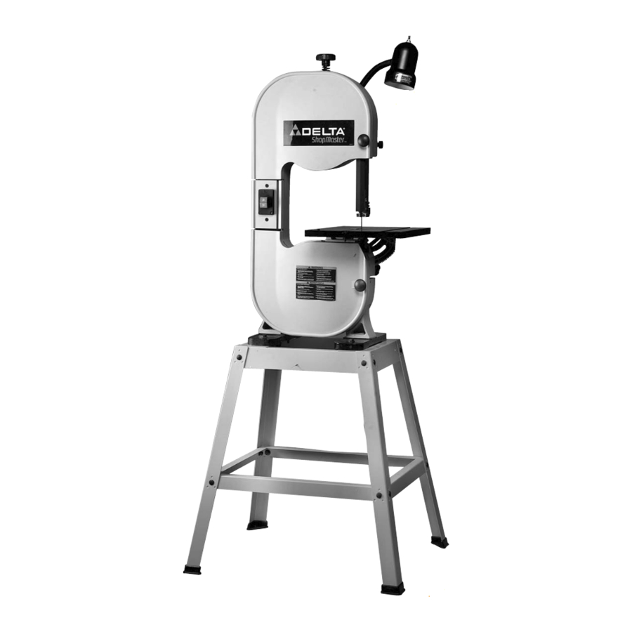
10" Band Saw
(Model BS150LS)
PART NO. A03617 - 03-17-04
Copyright © 2004 Delta Machinery
To learn more about DELTA MACHINERY
ESPAÑOL: PÁGINA 25
visit our website at: www.deltamachinery.com.
For Parts, Service, Warranty or other Assistance,
1-800-223-7278 (
1-800-463-3582).
please call
In Canada call
Advertisement
Table of Contents

Related Manuals for Delta ShopMaster BS150LS


Summary of Contents for Delta ShopMaster BS150LS
- Page 1 10" Band Saw (Model BS150LS) PART NO. A03617 - 03-17-04 Copyright © 2004 Delta Machinery To learn more about DELTA MACHINERY ESPAÑOL: PÁGINA 25 visit our website at: www.deltamachinery.com. For Parts, Service, Warranty or other Assistance, 1-800-223-7278 ( 1-800-463-3582). please call...
-
Page 2: Safety Guidelines - Definitions
If you have any questions relative to a particular application, DO NOT use the machine until you have first contacted Delta to determine if it can or should be performed on the product. - Page 3 13. USE RECOMMENDED ACCESSORIES. The use of accessories and attachments not recommended by Delta may cause damage to the machine or injury to the user. 14. USE THE PROPER EXTENSION CORD. Make sure your extension cord is in good condition. When using an extension cord, be sure to use one heavy enough to carry the current your product will draw.
-
Page 4: Additional Safety Rules For Band Saws
11. NEVER START THE MACHINE with the workpiece against the blade. 12. HOLD WORKPIECE FIRMLY against the table. DO NOT attempt to saw a workpiece that does not have a flat surface against the table. 13. HOLD WORKPIECE FIRMLY and feed into blade at a moderate speed. -
Page 5: Grounding Instructions
GROUNDING INSTRUCTIONS THIS MACHINE MUST BE GROUNDED WHILE IN USE TO PROTECT THE OPERATOR FROM ELECTRIC SHOCK. 1. All grounded, cord-connected machines: In the event of a malfunction or breakdown, grounding provides a path of least resistance for electric current to reduce the risk of electric shock. -
Page 6: Functional Description
The Delta ShopMaster Model BS150LS 10" Band Saw has a powerful 1/2 HP, ball-bearing motor for smooth performance and long life. The saw has a 7 inch depth of cut capacity. The BS150LS is supplied with a cast iron table and sturdy steel stand which provides heavy-duty support and a comfortable work height. - Page 7 BAND SAW ASSEMBLY PARTS FOR YOUR OWN SAFETY, DO NOT CONNECT THE MACHINE TO THE POWER SOURCE UNTIL THE MACHINE IS COMPLETELY ASSEMBLED AND YOU READ AND UNDERSTAND THE ENTIRE INSTRUCTION MANUAL. 1. Band Saw 2. 5mm Hex Wrench 3. 4mm Hex Wrench 4.
-
Page 8: Stand Assembly
1. Fig. 5 illustrates the four through holes (A) which will be used to secure the band saw to the stand. 2. Place the band saw on top of the stand and line up the holes (A) Fig. 5 with the holes (D) Fig. 6 on the top brackets of the stand. - Page 9 Repeat this process for the three remaining holes. 5. Push down on the top of the band saw, and make sure that all four stand feet are contacting the supporting surface. Tighten all stand hardware.
- Page 10 STEP 1. 8. Re-assemble the table tilt pinion knob (N) Fig. 15, on the back of saw so that the teeth on the pinion knob (N) engage the teeth on the trunnion (R). Fasten in place with the special screw (P) and spring using the 4mm wrench provided.
- Page 11 (D) to the cord clamps (C) Fig. 19. 3. The flexible lamp operates independently of the band saw. To turn the lamp on and off, rotate the switch (E) Fig. 19. To reduce the risk of fire, use 40 watt (or less), 120 volt, reflector track type light bulb (not supplied).
- Page 12 STARTING AND STOPPING SAW The "ON/OFF" switch is located on the front side of the band saw. To turn the saw "ON", push the button (A) Fig. 21 in to the "ON" position. To turn the saw "OFF", push the button (B) Fig. 22 in to the "OFF" position.
-
Page 13: Tracking The Blade
ADJUSTING BLADE TENSION Blades of 1/8", 1/4", and 3/8" in width by 59-1/2" in length are available for use with your band saw. NOTE: The blade tension must be adjusted to accommodate different blade widths in order to provide proper blade tracking, cutting performance, and blade life. -
Page 14: Adjusting Upper Blade Guides And Blade Support Bearing
1. Loosen the two screws (C) Fig. 27, and adjust the blade guides (D) as close as possible to the sides of the saw blade, being careful not to pinch the blade. Tighten the two screws (C). 2. Loosen screw (E) Fig. 27, and move the guide bracket (F) in or out until the front edge of the guides (D) are just behind the “gullets”... -
Page 15: Tilting The Table
(D) in or out as necessary. Tighten screw (C). 3. The lower blade support thrust bearing (E) Fig. 29 prevents the saw blade from being pushed back too far during cutting. The support bearing should be adjusted approximately 1/32" behind the blade. Loosen screw (F) Fig. - Page 16 ADJUSTING THE TABLE POSITIVE STOPS Positive stops are provided for the table at the 90 and 45 degree angle to the blade. To check and adjust the positive stops: DISCONNECT MACHINE FROM POWER SOURCE. 1. Tilt the table to the 90 degree position as shown in Fig.
-
Page 17: Changing Blades
1. Pull door latches (A) Fig. 35 and open doors (B). 2. Loosen the two screws (C) Fig. 36, and remove the blade guard (D). 3. To release tension on the band saw blade loosen screw (E) and turning tension knob (G) Fig. 35 counterclockwise. -
Page 18: Cutting Curves
When withdrawing the piece being cut, changing the cut, or for any other reason, be careful not to accidentally draw the blade off the wheels. In most cases, it is easier and safer to turn the stock and saw out through the waste material, rather than try to withdraw the stock from the blade. - Page 19 Fig. 41 Fig. 41 illustrates a typical bevel cutting operation using the accessory miter gage. Fig. 42 Fig. 42 illustrates a typical resawing application using the accessory rip fence.
-
Page 20: Troubleshooting Guide
TROUBLESHOOTING GUIDE In spite of how well a band saw is maintained, problems can occur. The following troubleshooting guide will help you solve the more common problems: Trouble: SAW WILL NOT START. Probable Cause 1. Saw not plugged in. 2. Fuse blown or circuit breaker tripped. - Page 21 3. Blade support bearing improperly adjusted. 4. Blade wheel not tracking properly. 5. Bad weld on blade. 6. Worn tires. Trouble: BAND SAW MAKES UNSATISFACTORY CUTS. Probable Cause 1. Blade not tensioned properly. 2. Blade guides improperly adjusted. 3. Blade support bearing improperly set.
-
Page 22: Band Saw Blades
A band saw blade is a delicate piece of steel that is subjected to tremendous strain. You can obtain long use from a band saw blade if you use it properly. Use blades of proper thickness, width and temper for the various types of material and cuts. - Page 23 NOTES...
-
Page 24: Maintenance
Two Year Limited New Product Warranty Delta will repair or replace, at its expense and at its option, any new Delta machine, machine part, or machine accessory which in normal use has proven to be defective in workmanship or material, provided that the customer returns the product prepaid to a Delta factory service center or authorized service station with proof of purchase of the product within two years and provides Delta with reasonable opportunity to verify the alleged defect by inspection. - Page 25 Phone: (604) 420-0102 Fax: (604) 420-3522 The following are trademarks of PORTER-CABLE • DELTA (Las siguientes son marcas registradas de PORTER-CABLE • DELTA S.A.) (Les marques suivantes sont des marques de fabriquant de la PORTER-CABLE • DELTA): Auto-Set Contractor’s Saw II™, Delta ®...