Table of Contents
Advertisement
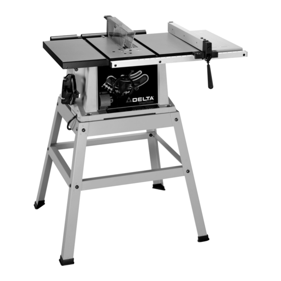
10" Table Saw
(Model TS220LS)
PART NO. 905579 - 03-24-04
Copyright © 2004 Delta Machinery
To learn more about DELTA MACHINERY
ESPAÑOL: PÁGINA 29
visit our website at: www.deltamachinery.com.
For Parts, Service, Warranty or other Assistance,
1-800-223-7278 (
1-800-463-3582).
please call
In Canada call
Advertisement
Table of Contents

Related Manuals for Delta (Model TS220LS)


Summary of Contents for Delta (Model TS220LS)
- Page 1 10" Table Saw (Model TS220LS) PART NO. 905579 - 03-24-04 Copyright © 2004 Delta Machinery To learn more about DELTA MACHINERY ESPAÑOL: PÁGINA 29 visit our website at: www.deltamachinery.com. For Parts, Service, Warranty or other Assistance, 1-800-223-7278 ( 1-800-463-3582). please call...
-
Page 2: Safety Guidelines - Definitions
SAFETY GUIDELINES - DEFINITIONS This manual contains information that is important for you to know and understand. This information relates to protect- ing YOUR SAFETY and PREVENTING EQUIPMENT PROBLEMS. To help you recognize this information, we use the symbols to the right. Please read the manual and pay attention to these sections. Indicates an imminently hazardous situation which, if not avoided, will result in death or serious injury. - Page 3 GENERAL SAFETY RULES FAILURE TO FOLLOW THESE RULES MAY RESULT IN SERIOUS INJURY. 1. FOR YOUR OWN SAFETY, READ THE INSTRUCTION MANUAL BEFORE OPERATING THE MACHINE. Learning the machine’s application, limitations, and specific hazards will greatly minimize the possibility of accidents and injury.
-
Page 4: Additional Safety Rules For Table Saws
15. NEVER have any part of your body in line with the path of the saw blade. 16. NEVER REACH AROUND or over the saw blade. 17. NEVER attempt to free a stalled saw blade without first turning the machine “OFF”. 18. PROPERLY SUPPORT LONG OR WIDE workpieces. -
Page 5: Power Connections
3. 240 VOLT SINGLE PHASE OPERATION: The motor supplied with your saw is a dual voltage, 120/240 volt motor. If it is desired to operate your saw at 240 volts, single phase, it is necessary to reconnect the motor leads in the motor junction box by following the in- structions given on the motor nameplate. -
Page 6: Extension Cords
It is also necessary to replace the 120 volt plug, supplied with the motor, with a UL/CSA Listed plug suitable for 240 volts and the rated current of the saw as illustrated in Fig. C. Contact your local Authorized Delta Service Center or qualified electrician for proper procedures to install the plug. -
Page 7: Functional Description
- the most powerful in its class. This saw is designed to give high quality performance with depth of cut capacity up to 3" (76mm) at 90° and 2" (51mm) at 45° for clean cutting of standard stock sizes. This package includes the saw, a metal stand, rip fence, miter gage, see-through blade guard with splitter and anti-kickback fingers, a 10”... - Page 8 6 - Rip Fence 7 - Wrenches for Blade Changing 8 - M8x1.25 Hex Nut for Rip Fence 9 - Locking Handle for Rip Fence 10 - Fence Rail 11 - Blade Raising and Lowering Handwheel 12 - M6x1x12mm Flat Head Screw for Mounting Blade Raising and Lowering Handwheel 13 - Handle for Blade Raising and Lowering Handwheel...
- Page 9 STAND PARTS 49 - Leg (4) 50 - 3/8” Flat Washer for Mounting Saw to Stand & for Assembling Stand (24) 51 - Foot (4) 52 - M8x1.25 Hex Nut for Mounting Saw to Stand & for Assembling Stand (20) 53 - M8x1.25x40mm Hex Screw for Mounting Saw to Stand (4)
-
Page 10: Stand Assembly
3. Then, turn saw table face up, as shown in Fig. 4B (Saw is shown fully assembled here). 3. Push down on top of the saw so the legs of the stand adjust to the surface of the floor and tighten all stand hardware and hardware which secures saw to stand. - Page 11 ASSEMBLING BLADE RAISING AND LOWERING HANDWHEEL 1. Insert M6x1x55mm cheese head screw (14) Fig. 3, through handle (E) Fig. 5 and assemble handle (E) to handwheel (A) by threading screw (D) Fig. 5 clockwise into handwheel. 2. Fig. 6, illustrates the handle (E) assembled to handwheel (A).
- Page 12 POWER SOURCE. 1. IMPORTANT: THE BLADE GUARD AND SPLITTER ASSEMBLY MUST BE PROPERLY ALIGNED TO THE SAW BLADE IN ORDER TO PREVENT KICKBACK. 2. Position the blade 90 degrees to the table and lock in place. 3. Fasten the splitter support bracket (A) Fig. 9, to splitter bracket (B) using two 1/4-20 x 1/2"...
- Page 13 (H). 9. Using a straight edge, check to see if the splitter (H) Fig. 16, is aligned with the saw blade (R). If an adjustment is necessary, the splitter (H) can be moved left or right and rotated.
-
Page 14: Extension Wing
EXTENSION WING 1. Assemble extension wing (A) Fig. 18, to the saw table using three 1/4-20 x 5/8” hex head screws (B), 1/4" lockwashers (C), and 1/4" flat washers (D). 2. With a straight edge (E) Fig. 19, make certain the top, front and rear edges of the extension wing (A) are level with the saw table before tightening three screws which secure extension wing to saw table. -
Page 15: Rip Fence
4. The rip fence is usually operated on the right hand side of the saw table. Lift lock handle (B) Fig. 24, and position fence on table as shown. Push downward on handle (B) Fig. 24, to lock fence in place on saw table. - Page 16 2. Assemble the miter gage holder (A) Fig. 28, to the left side of the saw cabinet using the four M4.2x10mm pan head screws (B) Fig. 29, and 3/16" washers (C) from inside saw cabinet.
- Page 17 OUTFEED SUPPORT 1. Loosely fasten both brackets (A) Fig. 31, to the bottom left side of the saw table as shown, using two M6x1x15mm head screws lockwashers (C). Assemble two remaining brackets to the bottom right side of saw table in the same manner.
-
Page 18: Overload Protection
STARTING AND STOPPING SAW 1. The on/off switch is located underneath the switch shield (A) Fig. 36. To turn the saw “ON”, move switch trigger (B) up to the “ON” position. 2. To turn the saw “OFF”, push down on switch shield (A) Fig. -
Page 19: Blade Tilting Control
CUTTING OPERATIONS. ADJUSTING 90 AND 45 DEGREE POSITIVE STOPS Your saw is equipped with positive stops for rapid and accurate positioning of the saw blade at 90 and 45 degrees to the table. To adjust the positive stops, proceed as follows: DISCONNECT MACHINE FROM POWER SOURCE. -
Page 20: Rip Fence Operation And Adjustments
ORDER TO HELP PREVENT KICKBACK WHEN RIPPING. 4. The saw blade is set parallel to the miter gage slot at the factory and the fence must be parallel to the miter gage slot in order to do accurate work and prevent kickback when ripping. -
Page 21: Changing The Blade
2. Raise the blade to its highest position and adjust the blade so it is 90 degrees to the table. 3. Select a tooth on the saw blade that is set to the left. Mark this tooth with a pencil or marker. - Page 22 Start the cut slowly and hold the work firmly against the miter gage and the table. One of the rules in running a saw is that you never hang onto or touch a free piece of work. Hold the supported piece, not the free piece that is cut off.
- Page 23 1. Start the motor and advance the work holding it down and against the fence. Never stand in the line of the saw cut when ripping. Hold the work with both hands and push it along the fence and into the saw blade (Fig. 50).
- Page 24 Fig. 55. The saw and cutter overlap is shown in Fig. 56, (A) being the outside saw, (B) an inside cutter, and (C) a paper washer or washers, used as needed to control the exact width of groove.
- Page 25 2. Attach the dado head set (D) Fig. 57, to the saw arbor. NOTE: THE OUTSIDE ARBOR FLANGE CAN NOT BE USED WITH THE DADO HEAD SET, TIGHTEN THE ARBOR NUT AGAINST THE DADO HEAD SET BODY. DO NOT LOSE THE OUTSIDE ARBOR FLANGE. IT WILL BE NEEDED WHEN REATTACHING A BLADE TO THE ARBOR.
-
Page 26: Constructing A Featherboard
CONSTRUCTING A FEATHERBOARD Fig. 59, illustrates dimensions for making a typical featherboard. The material which the featherboard is constructed of, should be a straight piece of wood that is free of knots and cracks. Featherboards are used to keep the work in contact with the fence and table and help prevent kickbacks. -
Page 27: Constructing A Push Stick
CONSTRUCTING A PUSH STICK When ripping work less than 4 inches wide, a push stick should be used to complete the feed and could easily be made from scrap material by following the pattern shown in Fig. 61. Fig. 61... -
Page 28: Parts, Service Or Warranty Assistance
A complete line of accessories is available from your Delta Supplier, Porter-Cable • Delta Factory Service Centers, and Delta Authorized Service Stations. Please visit our Web Site for the name of your nearest supplier. Since accessories other than those offered by Delta have not been tested with this product, use of such accessories could be hazardous. - Page 29 Phone: (604) 420-0102 Fax: (604) 420-3522 The following are trademarks of PORTER-CABLE • DELTA (Las siguientes son marcas registradas de PORTER-CABLE • DELTA S.A.) (Les marques suivantes sont des marques de fabriquant de la PORTER-CABLE • DELTA): Auto-Set Contractor’s Saw II™, Delta ®...