Table of Contents
Advertisement
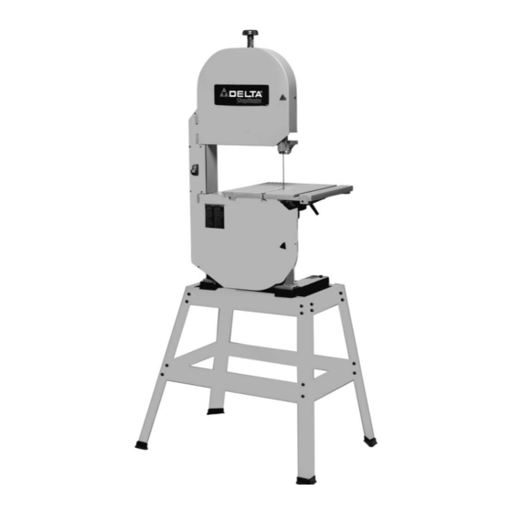
12" Band Saw
(Model BS220LS)
PART NO. 909507 - 12-23-02
Copyright © 2002 Delta Machinery
To learn more about DELTA MACHINERY
ESPAÑOL: PÁGINA 21
visit our website at: www.deltamachinery.com.
For Parts, Service, Warranty or other Assistance,
1-800-223-7278 (
1-800-463-3582).
please call
In Canada call
Advertisement
Table of Contents

Related Manuals for Delta ShopMaster BS220LS


Summary of Contents for Delta ShopMaster BS220LS
- Page 1 12" Band Saw (Model BS220LS) PART NO. 909507 - 12-23-02 Copyright © 2002 Delta Machinery To learn more about DELTA MACHINERY ESPAÑOL: PÁGINA 21 visit our website at: www.deltamachinery.com. For Parts, Service, Warranty or other Assistance, 1-800-223-7278 ( 1-800-463-3582). please call...
-
Page 2: General Safety Rules
If you have any questions relative to a particular application, DO NOT use the machine until you have first contacted Delta to determine if it can or should be performed on the product. -
Page 3: Save These Instructions
17. REDUCE THE RISK OF UNINTENTIONAL STARTING. 21. NEVER LEAVE TOOL RUNNING UNATTENDED. Make sure switch is in “OFF” position before plugging in TURN POWER OFF. Don’t leave tool until it comes to a power cord. In the event of a power failure, move switch complete stop. -
Page 4: Power Connections
POWER CONNECTIONS A separate electrical circuit should be used for your machines. This circuit should not be less than #12 wire and should be protected with a 20 Amp time lag fuse. If an extension cord is used, use only 3-wire extension cords which have 3- prong grounding type plugs and matching receptacle which will accept the machine’s plug. -
Page 5: Extension Cords
FOREWORD The Delta ShopMaster Model BS220LS 12" Band Saw has a powerful 1/2 HP, induction motor for smooth performance and long life. The BS220LS is supplied with a sturdy steel stand which provides heavy-duty support and a comfortable work height. -
Page 6: Table Of Contents
BAND SAW PARTS Fig. 2 1. Band Saw 10. Table Assembly 2. 12¾" Upper Brace (2) 11. Plastic Foot (4) 3. 21½" Upper Brace (2) 12. M8x1.25x70mm Hex Socket Head Screw (1) 4. 17" Lower Brace (2) 13. M8x1.25x45mm Hex Head Screw (4) 5. -
Page 7: M8X1.25 Hex
ASSEMBLY FOR YOUR OWN SAFETY, DO NOT CONNECT THE MACHINE TO THE POWER SOURCE UNTIL THE MACHINE IS COMPLETELY ASSEMBLED AND YOU READ AND UNDERSTAND THE ENTIRE INSTRUCTION MANUAL. STAND 1. Assemble stand as shown in Fig. 3, using parts shown in Fig. -
Page 8: M8X1.25X45Mm Hex Head
3. Place a M8.4 flat washer onto a M8x1.25x45mm hex head screw. Insert the screw through the hole (D) Fig. 6, in the stand and thread screw into the tapped hole in the band saw and tighten securely. Repeat this process for the remaining hole in stand and threaded hole in the band saw and tighten securely. - Page 9 4. Place a M6.4 flat washer (B) Fig. 10, onto a M6x1x30mm cheese head screw (A), and insert screw slot in table. Thread a M6x1 wing nut (C) Fig. 10, onto the screw and tighten securely. Fig. 10 UPPER BLADE GUIDE ASSEMBLY Fasten the upper blade guide assembly (A) Fig.
-
Page 10: Adjusting Blade Tension
OPENING AND CLOSING HINGED DOOR When making adjustments such as changing the blade, tracking the blade, blade guide adjustments, etc., the hinged doors (A) and (B) Figs. 15 and 16, can be opened as follows: NEVER OPEN THE HINGED DOOR WHEN THE MACHINE IS RUNNING. -
Page 11: Tracking The Blade
TRACKING THE BLADE For accurate work and maximum blade life, it is important that the blade (A) Fig. 18, be centered on the upper band saw wheel. When this adjustment is properly made, the blade will “track” – that is, it will run steady in the same line. -
Page 12: Lower
ADJUSTING UPPER BLADE GUIDES AND BLADE SUPPORT BEARING The blade guides must be properly adjusted to prevent the blade from twisting during operation. The upper blade guides and blade support bearing should be adjusted only after the blade is tensioned and tracking properly. -
Page 13: Tilting The Table
2. The lower blade guides are held in the guide bracket with set screws (D) Fig. 24. Loosen set screws (D) and adjust blade guides as close as possible to the sides of the saw blade, being careful not to pinch the saw blade. Then tighten set screws (D). -
Page 14: Changing Blades
MAINTENANCE ADJUSTING BELT TENSION If the drive belt on your band saw is slipping, check and adjust as follows: DISCONNECT MACHINE FROM POWER SOURCE. 1. Remove screw (A) Fig. 29, and belt and pulley cover (B). 2. A poly V-belt (C) Fig. 30, drives the saw pulley (D) from the motor pulley (E). -
Page 15: Dust Chute
DUST CHUTE A dust chute (A) Fig. 33, is provided which enables you to connect your band saw to a standard shop vacuum or dust collector. The opening of the dust chute is 2-1/4" I.D. Fig. 33 OPERATING THE BAND SAW Before starting the machine, insure that all adjustments are properly made and the guards are in place. -
Page 16: Troubleshooting Guide
TROUBLESHOOTING GUIDE In spite of how well a band saw is maintained, problems can occur. The following troubleshooting guide will help you solve the more common problems: Trouble: SAW WILL NOT START. Probable Cause Remedy 1. Saw not plugged in. 1. - Page 17 TROUBLESHOOTING GUIDE (CONTINUED) Trouble: BLADE WILL NOT TRACK. Probable Cause Remedy 1. Blade too loose 1. Adjust tension 2. Upper wheel not properly adjusted. 2. Adjust upper wheel. 3. Improperly adjusted blade support bearing. 3. Adjust blade support bearing. Trouble: CUT DOES NOT AGREE WITH SETTING ON THE TILT SCALE. Probable Cause Remedy 1.
-
Page 18: Band Saw Blades
This will save blades and will produce better cuts. For cutting wood and similar materials, Delta offers blades in widths of 1/8", 3/16", 1/4", 3/8", and 1/2". Any one of a number of conditions may cause a band saw blade to break. Blade breakage is, in some cases, unavoidable, being the natural result of the peculiar stresses to which blades are subjected. - Page 19 NOTES...
- Page 20 Two Year Limited Warranty Delta will repair or replace, at its expense and at its option, any Delta machine, machine part, or machine accessory which in normal use has proven to be defective in workmanship or material, provided that the customer returns the product prepaid to a Delta factory service center or authorized service station with proof of purchase of the product within two years and provides Delta with reasonable opportunity to verify the alleged defect by inspection.
- Page 21 Delta Distributor, Authorized · Service Center, or Porter-Cable Delta Factory Service Center. If you do not have access to any of these, call 800-223-7278 and you will · be directed to the nearest Porter-Cable Delta Factory Service Center. Las Estaciones de Servicio Autorizadas están ubicadas en muchas grandes ciudades.