Table of Contents
Advertisement
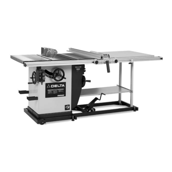
Limited Edition Unisaw
Limited Edition Unisaw
50" Commercial Biesemeyer
To learn more about DELTA MACHINERY
visit our website at: www.deltamachinery.com.
For Parts, Service, Warranty or other Assistance,
1-800-223-7278 (
please call
52" Unifence
Fence System
78-995 (50") Biesemeyer Fence Assembly
1-800-463-3582).
In Canada call
with
®
(Model 36-841)
36-841 Consists of:
36-829 Base Unit
36-937 10" Cast Iron Wings(2)
36-918 (52") Unifence Assembly
36-978 Gray table boards
36-904 Unifence Front Rail with Stop
35-617 Carbide Blade
50-289 Mobile Base
36-862 Zero Clearance Insert
with
®
(Model 36-843)
36-843 Consists of:
36-829 Base Unit
36-937 10" Cast Iron Wings(2)
78-996 Commercial Fence with Legs
78-924 Gray table boards
35-617 Carbide Blade
50-289 Mobile Base
36-862 Zero Clearance Insert
PART NO. 422-04-651-0063 (01-15-02)
Copyright © 2002 Delta Machinery
®
Advertisement
Table of Contents

Related Manuals for Delta Unisaw 36-841


Summary of Contents for Delta Unisaw 36-841
- Page 1 Limited Edition Unisaw Limited Edition Unisaw 50" Commercial Biesemeyer To learn more about DELTA MACHINERY visit our website at: www.deltamachinery.com. For Parts, Service, Warranty or other Assistance, 1-800-223-7278 ( please call 52" Unifence (Model 36-841) 36-937 10" Cast Iron Wings(2) 36-918 (52") Unifence Assembly...
-
Page 2: General Safety Rules
If you have any questions relative to a particular application, DO NOT use the machine until you have first contacted Delta to determine if it can or should be performed on the product. -
Page 3: Additional Safety Rules For Circular Saws
KICKBACK FINGERS except when otherwise directed in the manual. 7. REMOVE CUT-OFF PIECES AND SCRAPS from the table before starting the saw. The vibration of the machine may cause them to move into the saw blade and be thrown out. After cutting, turn the machine off. -
Page 4: Motor Specifications
A separate electrical circuit should be used for your machines. This circuit should not be less than #12 wire and should be protected with a 20 Amp time lag fuse. If an extension cord is used, use only 3-wire extension cords which have 3- prong grounding type plugs and matching receptacle which will accept the machine’s plug. -
Page 5: Extension Cords
After cleaning, cover the unpainted surfaces with a good quality household floor paste wax. Figures 1 and 2, illustrate the saw and all loose items supplied with the machine. Figs. 3, 4, and 5, illustrate the items supplied with the fence system. - Page 6 UNISAW 1. Unisaw 2. Switch 3. Motor cover 4. Blade guard and splitter bracket 5. Support rod 6. 5/8" Internal tooth washer 7. 5/8-18 Jam nut 8. Upper bracket for splitter 9. Lower bracket for support rod 10. 5/16" l.D. Flat washers (2) 11.
- Page 7 1. Unifence body (1) 2. Fence (1) 3. Leg/Shelf support bracket 4. Legs (2) 5. Table support brackets (2) 6. Unifence cursor (1) 7. Unifence guide rail (1) 8. #8 x 7/8" wood screws (19) 9. Z brackets (3) 10. Angle brackets (3) 12.
- Page 8 12 - Lock washers (2) Fig. 4 LIMITED EDITION UNISAW ASSEMBLY WARNING: FOR YOUR OWN SAFETY, DO NOT CONNECT THE SAW TO THE POWER SOURCE UNTIL THE SAW IS COMPLETELY ASSEMBLED AND YOU READ AND UNDERSTAND THE ENTIRE INSTRUCTION MANUAL. ASSEMBLING BLADE...
- Page 9 (D), flat washer (E), and hex nut (F) through hole (G). 3. Attach the side of switch bracket (A) Fig. 10B, to the inside of extension table at the front of the saw using the 7/16-20x1-1/4" screw and flat washer (C). Tighten screws (C) and (D).
-
Page 10: Assembling Blade Guard And Splitter Assembly
“REMOVING THE SAW BLADE”. - Page 11 Fig. 17 6. Using a wrench to hold the hex nut (J) Fig. 16, tight- en rod (G) Fig. 17, with a small screwdriver (K) or similar device through the hole in the end of the rod as shown. 7. Assemble lower bracket (L) Fig. 18, to rod (G) and loosely tighten with two one-inch long hex head screws (S) and lockwashers from underneath bracket (L).
- Page 12 Fig. 23 11. Reassemble the saw blade, making certain the teeth are pointing down at the front of the saw table as shown in Fig. 23, and assemble the outside blade flange and arbor nut (X). With open end wrench (Y) on the flats of the arbor to keep it from turning, tighten arbor nut by turning box end wrench (Z) counterclockwise.
-
Page 13: Motor Cover
Align the four holes in the dust chute adapter (A) Fig. 32B,with the four holes in the back of the saw cabinet (B) and attach the dust chute adapter with four #10 x 1/2" sheet metal screws. NOTE:... - Page 14 ASSEMBLY INSTRUCTIONS FOR MODEL 36-918 52" UNIFENCE WITH 34-978 TABLE AND SHELF 1. Fig. 33 shows the hole location for mounting the Unifence table legs to the table board. 2. Lay the table upside down on the floor or bench, as shown in Fig.
- Page 15 NOTE: Using a square (M) Fig. 41, make certain that Z-brackets (J) are perpendicular to the saw table as shown. Also, lift upward on Z-brackets while tightening screws to eliminate any play. 8. Fig. 42, illustrates Z-brackets (J) properly assembled to extension wing.
-
Page 16: Assembling Unifence Guide Rail To Table
13. Using a straight edge (S) Fig. 46, make certain the Unifence table surface is level with the saw table by placing a square (S) Fig. 46 on the table board and the extension wing, and then adjust the brackets (N) Fig. - Page 17 Fig. 49 3. Insert two 3/8-24x1" hex head bolts into the two holes (F) Fig. 49, in the front of saw table and place flat washer and nut onto bolt from underneath the saw table. Screw bolts into nuts two full turns, leaving bolt head extended approximately 1/2"...
- Page 18 8. Move the square (H) Fig. 54, to the end of the Unifence table and check to make certain the same distance is maintained from the top surface of the extension table (K) to the top surface of the guide rail (C). Move the front table support (L) Fig.
-
Page 19: Assembling Unifence Body To Guide Rail
Fig. 60 ASSEMBLING CURSOR TO UNIFENCE BODY 1. Remove two screws and flat washers (A) Fig. 60, and assemble the cursor (B) to the Unifence body (C). Replace the two screws and flat washers (A). 2. Fig. 61 illustrates the cursor (B) assembled to the Unifence body. -
Page 20: Assembling Fence To Unifence Body
Fig. 66 ASSEMBLING FENCE TO UNIFENCE BODY 1. The fence (A) can be assembled to clamp plate (B) in either the horizontal position as shown in Fig. 66, or the vertical position as shown in Fig. 67. Make certain the two lock knobs, one of which is shown at (C), are loose and slide fence (A) onto clamp plate (B) as shown. -
Page 21: Ripping With The Unifence
Never stand in the line of the saw cut when ripping. Hold the work with both hands and push it along the fence and into the saw blade as shown in Fig. 74. The work can then be fed through the saw blade with one or two hands. After the work is beyond the saw blade and anti-kickback fingers, the hand is removed from the work. -
Page 22: Adjusting Fence Parallel To Miter Gage Slots
pushboard can be made as shown in Fig. 124A.When ripping material with a veneer facing that extends over the material, the fence (A) should be in the horizontal position with the veneer (B) extending over the lip of the fence, as shown in Fig. - Page 23 (B) and lock knobs (C) so that the fence (A) will be attached to the right side of the fence body, as shown in Fig. 83. The complete fence assembly (D) Fig. 83, can easily be moved to the left side of the saw table. necessary. Fig. 80 Fig.
-
Page 24: Using The Fence As Acut-Off Gage
Fig. 84 USING THE FENCE AS A CUT-OFF GAGE WARNING: WHEN USING YOUR UNIFENCE AS A CUT-OFF GAGE, MAKE SURE IT IS PROPERLY SET UP AS DESCRIBED HERE. The fence can be used as a cut-off gage when cross cutting a number of pieces to the same length. IMPORTANT: When using the fence as a cut-off gage, it is very important that the rear end of the fence be positioned so the work piece is clear of the fence before... - Page 25 ASSEMBLY INSTRUCTIONS FOR MODEL 78-995 50" COMMERCIAL BIESEMEYER FENCE SYSTEM ASSEMBLING GUIDE RAILS 1. Assemble the front rail (A) Fig. 88, to front of saw table using the two 3/8-16 x 1-1/4" long flat head Phillips screws (B), 7/8" flat washers, lockwashers and 3/8-16 hex nuts supplied.
- Page 26 Make sure end of table (N) is flush against extension wing (P). Using a straight edge make sure table (N) is in the same plane and level with saw table (P). Lightly tap table up or down and adjust leveling screws (R) Fig.
- Page 27 ASSEMBLING GUIDE TUBE TO FRONT RAIL 1. Lay the guide tube (B) Fig. 97, on the saw table as shown, and line up the threaded holes (C) on bottom of guide tube (B) with the through holes (D) on the front rail (A).
-
Page 28: Adjusting Clamping Action Of Fence Locking Handle
ADJUSTING FENCE PARALLEL TO MITER GAGE SLOTS NOTE: Delta table saws have been aligned at the factory so that the miter gage slots in the table are parallel with the saw blade. It is recommended, however, to check and make certain this alignment is correct before adjust- ing the fence parallel to the miter gage slot as follows: The fence (A) Fig. -
Page 29: Starting And Stopping The Saw
(A), clockwise. To lower the saw blade, turn handwheel (A) counterclockwise. The saw blade is locked at any height by turning the lock knob (B) Fig. 108, clockwise. Due to the wedge action of this locking device, only a small amount of force is required to lock the blade raising mechanism securely. -
Page 30: Adjusting Table
DISCONNECT MACHINE FROM POWER SOURCE. 1. Raise the saw blade all the way to the top and turn the blade tilting handwheel clockwise as far as it will go. 2. Using a square, check to see if the blade is 90 degrees to the table. -
Page 31: Adjusting Table Insert
ADJUSTING TABLE INSERT Place a straight edge (B) across the table at both ends of the table insert as shown in Fig. 113. The table insert (A) should always be level with the table. If an adjustment is necessary, turn the adjusting screws (C), as needed, with allen wrench supplied. -
Page 32: Maintenance
4. Place the open end wrench (B) Fig. 117, on the flats of the saw arbor to keep the arbor from turning, and using wrench (A), turn the arbor nut (C) clockwise. Remove arbor nut, blade flange and saw blade. - Page 33 The following information describes the safe and proper method for performing the most common sawing operations. NOTE: THE USE OF ATTACHMENTS AND ACCESSORIES NOT RECOMMENDED BY DELTA MAY RESULT IN THE RISK OF INJURY TO PERSONS.
- Page 34 Start the motor and advance the work holding it down and against the fence. Never stand in the line of the saw cut when ripping. Hold the work with both hands and push it along the fence and into the saw blade as shown in Fig.
-
Page 35: Using Accessory Moulding Cutterhead
Loosen screws (G) and (H) Fig. 126. Lift up and swing blade guard and splitter assembly (W) Fig. 127, to the rear of the saw, and then tighten screws (G) and (H). CAUTION: Always return and fasten the blade guard and splitter assembly to its proper operating position for normal thru-sawing operations. -
Page 36: Using Accessory Dado Head
Fig. 131. The saw and cutter overlap is shown in Fig. 132, (A) being the outside saw, (B) an inside cutter, and (C) a paper washer or washers which can be used as needed to control the exact width of groove. -
Page 37: Constructing A Featherboard
Splitter and Anti-kickback Fingers Fig. 137, is an accessory that can be used in place of the standard blade guard that is supplied with the Unisaw. The Delta Model 34-976 Uniguard Blade Guard can be mounted to the Unisaw, the Unisaw with a Jet-Lock rip fence, the Unisaw with a 52"... -
Page 38: Constructing A Push Stick
CONSTRUCTING A PUSH STICK When ripping work less than 4 inches wide, a push stick should be used to complete the feed and could easily be made from scrap material by following the pattern shown. -
Page 39: Parts, Service Or Warranty Assistance
1-800-223-7278 (In Canada call 1-800-463-3582). Delta will repair or replace, at its expense and at its option, any Delta machine, machine part, or machine accessory which in normal use has proven to be defective in workmanship or material, provided that the customer returns the product prepaid to a Delta factory service center or authorized service station with proof of purchase of the product within two years and provides Delta with reasonable opportunity to verify the alleged defect by inspection. - Page 40 Parts and accessories for Porter-Cable ·Delta products should be obtained by contacting any Porter-Cable·Delta Distributor, Authorized Service Center, or Porter-Cable·Delta Factory Service Center. If you do not have access to any of these, call 800-223-7278 and you will be directed to the nearest Porter-Cable·Delta Factory Service Center. Las Estaciones de Servicio Autorizadas están ubicadas en muchas grandes ciudades.