Table of Contents
Advertisement
Advertisement
Table of Contents

Related Manuals for MSI 865GM2-LS - Motherboard - Micro ATX


Summary of Contents for MSI 865GM2-LS - Motherboard - Micro ATX
- Page 1 865GM2 / 865PEM2 MS-6743 (v1.X) Micro ATX Mainboard Version 1.1 G52-M6743X4...
-
Page 2: Fcc-B Radio Frequency Interference Statement
Manual Rev: 1.1 Release Date: May 2003 FCC-B Radio Frequency Interference Statement This equipment has been tested and found to comply with the limits for a class B digital device, pursuant to part 15 of the FCC rules. These limits are designed to provide reasonable protection against harmful interference when the equip- ment is operated in a commercial environment. -
Page 3: Copyright Notice
Copyright Notice The material in this document is the intellectual property of MICRO-STAR INTERNATIONAL. We take every care in the preparation of this document, but no guarantee is given as to the correctness of its contents. Our products are under continual improvement and we reserve the right to make changes without notice. -
Page 4: Safety Instructions
Safety Instructions Always read the safety instructions carefully. Keep this User’s Manual for future reference. Keep this equipment away from humidity. Lay this equipment on a reliable flat surface before setting it up. The openings on the enclosure are for air convection hence protects the equipment from overheating. -
Page 5: Table Of Contents
Safety Instructions ..................v Chapter 1. Getting Started ................ 1-1 Mainboard Specifications ..............1-2 Mainboard Layout ................1-4 MSI Special Features ................1-5 Live BIOS™/Live Driver™ ............1-5 Live Monitor™ ................1-6 PC Alert™ 4 ................... 1-7 Chapter 2. Hardware Setup ............... 2-1 Quick Components Guide .............. - Page 6 USB Connectors ................2-12 VGA Connector ................2-13 Audio Port Connectors ............... 2-13 IEEE1394 Port (Optional) ............2-14 Serial Port Connectors: COMA/B ..........2-14 Parallel Port Connectors: LPT1 ............ 2-15 Connectors ..................2-16 Front Disk Drive Connector: FDD1 ..........2-16 Hard Disk Connectors: IDE1 &...
- Page 7 Getting Help .................. 3-3 The Main Menu ................... 3-4 Standard CMOS Features ..............3-6 Advanced BIOS Features ..............3-9 Advanced Chipset Features ............... 3-13 Integrated Peripherals ................ 3-16 Power Management Setup ..............3-23 PNP/PCI Configurations ..............3-27 PC Health Status ................3-29 Frequency/Voltage Control ..............
-
Page 8: Chapter 1. Getting Started
Getting Started Chapter 1. Getting Started Getting Started Thank you for purchasing the MS-6743 v1.X M-ATX mainboard. The MS-6743 is based on Intel Springdale-G/PE ® & Intel ICH5 chipsets for optimal system efficiency. Designed ® to fit the advanced Intel Pentium 4 processor in the 478-pin ®... -
Page 9: Mainboard Specifications
MS-6743 M-ATX Mainboard Mainboard Specifications Supports Socket 478 for Intel ® Pentium 4 (Socket 478) processor Supports 533MHz or 800MHz FSB Supports 3.06GHz or higher speed P4 processor Chipsets Intel Springdale-865G/865PE chipset ® - Supports AGP 8x/4x at 0.8V (AGP 3.0) or 4x at 1.5V (not supports 3.3V) - Integrated graphic controller (865G only) - Supports 133/166/200MHz memory FSB - Supports 400/533/800MHz Intel NetBurst micro-architecture bus. - Page 10 Getting Started On-Board Peripherals On-Board Peripherals include: - 1 floppy port supports 2 FDD with 360K, 720K, 1.2M, 1.44M and 2.88 Mbytes. - 1 serial port, 1 VGA port (865G) or 2 serial ports (865PE) - 1 parallel port supports SPP/EPP/ECP mode - 8 USB 2.0/1.1 ports (Rear * 4 / Front * 4) - 1 Line-In/Line-Out/Mic - 1 RJ45 connector (Optional)
-
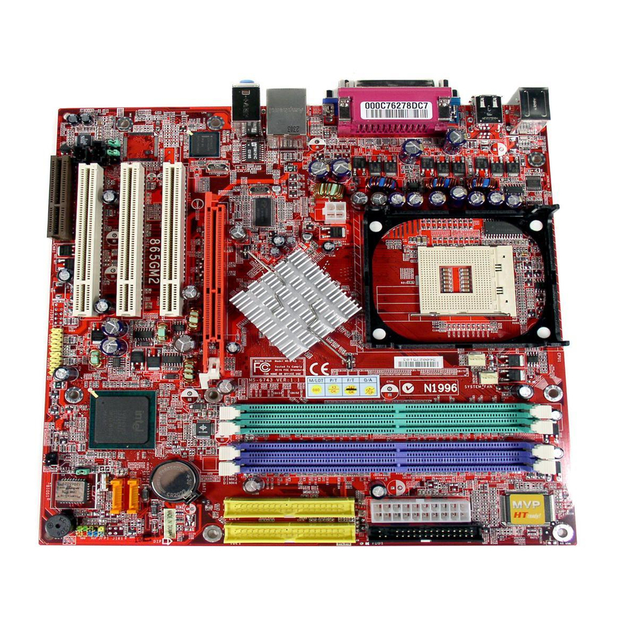
Page 11: Mainboard Layout
MS-6743 M-ATX Mainboard Mainboard Layout T: mouse B: keyboard SYSTEM_FAN CPU_FAN JPW1 Intel Springdale 865PE/G Line-In Line-Out B:Mic AG P Slot Intel 82562EZ PCI Slot 1 BATT PCI Slot 2 SATA2 D72874GC JIR1 ICH5 SATA1 JAUD1 PCI Slot 3 JCD1 JBAT1 Codec BIOS... -
Page 12: Msi Special Features
BIOS/drivers online so that you don’t need to search for the correct BIOS/driver version throughout the Web site. To use the function, you need to install the “MSI Live Update 2” application. After installation, the “MSI Live Update 2” icon (as shown on the right) will appear on the screen. -
Page 13: Live Monitor
Live Monitor™ The Live Monitor™ is a tool used to schedule the search for the latest BIOS/drivers version on the MSI Web site. To use the function, you need to install the “MSI Live Update 2” application. After installation, the “MSI Live Monitor” icon (as shown on the right) will appear on the screen. -
Page 14: Pc Alert™ 4
Getting Started PC Alert™ 4 The PC Alert 4 is a utility you can find in the CD-ROM disk. The utility is just like your PC doctor that can detect the following PC hardware status during real time operation: monitor CPU & system temperatures monitor fan speeds monitor system voltages If one of the items above is abnormal, the program main screen will be... - Page 15 CPU and chipset. Right-click the mouse to select the skin you want to switch to. Cute MSI Reminds You... 1. The new feature COOLER XP will work only if your mainboard supports AMD Athlon™ XP CPU.
-
Page 16: Chapter 2. Hardware Setup
Hardware Setup Chapter 2. Hardware Setup Hardware Setup This chapter tells you how to install the CPU, memory modules, and expansion cards, as well as how to setup the jump- ers on the mainboard. Also, it provides the instructions on con- necting the peripheral devices, such as the mouse, keyboard, etc. -
Page 17: Quick Components Guide
MS-6743 M-ATX Mainboard Quick Components Guide CPU_FAN1, p.2-18 SYSTEM_FAN1, p.2-18 JPW1, p.2-9 CPU, p.2-3 DDR DIMMs, p.2-7 ATX1, p.2-9 FDD1, p.2-16 Back Panel I/O, p.2-10 IDE1 AGP slot, p.2-29 IDE2, p.2-17 STAT2 PCI slots, p.2-29 SATA1, p.2-22 JIR1, p.2-20 JAUD1, p.2-24 JFP1, p.2-21 JCD1, p.2-19 JSPD1, p.2-19... -
Page 18: Central Processing Unit: Cpu
Hardware Setup Central Processing Unit: CPU The mainboard supports Intel Pentium 4/Celeron Northwood/Prescott ® ® processor in the 478 pin package. The mainboard uses a CPU socket called PGA478 for easy CPU installation. When you are installing the CPU, make sure the CPU has a heat sink and a cooling fan attached on the top to prevent overheating. -
Page 19: Cpu Installation Procedures For Socket 478
MS-6743 M-ATX Mainboard CPU Installation Procedures for Socket 478 Please turn off the power and Open Lever unplug the power cord before installing the CPU. Sliding 90 degree Plate Pull the lever sideways away from the socket. Make sure to raise the lever up to a 90- degree angle. -
Page 20: Installing The Cpu Fan
Hardware Setup Installing the CPU Fan As processor technology pushes to faster speeds and higher performance, thermal management becomes increasingly important. To dissipate heat, you need to attach the CPU cooling fan and heatsink on top of the CPU. Follow the instructions below to install the Heatsink/Fan: 1. - Page 21 5. Connect the fan power cable from the mounted fan to the 3-pin fan power connector on the board. fan power cable MSI Reminds You... Overheating Overheating will seriously damage the CPU and system, al- ways make sure the cooling fan can work properly to protect the CPU from overheating.
-
Page 22: Memory
Hardware Setup Memory The mainboard provides 2 slots for 184-pin DDR SDRAM DIMM (Double In-Line Memory Module) modules and supports the memory size up to 2GB. You can install DDR400/DDR333/DDR266 modules on the DDR DIMM slots (DDR 1~2). Introduction to DDR SDRAM DDR (Double Data Rate) SDRAM is similar to conventional SDRAM, but doubles the rate by transferring data twice per cycle. -
Page 23: Dimm Module Combination
3. The plastic clip at each side of the DIMM slot will automatically close. Notch Volt MSI Reminds You... You can barely see the golden finger if the module is properly inserted in the socket. -
Page 24: Power Supply
Hardware Setup Power Supply The mainboard supports ATX power supply for the power system. Be- fore inserting the power supply connector, always make sure that all compo- nents are installed properly to ensure that no damage will be caused. ATX 20-Pin Power Connector: ATX1 This connector allows you to connect to an ATX power supply. -
Page 25: Back Panel
MS-6743 M-ATX Mainboard Back Panel The back panel provides the following connectors: For Springdale-PE (Optional) Parallel (Optional) Mouse 1394 L-in COM A COM B Keyboard L-out For Springdale-G (Optional) Parallel (Optional) Mouse 1394 COM A L-in Keyboard L-out 2-10... -
Page 26: Mouse Connector
Hardware Setup Mouse Connector The mainboard provides a standard PS/2 ® mouse mini DIN connector for attaching a PS/2 mouse. You can plug a PS/2 mouse directly into this ® ® connector. The connector location and pin assignments are as follows: Pin Definition SIGNAL DESCRIPTION... -
Page 27: Lan Jack (Optional)
MS-6743 M-ATX Mainboard RJ-45 LAN Jack (Optional) The mainboard provides a RJ-45 connector that allows your computer to be connected to a network environment. Signal Description Activity Transmit differential pair Transmit differential pair Indicators Receive differential pair Not used Not used Receive differential pair Not used LAN Jack... -
Page 28: Vga Connector
Hardware Setup VGA Connector The mainboard provides a DB 15-pin female connector to connect a VGA monitor. Signal Description GREEN BLUE VGA Connector (DB 15-pin) Horizontal Sync Vertical Sync Audio Port Connectors Line Out is a connector for Speakers or Headphones. Line In is used for external CD player, Tape player, or other audio devices. -
Page 29: Ieee1394 Port (Optional)
MS-6743 M-ATX Mainboard IEEE1394 Port (Optional) The mainboard provides one standard IEEE1394 port. The standard IEEE1394 port connects to IEEE1394 devices without external power. The IEEE1394 high-speed serial bus complements USB by providing enhanced PC connectivity for a wide range of devices, including consumer electronics audio/video (A/V) appliances, storage peripherals, other PCs, and portable devices. -
Page 30: Parallel Port Connectors: Lpt1
Hardware Setup Parallel Port Connector: LPT1 The mainboard provides a 25-pin female centronic connector as LPT. A parallel port is a standard printer port that supports Enhanced Parallel Port (EPP) and Extended Capabilities Parallel Port (ECP) mode. Pin Definition SIGNAL DESCRIPTION STROBE Strobe... -
Page 31: Connectors
MS-6743 M-ATX Mainboard Connectors The mainboard provides connectors to connect to FDD, IDE HDD, case, modem, LAN, USB Ports, IR module and CPU/System/Power Supply FAN. Floppy Disk Drive Connector: FDD1 The mainboard provides a standard floppy disk drive connector that supports 360K, 720K, 1.2M, 1.44M and 2.88M floppy disk types. -
Page 32: Hard Disk Connectors: Ide1 & Ide2
IDE2 (Secondary IDE Connector) IDE2 can also connect a Master and a Slave drive. MSI Reminds You... If you install two hard disks on cable, you must configure the second drive to Slave mode by setting its jumper. Refer to the hard disk documentation supplied by hard disk vendors for jumper setting instructions. -
Page 33: Fan Power Connectors: Cpu_Fan/System_Fan
CPU fan control. SENSOR SYSTEM_FAN +12V +12V SENSOR CPU_FAN MSI Reminds You... Always consult the vendors for proper CPU cooling fan. 2-18... -
Page 34: Cd-In Connector: Jcd1
Hardware Setup CD-In Connector: JCD1 The connector is for CD-ROM audio connector. SPDIF-Out Connector: JSPD1 (Optional) This connector is used to connect SPDIF (Sony & Philips Digital Inter- connect Format) interface for digital audio transmission. JCD1 JSPD1 SPDIF Connected to JSPD1 SPDIF Bracket (Optional) 2-19... -
Page 35: Irda Infrared Module Header: Jir1 (865Pe Only)
MS-6743 M-ATX Mainboard IrDA Infrared Module Header: JIR1 (865PE only) The connector allows you to connect to IrDA Infrared module. You must configure the setting through the BIOS setup to use the IR function. JIR1 is compliant with Intel ® Front Panel I/O Connectivity Design Guide. -
Page 36: Front Panel Connector: Jfp1
Hardware Setup Front Panel Connector: JFP1 The mainboard provides two front panel connectors for electrical connection to the front panel switches and LEDs. JFP1 is compliant with Intel ® Front Panel I/O Connectivity Design Guide. JFP1 Power Reset Switch Switch Power JFP1 Pin Definition SIGNAL... -
Page 37: Serial Ata Connectors: Sata1/Sata2
MS-6743 M-ATX Mainboard Serial ATA Connectors: SATA1 / SATA2 The mainboard has dual high-speed Serial ATA interface connectors, SATA1 & SATA2. Each supports 1 generation serial ATA data rates of 150 MB/s. Both connectors are fully compliant with Serial ATA 1.0 specifications. Each Serial ATA connector can connect to 1 hard disk device. - Page 38 Optional Serial ATA cable connect to the hard disk devices Connect to SATA1 or SATA2 MSI Reminds You... Please do not fold the serial ATA cable in a 90-degree angle, which will cause the loss of data during the transmission. 2-23...
-
Page 39: Front Panel Audio Connector: Jaud1
Left channel audio signal to front panel AUD_RET_L Left channel audio signal return from front panel MSI Reminds You... If you don’t want to connect to the front audio header, pins 5 & 6, 9 & 10 have to be jumpered in order to have signal output directed to the rear audio ports. -
Page 40: Front Usb Connectors: Jusb1/Jusb2
Hardware Setup Front USB Connectors: JUSB1 / JUSB2 The mainboard provides one USB 2.0 pin header JUSB1 that is compli- ant with Intel I/O Connectivity Design Guide. USB 2.0 technology increases ® data transfer rate up to a maximum throughput of 480Mbps, which is 40 times faster than USB 1.1, and is ideal for connecting high-speed USB inter- face peripherals such as USB HDD, digital cameras, MP3 players, printers, modems and the like. -
Page 41: Ieee 1394 Connector: J1394_1
MS-6743 M-ATX Mainboard IEEE 1394 Connector: J1394_1 The mainboard provides three 1394 pin headers that allow you to con- nect optional IEEE 1394 ports. J1394_1 J1394_1 Pin Definition SIGNAL SIGNAL TPA+ TPA- Ground Ground TPB+ TPB- Cable power Cable power Key (no pin) Ground 2-26... - Page 42 Hardware Setup How to attach the IEEE 1394 Port: Connected separately to J1394_1, J1394_2 and J1394_3. 1394 Port Foolproof design 2-27...
-
Page 43: Jumpers
Keep Data Clear Data JBAT1 MSI Reminds You... You can clear CMOS by shorting 2-3 pin while the system is off. Then return to 1-2 pin position. Avoid clearing the CMOS while the system is on; it will damage the mainboard. -
Page 44: Slots
Hardware Setup Slots The motherboard provides one AGP slot and three 32-bit PCI bus slots. AGP Slot PCI Slots CNR Slot AGP (Accelerated Graphics Port) Slot The AGP slot allows you to insert the AGP graphics card. AGP is an interface specification designed for the throughput demands of 3D graphics. -
Page 45: Pci Interrupt Request Routing
MS-6743 M-ATX Mainboard PCI Interrupt Request Routing The IRQ, abbreviation of interrupt request line and pronounced I-R-Q, are hardware lines over which devices can send interrupt signals to the microprocessor. The PCI IRQ pins are typically connected to the PCI bus INT A# ~ INT D# pins as follows: Order 1 Order 2... -
Page 46: Chapter 3. Bios Setup
BIOS Setup Chapter 3. BIOS Setup BIOS Setup This chapter provides information on the BIOS Setup program and allows you to configure the system for optimum use. You may need to run the Setup program when: An error message appears on the screen during the system booting up, and requests you to run SETUP. -
Page 47: Entering Setup
MS-6743 M-ATX Mainboard Entering Setup Power on the computer and the system will start POST (Power On Self Test) process. When the message below appears on the screen, press <DEL> key to enter Setup. Press DEL to enter SETUP If the message disappears before you respond and you still wish to enter Setup, restart the system by turning it OFF and On or pressing the RESET button. -
Page 48: Getting Help
Press <Esc> to exit the Help screen. MSI Reminds You... The items under each BIOS category described in this chapter are under continuous update for better system performance. -
Page 49: The Main Menu
MS-6743 M-ATX Mainboard The Main Menu ® Once you enter Phoenix-Award BIOS CMOS Setup Utility, the Main Menu (Figure 1) will appear on the screen. The Main Menu allows you to select from twelve setup functions and two exit choices. Use arrow keys to select among the items and press <Enter>... - Page 50 BIOS Setup PC Health Status This entry shows your PC health status. Frequency/Voltage Control Use this menu to specify your settings for frequency/voltage control. Load High Performance Defaults Use this menu to load the BIOS values for the best system performance, but the system stability may be affected.
-
Page 51: Standard Cmos Features
MS-6743 M-ATX Mainboard Standard CMOS Features The items in Standard CMOS Features Menu are divided into 11 categories. Each category includes no, one or more than one setup items. Use the arrow keys to highlight the item and then use the <PgUp> or <PgDn> keys to select the value you want in each item. - Page 52 Landing Zone Cylinder location of the landing zone. Sector Number of sectors. MSI Reminds You... IDE Channel 2/3 Master only available when the following two conditions come into existence at the same time: BIOS version after 2.0 On-Chip Serial ATA is set to Auto (please refer Integrated Peripherals/OnChip IDE Device/On-Chip Serial ATA for details.)
- Page 53 MS-6743 M-ATX Mainboard Drive A:/B: This item allows you to set the type of floppy drives installed. Available options: None, 360K, 5.25 in., 1.2M, 5.25 in., 720K, 3.5 in., 1.44M, 3.5 in., 2.88M, 3.5 in.. Video The setting controls the type of video adapter used for the primary monitor of the system.
-
Page 54: Advanced Bios Features
BIOS Setup Advanced BIOS Features BIOS Virus Warning The item is to set the Virus Warning feature for IDE Hard Disk boot sector protection. If the function is enabled and any attempt to write data into this area is made, BIOS will display a warning message on screen and beep. Settings: Disabled and Enabled. - Page 55 MS-6743 M-ATX Mainboard MSI Reminds You... Enabling the functionality of Hyper-Threading Technology for your computer system requires ALL of the following platform Components: ® ® *CPU: An Intel Pentium 4 Processor with HT Technology; ® *Chipset: An Intel Chipset that supports HT Technology;...
- Page 56 BIOS Setup Boot Other Device Setting the option to Enabled allows the system to try to boot from other device if the system fails to boot from the 1st/2nd/3rd boot device. Swap Floppy Drive Setting to Enabled will swap floppy drives A: and B:. Boot Up NumLock LED This setting is to set the Num Lock status when the system is powered on.
- Page 57 MS-6743 M-ATX Mainboard Option Description Setup The password prompt appears only when end users try to run Setup. System A password prompt appears every time when the com- puter is powered on or when end users try to run Setup. APIC Function This field is used to enable or disable the APIC (Advanced Programmable Interrupt Controller).
-
Page 58: Advanced Chipset Features
BIOS Setup Advanced Chipset Features MSI Reminds You... Change these settings only if you are familiar with the chipset. DRAM Timing Selectable Selects whether DRAM timing is controlled by the SPD (Serial Presence Detect) EEPROM on the DRAM module. Setting to By SPD enables DRAM timings to be determined by BIOS based on the configurations on the SPD. - Page 59 MS-6743 M-ATX Mainboard or refreshed. Fast speed offers faster performance while slow speed offers more stable performance. Settings: 4, 3, 2 (clocks). DRAM RAS# Precharge This item controls the number of cycles for Row Address Strobe (RAS) to be allowed to precharge. If insufficient time is allowed for the RAS to accumulate its charge before DRAM refresh, refresh may be incomplete and DRAM may fail to retain data.
- Page 60 BIOS Setup AGP Aperture Size (MB) This setting controls just how much system RAM can be allocated to AGP for video purposes. The aperture is a portion of the PCI memory address range dedicated to graphics memory address space. Host cycles that hit the aperture range are forwarded to the AGP without any translation.
-
Page 61: Integrated Peripherals
MS-6743 M-ATX Mainboard Integrated Peripherals OnChip IDE Device Press <Enter> to enter the sub-menu and the following screen appears: IDE HDD Block Mode Block mode is also called block transfer, multiple commands, or multiple sector read/write. If your IDE hard drive supports block mode (most new drives do), select [Enabled] for automatic detection of the optimal number of block read/write per sector the drive can support. - Page 62 BIOS Setup IDE DMA Transfer Support This item is used to enable or disable the DMA transfer function of the IDE Hard Drive. The settings are: Enabled, Disabled. On-Chip Primary/Secondary PCI IDE The integrated peripherals controller contains an IDE interface with support for two IDE channels.
- Page 63 MS-6743 M-ATX Mainboard Serial ATA Port 0/1 Mode Select a compatible mode for Port 1 and Port 2 from Award setting to the chipset settings: 1. Primary Master Compatible Mode with Serial ATA Port 1 set to Primary Master. 2. Primary Slave Compatible Mode with Serial ATA Port 1 set to Primary Slave.
- Page 64 BIOS Setup USB Controller This setting is used to enable/disable the onboard USB controller. Set- ting options: Disabled, Enabled. USB 2.0 Controller Set to Enabled if you need to use any USB 2.0 device in the operating system that does not support or have any USB 2.0 driver installed, such as DOS and SCO Unix.
- Page 65 MS-6743 M-ATX Mainboard Onboard Super IO Device Press <Enter> to enter the sub-menu and the following screen appears: POWER ON Function This controls how the PS/2 mouse or keyboard can power on the system. Settings: Password, Hot KEY, Mouse Left, Mouse Left, Mouse Right, any KEY, BUTTON ONLY, Keyboard 98.
- Page 66 BIOS Setup Onboard Serial Port 1/Onboard Serial Port 2 (865PE only) Select an address and corresponding interrupt for the first and second serial ports. The settings are: 3F8/IRQ4, 2E8/IRQ3, 3E8/IRQ4, 2F8/IRQ3, Disabled, Auto. UART Mode Select This setting allows you to specify the operation mode for serial port 2. Setting options: IrDA, ASKIR, Normal.
- Page 67 MS-6743 M-ATX Mainboard Parallel Port Mode SPP : Standard Parallel Port EPP : Enhanced Parallel Port ECP : Extended Capability Port ECP + EPP: Extended Capability Port + Enhanced Parallel Port SPP/EPP/ECP/ECP+EPP To operate the onboard parallel port as Standard Parallel Port only, choose “SPP.”...
-
Page 68: Power Management Setup
BIOS Setup Power Management Setup MSI Reminds You... S3-related functions described in this section are available only when your BIOS supports S3 sleep mode. Sleep State This item specifies the power saving modes for ACPI function. Options are: S1/POS The S1 sleep mode is a low power state. In this state, no system context is lost (CPU or chipset) and hardware maintains all system context. - Page 69 MS-6743 M-ATX Mainboard Run VGABIOS if S3 Resume When ACPI Suspend Mode is set to S3 or S1&S3, users can select the options in this field. Selecting [Yes] allows BIOS to call VGABIOS to initializet he VGA card when system wakes up (resumes) from S3 sleep state. The system resume time is shortened when you disable the function, but system will need an AGP driver to initialize the VGA card.
- Page 70 These fields specify whether the system will be awakened from power saving modes when activity or input signal of the specified hardware peripheral or component is detected. Options: Enabled, Disabled. MSI Reminds You... You need to install a modem card supporting power on function for “Wake Up On Ring” function.
- Page 71 The field specifies the time for Resume By RTC Alarm. Format is <hour> <minute><second>. MSI Reminds You... If you have changed this setting, you must let the system boot up until it enters the operating system, before this function will work.
-
Page 72: Pnp/Pci Configurations
BIOS Setup PNP/PCI Configurations This section describes configuring the PCI bus system and PnP (Plug & Play) feature. PCI, or Peripheral Component Interconnect, is a system which al- lows I/O devices to operate at speeds nearing the speed the CPU itself uses when communicating with its special components. - Page 73 MS-6743 M-ATX Mainboard IRQ Resources The items are adjustable only when Resources Controlled By is set to Manual. Press <Enter> and you will enter the sub-menu of the items. IRQ Resources list IRQ 3/4/5/7/9/10/11/12/14/15 for users to set each IRQ a type depending on the type of device using the IRQ.
-
Page 74: Pc Health Status
BIOS Setup PC Health Status This section shows the status of your CPU, fan, overall system status, etc. Monitor function is available only if there is hardware monitoring mechanism onboard. Chassis Intrusion Detect The field enables or disables the feature of recording the chassis intrusion status and issuing a warning message if the chassis is once opened. - Page 75 MS-6743 M-ATX Mainboard CPU Smart Fan Temperature Select a temperature setting here, and if the temperature of the CPU climbs up to the selected temperature setting, the system will automatically in- crease the speed of the CPU fan to cool down the overheated CPU. Settings: 30¢...
-
Page 76: Frequency/Voltage Control
BIOS Setup Frequency/Voltage Control Use this menu to specify your settings for frequency/voltage control. Auto Detect PCI Clk This option allows you to enable/disable the feature of auto detecting the clock frequency of the installed PCI bus. The settings are: Enabled, Disabled. Spread Spectrum When the motherboard’s clock generator pulses, the extreme values (spikes) of the pulses creates EMI (Electromagnetic Interference). - Page 77 MS-6743 M-ATX Mainboard CPU Vcore Adjust This item specifies the voltage of CPU Vcore. Setting options: 1.425, 1.45, 1. 475,1.5, 1.525, 1.55, 1.575, 1.6, 1.625, 1.65, 1.675, 1.7, 1.725, 1.75, 1.775, and 1.8. AGP/PCI Clock Control This item is used to control the synchronous setting between CPU frequency and AGP/PCI clock.
-
Page 78: Load High Performance/Bios Setup Defaults
BIOS Setup Load High Performance/BIOS Setup Defaults The two options on the main menu allow users to restore all of the BIOS settings to the High Performance Defaults or BIOS Setup Defaults. The High Performance Defaults are the default values set by the mainboard manufac- turer specifically for optimal performance of the mainboard. -
Page 79: Set Supervisor/User Password
Security Option is set to System, the password is required both at boot and at entry to Setup. If set to Setup, password prompt only occurs when you try to enter Setup. MSI Reminds You... About Supervisor Password & User Password: Supervisor password: Can enter and change the settings of the setup menu. -
Page 80: Appendix: Using 2-, 4- Or 6-Channel Audio Function
Using 2-, 4- or 6-Channel Audio Function Appendix. Using 4- or 6-Channel Appendix: Using 2-, 4- or 6-Channel Audio Audio Function Function The motherboard comes with C-Media 9739A AC’97 audio chip, which pro- vides exclusive Xear 3D technology, a value-add PC audio total solution.In addtion, C-Media designs a Universal Driver Architecture (UDA driver) which has a flexible interface so that it can be applied to different platforms and all C- Media audio chips. -
Page 81: Installing C-Media Driver
MS-6743 M-ATX Mainboard Installing C-Media Drivers The mainboard is able to transform the audio connectors on the back panel from 2-channel to 4-/6-channel. To use the function, you need to install the C- Media UDA driver. The UDA driver supports all Windows, C-Midia AC’97 CODEC, and audio controllers (south bridges) on board. - Page 82 Using 2-, 4- or 6-Channel Audio Function 5. Sound Effects - Equalizer: It offers 10-band Equalizer and 12 pre-set models like “Live”, “Jazz” and so on for users to modify the frequency response of sound singals. There is also “User Defined” list for users to save their own settings.
-
Page 83: Hardware Configuration
MS-6743 M-ATX Mainboard Hardware Configuration After installing the audio driver, you are able to use the 4-/6-channel audio feature now. To enable 4- or 6-channel audio operation, first connect 4 or 6 speakers to the appropriate audio connectors, and then select 4- or 6-channel audio setting in the software utility. -
Page 84: Software Configuration
Using 2-, 4- or 6-Channel Audio Function Software Configuration To have 4-/6-channel audio work, you must set appropriate configuration in the C-Media software application. Click the C-Media Mixer icon from the window tray on the bottom, and choose Open. Then the “C-Media 3D Audio Configuration” will appear . Click on the Speaker Output tab to configure the audio. - Page 85 MS-6743 M-ATX Mainboard Center/Bass Output Swap: Enabling this option will exchange the center/ bass output channel. PC speaker manufactures define typically that the center signal is delivered by tip of the stereo plug and the bass signal is by ring of it, as the figure showed below. However, some speakers have opposite definition.
- Page 86 Using 2-, 4- or 6-Channel Audio Function S/PDIF Click on the S/PDIF tab and the following screen appears. Playing Audio (48 kHz Output): Playing Digital Audio to Digital S/ PDIF Output. Choosing this option allows the output digital playing audio from your computer like DVD, VCD, digital CD, MP3, Wave... etc through S/PDIF in 48KHz sample rate.
- Page 87 MS-6743 M-ATX Mainboard Choose the Analog Input to S/PDIF-Out and then click the Select Source button. Then the Select Source window appears. Select Source: Since the analog input signal needs to be recorded and converted to digital format, you have to click Select Source button and select one analog source in the “Select Source”...
- Page 88 Using 2-, 4- or 6-Channel Audio Function Volumn Control Click on the Volumn Control tab and the following screen appears. Reset all to default value (0dB) You may regulate each volumn to the speaker for current playing digital sound sources. If you use 2-channel speaker, only Front Left and Front Right bars are available for you to configure.
- Page 89 MS-6743 M-ATX Mainboard Microphone Click on the Microphone tab and the following screen appears. Mute Microphone: Check this item to disable microphone inputs. Microphone Selection: You may select the microphone input you are going to use. But if your system does not support 2 microphone inputs, then you won’t see two items.
- Page 90 Using 2-, 4- or 6-Channel Audio Function Xear 3D Click on the Xear 3D tab and the following screen appears. C-Media UDA driver now supports Xear 3D-5.1 Virtual SPEAKER SHIRFTER and sound effects. Just click the left button in Xear 3D tab and the new friendly/fancy graphic user interface will pop up as follows.
- Page 91 MS-6743 M-ATX Mainboard 1. Sound Effect From this part, you may choose the sound effect you like from 27 environ- ment effects, 3 environment sizes and 10-band pre-set equalizer. You may choose the provided environ- ments by clicking the buttons (Bathroom, Concert Hall, Sewer Pipe and Music Pub) Listening Envi-...
- Page 92 Using 2-, 4- or 6-Channel Audio Function 2. Demo Program This part contains multi-channel music (including speakers testing) demo program. 3 pieces of 5.1-chan- nel music for your selection. 5.1-channel speaker environmenmt. You may click each speaker to get one channel sound. If it has sound, it will be lighted up.
- Page 93 MS-6743 M-ATX Mainboard 3. Xear 3D-5.1 Virtual SPEAKER SHIFTER This part provides an advanced, amazing and considerate feature- dynamically adjustable multi-channel sound system no matter what listening appliance you are using and what application you are running. The default setting for SPEAKER SHIFTER is OFF, thus you have to click on it to make it ON, in which all the speakers are available to adjust.
- Page 94 One Touch Setup during the setup procedure when you insert the MSI software driver, you may only see the Sound Effect tab in the Xear 3D Advanced Program. Demo Program will not be installed automatically. Please click C-Media Sound Drivers again for the complete installation of C-Media applications.
- Page 95 MS-6743 M-ATX Mainboard The Xear3D Sound - Play3D Demo program is showed as follows: Five built-in Sound Sources. Five Moving Paths. Six Envornment Effects, which will synchronize with the Environment setting on “Sound Effect” part. A-16...
- Page 96 Using 2-, 4- or 6-Channel Audio Function In the Moving Path selection, you may adjust your virtual speakers before playing 3D audio applications like gaming. When clicking each of the Moving Path icons (Drag Path, Horizontal Circle, Vertical Circle, Z Path and Random Curve), a rea moving ball indicates the 3D source source position.
-
Page 97: Using 2-, 4- Or 6-Channel Audio Function
MS-6743 M-ATX Mainboard Using 2-, 4- or 6-Channel Audio Function Attaching Speakers To perform multichannel audio operation, connect multiple speakers to the system. You should connect the same number of speakers as the audio chan- nels you will select in the software utility. Using Back Panel connectors: In addition to a default 2-Channel analog audio output function, the audio connectors on the Back Panel also provide 4- or 6-Channel analog audio out-... - Page 98 Using 2-, 4- or 6-Channel Audio Function 4-Channel Analog Audio Output The audio jacks on the back panel always provide 2-channel analog audio output function, however these audio jacks can be transformed to 4- or 6- channel analog audio jacks by selecting the corresponding multi-channel op- eration from No.
- Page 99 MS-6743 M-ATX Mainboard 6-Channel Analog Audio Output Refer to the following diagram and caption for the founction of each jack on the back panel when 6-Channel Mode is selected. Line Out (Center and Subwoofer channel) Line Out (Rear channels) Line Out (Front channels) Back Panel * Both Line In and MIC function are converted to Line Out function when 4- Channel Mode for 6-Speaker Output is selected.
-
Page 100: Troubleshooting
Q: How do I know what MSI D-LED or D-bracket light mean? A: Please follow the special tech issue, http://www.msi.com.tw/support/ techexpress/special_tech/smartled.htm Q: I have got MSI Motherboard and when it says detecting drives, it detects them but says an error saying "Primary IDE Channel no 80 Conductor Cable Installed"... - Page 101 2. Try to clear the CMOS. If problem still persists, ask your reseller for new BIOS chip or contact one of MSI office near your place for new BIOS chip (http:/ /www.msi.com.tw/contact/main.htm). Q: Should I update my BIOS, once a new BIOS is released? A: A new BIOS is usually released due to the following reasons: 1.
- Page 102 BIOS, unless you really have to. Q: How do I update the BIOS? A: Please refer to http://www.msi.com.tw/support/bios/note.htm for details. Q: How do I identify the BIOS version? A: Upon boot-up, the 1st line appearing after the memory count is the BIOS version.
- Page 103 MS-6743 M-ATX Mainboard Q: After flashing the bios and rebooting the system, the screen went blank. A: For AMI BIOS Rename the desired AMI BIOS file to AMIBOOT.ROM and save it on a floppy disk. e.g. Rename A569MS23.ROM to AMIBOOT.ROM Insert this floppy disk in the floppy drive.
-
Page 104: Glossary
Glossary Glossary Glossary ACPI (Advanced Configuration & Power Interface) This power management specification enables the OS (operating system) to control the amount of power given to each device attached to the computer. Windows 98/98SE, Windows 2000 and Windows ME can fully support ACPI to allow users managing the system power flexibly. - Page 105 MS-6743 M-ATX Mainboard contents of frequently accessed RAM locations and the addresses where these data items are stored. Chipset A collection of integrated chips designed to perform one or more related functions. For example, a modem chipset contains all the primary circuits for transmitting and receiv- ing data;...
- Page 106 Glossary ECC Memory (Error Correcting Code Memory) A type of memory that contains special circuitry for testing the accuracy of data and correcting the errors on the fly. EEPROM Acronym for Electrically Erasable Programmable Read-Only Memory. An EEPROM is a special type of PROM that can be erased by exposing it to an electrical charge. Like other types of PROM, EEPROM retains its contents even when the power is turned off.
- Page 107 MS-6743 M-ATX Mainboard IDE (Integrated Drive Electronics) A type of disk-drive interface widely used to connect hard disks, CD-ROMs and tape drives to a PC, in which the controller electronics is integrated into the drive itself, eliminating the need for a separate adapter card. The IDE interface is known as the ATA (AT Attachment) specification.
- Page 108 Glossary LBA (Logical Block Addressing) Logical block addressing is a technique that allows a computer to address a hard disk larger than 528 megabytes. A logical block address is a 28-bit value that maps to a specific cylinder-head-sector address on the disk. 28 bits allows sufficient variation to specify addresses on a hard disk up to 8.4 gigabytes in data storage capacity.
- Page 109 MS-6743 M-ATX Mainboard PS/2 Port A type of port developed by IBM for connecting a mouse or keyboard to a PC. The PS/2 port supports a mini DIN plug containing just 6 pins. Most modern PCs equipped with PS/2 ports so that the special port can be used by another device, such as a modem.