
Related Manuals for MSI 845EV


Summary of Contents for MSI 845EV
- Page 1 845EV MICRO-STAR INTERNATIONAL MS-6566 (v1.X) ATX Mainboard Version 1.1 G52-M6566X2-K01...
- Page 2 Manual Rev: 1.1 Release Date: March 2003 FCC-B Radio Frequency Interference Statement This equipment has been tested and found to comply with the limits for a class B digital device, pursuant to part 15 of the FCC rules. These limits are designed to provide reasonable protection against harmful interference when the equip- ment is operated in a commercial environment.
- Page 3 Novell, Inc. ® Award is a registered trademark of Phoenix Technologies Ltd. ® is a registered trademark of American Megatrends Inc. ® Revision History Revision Revision History Date V1.1 Update specification, March 2003 MSI Special Features and BIOS...
- Page 4 Safety Instructions Read the safety instructions carefully. Save this User’s Guide for possible use later. Keep this equipment away from humidity. Lay this equipment on a stable and flat surface before setting it up. The openings on the enclosure are used for air convection and to prevent the equipment from overheating.
-
Page 5: Table Of Contents
Chapter 1. Getting Started ................ 1-1 Mainboard Specification ..............1-2 Mainboard Layout ................1-4 Quick Components Guide ..............1-5 MSI Special Features ................1-6 Fuzzy Logic™ 4 ................1-6 Live BIOS™/Live Driver™ ............1-7 D-Bracket™ (Optional) ..............1-8 PC Alert™ 4 ................. 1-10 Chapter 2. - Page 6 Audio Port Connectors ............... 2-10 Parallel Port Connector: LPT1 ............2-11 Connectors ..................2-12 Floppy Disk Drive Connector: FDD1 ........... 2-12 IrDA Infrared Module Header: JIR1 ..........2-12 Hard Disk Connectors: IDE1 & IDE2 ........... 2-13 CD-In Connector: JCD1 ............... 2-14 Aux Line-In Connector: JAUX1 ..........
- Page 7 The Main Menu ................... 3-4 Standard CMOS Features ..............3-6 Advanced BIOS Features ..............3-8 Advanced Chipset Features ............... 3-12 Power Management Setup ..............3-14 PNP/PCI Configurations ..............3-17 Integrated Peripherals ................ 3-19 Hardware Monitor Setup ..............3-22 Load High Performance/BIOS Setup Defaults ........3-24 Supervisor/User Password ..............
-
Page 8: Chapter 1. Getting Started
® Designed to fit the advanced Intel Pentium 4/Celeron processors in the 478 ® ® pin package, the MS-6566 delivers a high performance and professional desk- top platform solution. TOPICS Mainboard Specification Mainboard Layout Quick Components Guide MSI Special Features... -
Page 9: Mainboard Specification
Chapter 1 Mainboard Specification Support Intel Pentium 4/Celeron processor in 478 pin package ® ® Support 1.4GHz~3.06GHz processor - FSB 400MHz up to 1.4~2.6GHz - FSB 533MHz up to 2.26~3.06GHz Chipset Intel 845E chipset ® - AGP 4x slot (1.5V only) - Support 400/533MHz FSB - Support 400/533MHz Intel NetBurst micro-architecture bus Intel... - Page 10 Getting Started On-Board Peripherals On-board Peripherals include: - 1 floppy port supports 2 FDD with 360K, 720K, 1.2M, 1.44M and 2.88Mbytes - 2 serial ports (COM 1 + COM 2) - 1 parallel port supports SPP/EPP/ECP mode - 4 USB ports (Rear x 2/ Front x 2) - 1 Line-In/Line-Out/Mic-In/Game port Audio ICH2 chip integrated...
-
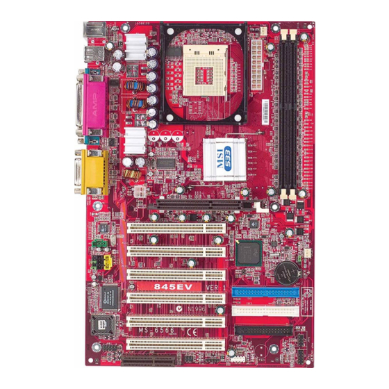
Page 11: Mainboard Layout
PCI Slot 1 Codec SFAN1 PCI Slot 2 JMD1 ICH 2 JBAT1 PCI Slot 3 BATT JGS1 PCI Slot 4 IDE 1 IDE 2 PCI Slot 5 PCI Slot 6 JFP2 FDD1 JDB1 JUSB1 JIR1 JFP1 JWR1 845EV (MS-6566 v1.X) ATX Mainboard... -
Page 12: Quick Components Guide
Getting Started Quick Components Guide Component Function Reference ATX 20-pin power connector See p. 2-7 JPW1 ATX 12V power connector See p. 2-7 JKBMS1 Mouse connector See p. 2-8 JKBMS1 Keyboard connector See p. 2-9 USB Connectors Connecting to USB devices See p. -
Page 13: Msi Special Features
After rebooting, click Turbo to apply the test result. Click Default to restore the default values. Features: MSI Logo links to the MSI Web site CPU Speed allows users to adjust the CPU speed through CPU Multiplier and FSB... -
Page 14: Live Bios™/Live Driver
BIOS/drivers online so that you don’t need to search for the correct BIOS/driver version throughout the Web site. To use the function, you need to install the “MSI Live Update 2” application. After the installation, the “MSI Live Update 2” icon (as shown on the right) will appear on the screen. -
Page 15: D-Bracket™ (Optional)
Chapter 1 D-Bracket™ (Optional) D-Bracket™ is a USB bracket integrating four Diagnostic LEDs, which use graphic signal display to help users understand their system. The LEDs provide up to 16 combinations of signals to debug the system. The 4 LEDs can debug all problems that fail the system, such as VGA, RAM or other failures. - Page 16 Getting Started Description D-Bracket Processor Initialization - This will show information regarding the processor (like brand name, system bus, etc...) Testing RTC (Real Time Clock) Initializing Video Interface - This will start detecting CPU clock, checking type of video onboard. Then, detect and initialize the video adapter.
-
Page 17: Pc Alert™ 4
Chapter 1 PC Alert™ 4 The PC Alert 4 is a utility you can find in the CD-ROM disk. The utility is just like your PC doctor that can detect the following PC hardware status during real time operation: monitor CPU & system temperatures monitor fan speeds monitor system voltages If one of the items above is abnormal, the program main screen will be... - Page 18 CPU and chipset. Right-click the mouse to select the skin you want to switch to. C u t e MSI Reminds You... The new feature COOLER XP will work only if your mainboard supports AMD Athlon XP CPU.
-
Page 19: Chapter 2. Hardware Setup
Hardware Setup Chapter 2. Hardware Setup Hardware Setup This chapter provides you with the information about hardware setup procedures. While doing the installation, be careful in holding the components and follow the installation procedures. For some components, if you install in the wrong orientation, the components will not work properly. -
Page 20: Central Processing Unit: Cpu
Chapter 2 Central Processing Unit: CPU ® ® The mainboard supports Intel Pentium 4 processor in the 478 pin package. The mainboard uses a CPU socket called PGA478 for easy CPU installation. When you are installing the CPU, make sure the CPU has a heat sink and a cooling fan attached on the top to prevent overheating. -
Page 21: Installing The Cpu Fan
Hardware Setup Installing the CPU Fan As processor technology pushes to faster speeds and higher performance, thermal management becomes increasingly important. To dissi- pate heat, you need to attach the CPU cooling fan and heatsink on top of the CPU. Follow the instructions below to install the Heatsink/Fan: 1. -
Page 22: Cpu Core Speed Derivation Procedure
Chapter 2 5. Connect the fan power cable from the mounted fan to the 3-pin fan power connector on the board. fan power cable CPU Core Speed Derivation Procedure CPU Clock 100MHz Core/Bus ratio then CPU core speed Host Clock x Core/Bus ratio 100MHz x 24 2.4GHz Overclocking... -
Page 23: Memory
Hardware Setup Memory The mainboard provides 2 slots for 184-pin, 2.5V unbuffered DDR DIMM with 4 memory banks. You can install PC1600/PC2100 DDR SDRAM modules on the DDR DIMM slots (DDR 1~2). To operate properly, at least one DIMM module must be installed. DDR DIMM Slots (DDR 1~2) Introduction to DDR SDRAM... -
Page 24: Ddr Module Combination
Chapter 2 DDR Module Combination You can install either single-sided or double-sided 184-pin DDR DIMM modules into DDR DIMM slots to meet your needs. Different from the SDR DIMM, the DDR DIMM has only one notch on the center of module. The number of pins on either side of the breaks are different. -
Page 25: Power Supply
Hardware Setup Power Supply The mainboard supports ATX power supply for the power system. Be- fore inserting the power supply connector, always make sure that all compo- nents are installed properly to ensure that no damage will be caused. ATX 20-Pin Power Connector: JW1 This connector allows you to connect to an ATX power supply. -
Page 26: Back Panel
Chapter 2 Back Panel The Back Panel provides the following connectors: Parallel Mouse Midi/Joystick L-out L-in MIC Keyboard COM A COM B Mouse Connector: JKBMS1 ® The mainboard provides a standard PS/2 mouse mini DIN connector for ® ® attaching a PS/2 mouse. -
Page 27: Keyboard Connector: Jkbms1
Hardware Setup Keyboard Connector: JKBMS1 ® The mainboard provides a standard PS/2 keyboard mini DIN connector ® ® for attaching a PS/2 keyboard. You can plug a PS/2 keyboard directly into this connector. Pin Definition SIGNAL DESCRIPTION Keyboard DATA Keyboard DATA No connection Ground Keyboard Clock... -
Page 28: Serial Port Connector: Com A & Com B
Chapter 2 Serial Port Connector: COM A & COM B The mainboard offers two 9-pin male DIN connectors as serial ports COM A and COM B. The ports are 16550A high speed communication ports that send/receive 16 bytes FIFOs. You can attach a serial mouse or other serial devices directly to them. -
Page 29: Parallel Port Connector: Lpt1
Hardware Setup Parallel Port Connector: LPT1 The mainboard provides a 25-pin female centronic connector for LPT. A parallel port is a standard printer port that supports Enhanced Parallel Port (EPP) and Extended Capabilities Parallel Port (ECP) mode. Pin Definition SIGNAL DESCRIPTION STROBE Strobe... -
Page 30: Connectors
Chapter 2 Connectors The mainboard provides connectors to connect to FDD, IDE HDD, case, modem, LAN, USB Ports, IR module and CPU/System FAN. Floppy Disk Drive Connector: FDD1 The mainboard provides a standard floppy disk drive connector that supports 360K, 720K, 1.2M, 1.44M and 2.88M floppy disk types. FDD1 IrDA Infrared Module Header: JIR1 This connector allows you to connect to IrDA Infrared modules. -
Page 31: Hard Disk Connectors: Ide1 & Ide2
Hardware Setup Hard Disk Connectors: IDE1 & IDE2 The mainboard has a 32-bit Enhanced PCI IDE and Ultra DMA 33/66/100 controller that provides PIO mode 0~4, Bus Master, and Ultra DMA/33/66/100 function. You can connect up to four hard disk drives, CD-ROM, 120MB Floppy (reserved for future BIOS) and other devices. -
Page 32: Cd-In Connector: Jcd1
Chapter 2 CD-In Connector: JCD1 The connector is for CD-ROM audio connector. Aux Line-In Connector: JAUX1 The connector is for DVD add-on card with Line-in connector. Modem-In Connector: JMD1 The connector is for modem with internal audio connector. JMD1 Mono_Out Phone_In JCD1 JAUX1... -
Page 33: Fan Power Connectors: Cfan1/Sfan1
Hardware Setup Fan Power Connectors: CFAN1/SFAN1 The CFAN1 (processor fan) and SFAN1 (system fan) support system cooling fan with +12V. It supports three-pin head connector. When connect- ing the wire to the connectors, always take note that the red wire is the positive and should be connected to the +12V, the black wire is Ground and should be connected to GND. -
Page 34: Wake On Ring Connector: Jwr1
Chapter 2 Wake On Ring Connector: JWR1 This connector allows you to connect to a modem card with Wake On Ring function. The connector will power up the system when a signal is re- ceived through the modem card. Signal MDM_WAKEUP 5VSB JWR1... -
Page 35: Front Panel Connector: Jfp1 & Jfp2
Hardware Setup Front Panel Connector: JFP1 & JFP2 The mainboard provides two front panel connectors for establishing electrical connection to the front panel switches and LEDs. Users can choose ® either JFP1 or JFP2. Both JFP1 and JFP2 are compliant with Intel Front Panel I/O Connectivity Design Guide. -
Page 36: Front Panel Audio Connector: Jaud1
Chapter 2 Front Panel Audio Connector: JAUD1 You can connect an optional audio connector to the JAUD1 front panel ® audio connector. The JAUD1 is compliant to Intel Front Panel I/O Connectiv- ity Design Guide. JAUD1 Pin Definition SIGNAL DESCRIPTION AUD_MIC Front panel microphone input signal AUD_GND... -
Page 37: Front Usb Connectors: Jusb1
Hardware Setup Front USB Connector: JUSB1 The mainboard provides a front Universal Serial Bus connector for you ® to connect to USB devices. The JUSB1 connector is compliant with Intel Front Panel I/O Connectivity Design Guide. JUSB1 JUSB1 Pin Definition Description Description USBPWR... -
Page 38: D-Bracket™ Connector: Jdb1
Chapter 2 D-Bracket™ Connector: JDB1 The mainboard comes with a JDB1 connector for you to connect to D- Bracket™. D-Bracket™ is a USB Bracket integrating four LEDs and allows users to identify system problem through 16 various combinations of LED signals. -
Page 39: Jumpers
Hardware Setup Jumpers The motherboard provides one jumper for you to set the computer’s function. This section will explain how to change your motherboard’s function through the use of the jumper. Clear CMOS Jumper: JBAT1 There is a CMOS RAM on board that has a power supply from external battery to keep the data of system configuration. -
Page 40: Slots
3V AGP card may cause damages to the mainboard. To avoid the risk of causing permanent damages to the mainboard, the AGP slot is protected with MSI electrical routing device. If users have inserted a 3.3V AGP card into the slot, the MSI routing device will disable the computer’s boot-up system. Re- move the 3.3V AGP card and the boot-up system will return to normal. -
Page 41: Pci Slots
Hardware Setup Attention! DO NOT use the following AGP cards which would result in failure to restart the system. The following list is subject to change without prior notice. Model AGP Chip ATI Xpert2000 3D RAGE 128VR ATI Rage Furry Maxx 3D RAGE 128 Pro Diamond Monster Fusion 3DFX VooDoo Banshee... -
Page 42: Pci Interrupt Request Routing
Chapter 2 PCI Interrupt Request Routing The IRQ, abbreviation of interrupt request line and pronounced I-R-Q, are hardware lines over which devices can send interrupt signals to the microprocessor. The PCI IRQ pins are typically connected to the PCI bus INT A# ~ INT D# pins as follows: Order 1 Order 2... - Page 43 AMI BIOS Setup Chapter 3. BIOS Setup AMI BIOS Setup This chapter provides information on the BIOS Setup program and allows you to configure the system for optimum use. You may need to run the Setup program when: An error message appears on the screen during the system booting up, and requests you to run SETUP.
-
Page 44: Entering Setup
Chapter 3 Entering Setup Power on the computer and the system will start POST (Power On Self Test) process. When the message below appears on the screen, press <DEL> key to enter Setup. DEL:Setup F11:Boot Menu F12:Network boot TAB:Logo If the message disappears before you respond and you still wish to enter Setup, restart the system by turning it OFF and On or pressing the RESET button. -
Page 45: Control Keys
AMI BIOS Setup Control Keys <↑> Move to the previous item <↓> Move to the next item Move to the item in the left hand <←> <→> Move to the item in the right hand <Enter> Select the item <Esc> Jumps to the Exit menu or returns to the main menu from a submenu <+/PU>... -
Page 46: The Main Menu
Chapter 3 The Main Menu Once you enter AMIBIOS SIMPLE SETUP UTILITY, the Main Menu will ap- pear on the screen. The Main Menu displays twelve configurable functions and two exit choices. Use arrow keys to move among the items and press <Enter>... - Page 47 AMI BIOS Setup Integrated Peripherals Use this menu to specify your settings for integrated peripherals. Hardware Monitor Setup This entry shows your PC’s current status, and allows you to adjust CPU clock, core voltage, ratio and DDR voltage. Load High Performance Defaults Use this menu to load the BIOS values for the best system performance, but the system stability may be affected.
-
Page 48: Standard Cmos Features
Chapter 3 Standard CMOS Features The items inside STANDARD CMOS SETUP menu are divided into 9 catego- ries. Each category includes none, one or more setup items. Use the arrow keys to highlight the item you want to modify and use the <PgUp> or <PgDn> keys to switch to the value you prefer. - Page 49 AMI BIOS Setup Pri Master/Pri Slave/Sec Master/Sec Slave Press PgUp/<+> or PgDn/<-> to select the hard disk drive type. The specifica- tion of hard disk drive will show up on the right hand according to your selection. TYPE Type of the device. SIZE Capacity of the device.
-
Page 50: Advanced Bios Features
Chapter 3 Advanced BIOS Features Quick Boot Setting the item to Enabled allows the system to boot within 5 seconds since it will skip some check items. Available options: Enabled and Disabled. Full Screen Logo Show This item enables you to show the company logo on the bootup screen. Set- tings are: Disabled Shows the POST messages at boot. - Page 51 AMI BIOS Setup as LS-120 or ZIP drive, that functions as a floppy drive. ARMD-HDD The system will boot from ARMD device, such as MO or ZIP drive, that functions as hard disk drive. CDROM The system will boot from the CD-ROM. SCSI The system will boot from the SCSI.
- Page 52 Chapter 3 Swap Floppy Setting to Enabled will swap floppy drives A: and B:. Seek Floppy This setting causes the BIOS to search for floppy disk drives at boot time. When enabled, the BIOS will activate the floppy disk drives during the boot process: the drive activity light will come on and the head will move back and forth once.
- Page 53 AMI BIOS Setup L1 Cache Cache memory is additional memory that is much faster than conventional DRAM (system memory). When the CPU requests data, the system transfers the requested data from the main DRAM into cache memory, for even faster access by the CPU.
-
Page 54: Advanced Chipset Features
Chapter 3 Advanced Chipset Features Note: Change these settings only if you are familiar with the chipset. DRAM Frequency This item is used to configure the clock frequency of the installed DRAM. Settings: Auto, 200MHz, 266MHz. Configure DRAM Timing by This setting determines whether DRAM timing is controlled by the SPD (Serial Presence Detect) EEPROM on the DRAM module. - Page 55 AMI BIOS Setup be allowed to precharge. If insufficient time is allowed for the RAS to accumu- late its charge before DRAM refresh, refresh may be incomplete and DRAM may fail to retain data. This item applies only when synchronous DRAM is installed in the system.
-
Page 56: Power Management Setup
Chapter 3 Power Management Setup IPCA Function This item is to activate the ACPI (Advanced Configuration and Power Man- agement Interface) function. If your operating system is ACPI-aware, such as Windows 98SE/2000/ME, select Yes. Available options: Yes and No. ACPI Standby State This item specifies the power saving modes for ACPI function. - Page 57 AMI BIOS Setup (Suspend to RAM) sleep state. Settings: Enabled and Disabled. Mouse Wakeup From S3 This item allows the activity of the mouse to wake up the system from S3 (Suspend to RAM) sleep state. Settings: Enabled and Disabled. Keyboard Wakeup From S3 This item allows the activity of the keyboard to wake up the system from S3 (Suspend to RAM) sleep state.
- Page 58 Chapter 3 Wake Up On Ring When setting to Enabled, the feature allows your system to be awakened from the power saving modes through an incoming call from the modem. Settings: Enabled and Disabled. Note: You need to install a modem supporting power on function for Wake Up On Ring function.
-
Page 59: Pnp/Pci Configurations
AMI BIOS Setup PNP/PCI Configurations This section describes configuring the PCI bus system and PnP (Plug & Play) feature. PCI, or Personal Computer Interconnect, is a system which allows I/O devices to operate at speeds nearing the speed the CPU itself uses when communicating with its special components. - Page 60 Chapter 3 VGA Palette Snoop Bit Setting Action Disabled Data read or written by the CPU is only directed to the PCI VGA device’s palette registers. Enabled Data read or written by the CPU is directed to both the PCI VGA device’s palette registers and the ISA VGA device’s palette registers, permitting the palette registers of both VGA devices to be identical.
-
Page 61: Integrated Peripherals
AMI BIOS Setup Integrated Peripherals USB Controller This setting is used to enable/disable the onboard USB controllers. Settings: All USB Port, Disabled, USB Port 0&1, USB Port 2&3. USB Legacy Support Set to All Device if your need to use any USB device in the operating system that does not support or have any USB driver installed, such as DOS and SCO Unix. - Page 62 Chapter 3 used, the onboard MC’97 (Modem Codec’97) controller will be enabled; if not, it is disabled. Disable the controller if you want to use other controller cards to connect to a modem. Settings: Auto, Disabled. Floppy Controller This is used to enable or disable the onboard Floppy controller. Option Description Auto...
- Page 63 AMI BIOS Setup O port address. Settings: Auto, 378, 278, 3BC and Disabled. Parallel Port Mode This item selects the operation mode for the onboard parallel port: ECP, Normal, Bi-Dir or EPP. EPP Version The item selects the EPP version used by the parallel port if the port is set to EPP mode.
-
Page 64: Hardware Monitor Setup
Chapter 3 Hardware Monitor Setup This section describes how to set the CPU FSB frequency, monitor the current hardware status including CPU/system temperatures, CPU/System Fan speeds, Vcore etc. Monitor function is available only if there is hardware monitoring mechanism onboard. CPU Ratio Selection This setting controls the multiplier that is used to determine the internal clock speed of the processor relative to the external or motherboard clock speed. - Page 65 AMI BIOS Setup performance. But if you are plagued by EMI, setting to Enabled for EMI reduction. Remember to disable Spread Spectrum if you are overclocking be- cause even a slight jitter can introduce a temporary boost in clockspeed which may just cause your overclocked processor to lock up.
-
Page 66: Load High Performance/Bios Setup Defaults
Chapter 3 Load High Performance/BIOS Setup Defaults The two options on the main menu allow users to restore all of the BIOS settings to High Performance defaults or BIOS Setup defaults. The High Per- formance Defaults are the default values set by the mainboard manufacturer for the best system performance but probably will cause a stability issue. -
Page 67: Supervisor/User Password
AMI BIOS Setup Supervisor/User Password When you select Supervisor Password, a message as below will appear on the screen: When you select User Password, a message as below will appear on the screen: Type the password, up to six characters in length, and press <Enter>. The password typed now will replace any previously set password from CMOS memory. - Page 68 Chapter 3 thorized use of your computer. The setting to determine when the password prompt is required is the PASSWORD CHECK option of the ADVANCED BIOS FEATURES menu. If the PASSWORD CHECK option is set to Always, the password is required both at boot and at entry to Setup. If set to Setup, pass- word prompt only occurs when you try to enter Setup.
-
Page 69: Ide Hdd Auto Detection
AMI BIOS Setup IDE HDD AUTO Detection You can use this utility to AUTOMATICALLY detect the characteristics of most hard drives. 3-27... -
Page 70: Glossary
Glossary Glossary Glossary ACPI (Advanced Configuration & Power Interface) This power management specification enables the OS (operating system) to control the amount of power given to each device attached to the computer. Windows 98/98SE, Windows 2000 and Windows ME can fully support ACPI to allow users managing the system power flexibly. - Page 71 Glossary example, a modem chipset contains all the primary circuits for transmitting and receiv- ing data; a PC chipset provides the electronic interfaces between all subsystems. CMOS (complementary metal-oxide semiconductor) CMOS is a widely used type of semiconductor, which features high speed and low power consumption.
- Page 72 Glossary ECC Memory (error correcting code memory) A type of memory that contains special circuitry for testing the accuracy of data and correcting the errors on the fly. IDE (Integrated Drive Electronics) A type of disk-drive interface widely used to connect hard disks, CD-ROMs and tape drives to a PC, in which the controller electronics is integrated into the drive itself, eliminating the need for a separate adapter card.
- Page 73 Glossary PCI (Peripheral Component Interconnect) A local bus standard developed by Intel that first appeared on PCs in late 1993. PCI provides “plug and play” capability and allows IRQs to be shared. The PCI controller can exchange data with the system's CPU either 32 bits or 64 bits at a time. PnP (Plug and Play) A set of specifications that allows a PC to configure itself automatically to work with peripherals.