Table of Contents
Advertisement
Advertisement
Table of Contents

Related Manuals for MSI 865PE/G Neo2-P MS-6728


Summary of Contents for MSI 865PE/G Neo2-P MS-6728
- Page 1 865PE/G Neo2-P MS-6728 (v2.X) ATX Mainboard Version 2.0 G52-M6728XG...
-
Page 2: Fcc-B Radio Frequency Interference Statement
Manual Rev: 2.0 Release Date: September 2003 FCC-B Radio Frequency Interference Statement This equipment has been tested and found to comply with the limits for a class B digital device, pursuant to part 15 of the FCC rules. These limits are designed to provide reasonable protection against harmful interference when the equip- ment is operated in a commercial environment. -
Page 3: Copyright Notice
Copyright Notice The material in this document is the intellectual property of MICRO-STAR INTERNATIONAL. We take every care in the preparation of this document, but no guarantee is given as to the correctness of its contents. Our products are under continual improvement and we reserve the right to make changes without notice. -
Page 4: Safety Instructions
Safety Instructions Always read the safety instructions carefully. Keep this User’s Manual for future reference. Keep this equipment away from humidity. Lay this equipment on a reliable flat surface before setting it up. The openings on the enclosure are for air convection hence protects the equipment from overheating. -
Page 5: Table Of Contents
Revision History ................... iii Safety Instructions ..................iv Chapter 1. Getting Started ................ 1-1 Mainboard Specifications ..............1-2 Mainboard Layout ................1-4 MSI Special Features ................1-5 Super Pack (Optional) ..............1-5 CoreCenter ..................1-6 CoreCell™ ..................1-8 Color Management ................ 1-9 D-Bracket™... - Page 6 ATX 12V Power Connector: JPW1 ..........2-9 Back Panel ..................2-10 Mouse Connector ............... 2-11 Keyboard Connector ..............2-12 USB Connectors ................2-12 Serial Port Connectors: COM A ..........2-13 VGA Connector (For 865G only) ..........2-13 RJ-45 LAN Jack: 10/100 LAN (8100C) / Giga-bit LAN (8110S) (Optional) ........
- Page 7 PCI Interrupt Request Routing ............ 2-27 AGP (Accelerated Graphics Port) Slot ......... 2-27 PCI (Peripheral Component Interconnect) Slots ......2-27 Chapter 3. BIOS Setup ................3-1 Entering Setup ..................3-2 Selecting the First Boot Device ............. 3-2 Control Keys .................. 3-3 Getting Help ..................
- Page 8 For 865G Neo2-P and 865PE Neo2-P Option 1: ......A-13 For 865PE Neo2-P Option 2: ............A-16 Appendix B. Intel ICH5R Serial ATA RAID Introduction ......B-1 Introduction ..................B-2 BIOS Configuration ................B-5 Installing Software ................B-13 RAID Migration Instructions ............B-19 AppendixC.
-
Page 9: Chapter 1. Getting Started
Getting Started Chapter 1. Getting Started Getting Started Thank you for choosing the 865PE/G Neo2-P (MS-6728) ® v2.X ATX mainboard. The 865PE/G Neo2-P is based on Intel 865PE / 865G & ICH5 / ICH5R chipsets for optimal system ® ® efficiency. -
Page 10: Mainboard Specifications
MS-6728 ATX Mainboard Mainboard Specifications ® Supports Intel P4 Northwood/Prescott (Socket 478) processors. FSB 400 (for Northwood only), 533, 800MHz. Supports up to 3.2GHz or higher speed. Chipset ® Intel 865PE/G chipset - Supports FSB 800/533/400MHz. - Supports AGP 8X interface. - Supports DDR 400/333/266 memory interface. - Page 11 Getting Started VIA6420 On-Board (Optional) Supports Ultra ATA, Serial ATA, Serial ATA RAID 0 or 1. Connect up to 2 Serial ATA devices and 2 Ultra ATA 133 devices. On-Board Peripherals On-Board Peripherals include: - 1 floppy port supports 2 FDDs with 360K, 720K, 1.2M, 1.44M and 2.88Mbytes - 1 serial port COM1, 1 VGA port (for 865G only) (Optional) - 1 parallel port supports SPP/EPP/ECP mode...
-
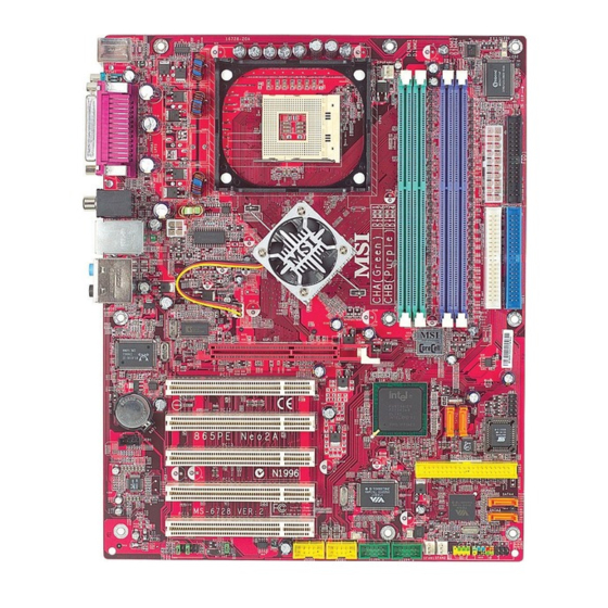
Page 12: Mainboard Layout
MS-6728 ATX Mainboard Mainboard Layout Top : mouse CPUFAN1 JCI1 Bottom: keyboard Winbond W83627HF Top : Parallel Port Bottom: COM A VGA Port (Optional) T: SPDIF Out B: USB ports JPW1 T: LAN jack (Optional) B: USB ports Intel 865PE/G Line-In Line-Out T:RS-Out... -
Page 13: Msi Special Features
MSI Special Features Super Pack (Optional) MSI provides a useful CD which includes 6 powerful and popular utilities for your office professional working and for your home leisure entertainment. 1. Adobe Photoshop Album: The fast and easy way to organize and share your lifetime photos. -
Page 14: Corecenter
MS-6728 ATX Mainboard CoreCenter (TM) CoreCenter - contains OC Menu panel, users can determine their processor and memory type to optimize its memory capacity. This all-in-one hardware console is advanced combination of the popular PC Alert and Fuzzy Logic. Including powerful function with hardware monitor, system alert and instinctive UI of overclocking, CoreCenter is just like your PC doctor that can detect, view and adjust the PC hardware and system status during real time operation. - Page 15 The exclusive OC Menu is fully de- veloped to support DDR400+ memory modules. By comprehensive validation of over 67 DDR400+ memory modules, MSI concluded best parameters for DRAM voltage, Vio and other BIOS settings. You can select DDR433, DDR450, DDR466 and DDR500 from DRAM frequency in BIOS setting.
-
Page 16: Corecell
MS-6728 ATX Mainboard Core Cell Chip By diagnosing the current system utilization, the CoreCell™ Chip automatically tunes your motherboard to the optimal state, leading to less noise, longer duration, more power- saving and higher performance. Features of CoreCell™ Speedster -- Advanced O.C. design. -- Superior O.C. -
Page 17: Color Management
Getting Started Color Management MSI has a unified color management rule for some connectors on the mainboards, which helps you to install the memory modules, expansion cards and other peripherals devices more easily and conveniently. Dual Memory DDR DIMMs: Channel A is light green, Channel B is... -
Page 18: D-Bracket™ 2 (Optional)
MS-6728 ATX Mainboard D-Bracket™ 2 (Optional) D-Bracket™ 2 is a USB bracket integrating four Diagnostic LEDs, which use graphic signal display to help users understand their system. The LEDs provide up to 16 combinations of signals to debug the system. The 4 LEDs can detect all problems that fail the system, such as VGA, RAM or other failures. - Page 19 Getting Started D-Bracket™ 2 Description Processor Initialization - This will show information regarding the processor (like brand name, system bus, etc…) Testing RTC (Real Time Clock) Initializing Video Interface - This will start detecting CPU clock, checking type of video onboard.
-
Page 20: Live Monitor
Live Monitor™ The Live Monitor™ is a tool used to schedule the search for the latest BIOS/drivers version on the MSI Web site. To use the function, you need to install the “MSI Live Update 3” application. After installation, the “MSI Live Monitor” icon (as shown on the right) will appear on the screen. -
Page 21: Live Bios™/Live Driver
Live Update 3” icon (as shown on the right) will appear on the screen. Double click the “MSI Live Update 3” icon, and the following screen will appear: Five buttons are placed on the left column of the screen. Click the desired button to start the update process. -
Page 22: Round Cable (Optional)
Connect to the slave drive. CPU Thermal Protection Aimed to prevent the CPU from overheating, MSI has developed a CPU ® Thermal Protection mechanism for Intel CPU platform. This CPU Thermal Protection mechanism works on a thermal signal sensor. If the mechanism senses an abnormal temperature rise, it will automatically shut down the system and the CPU temperature will then drop down and become normal. -
Page 23: Chapter 2. Hardware Setup
Hardware Setup Chapter 2. Hardware Setup Hardware Setup This chapter tells you how to install the CPU, memory modules, and expansion cards, as well as how to setup the jumpers on the mainboard. Also, it provides the instructions on connecting the peripheral devices, such as the mouse, keyboard, etc. -
Page 24: Quick Components Guide
MS-6728 ATX Mainboard Quick Components Guide CPUFAN1, p.2-17 CPU, p.2-3 DDR DIMMs, p.2-7 JCI1, p.2-25 ATX1, p.2-9 Back Panel I/O, p.2-10 FDD1, p.2-17 JPW1, p.2-9 NBFAN1, p.2-17 IDE1, IDE2, p.2-19 AGP Slot, p.2-27 JDB1, p.2-23 BATT SATA1, SATA2, JCD1, p.2-25 BIOS p.2-20 PCI Slots, p.2-27... -
Page 25: Central Processing Unit: Cpu
® overspecification and overclocking on Intel 865PE chipset for the list of qualified test memory modules. MSI Reminds You... Overclocking This motherboard is designed to support overclocking. However, please make sure your components are able to tolerate such abnormal setting, while doing overclocking. -
Page 26: Cpu Installation Procedures For Socket 478
MS-6728 ATX Mainboard CPU Installation Procedures for Socket 478 Please turn off the power and unplug the power cord before Open Lever installing the CPU. Pull the lever sideways away Sliding 90 degree Plate from the socket. Make sure to raise the lever up to a 90- degree angle. -
Page 27: Installing The Cpu Fan
Hardware Setup Installing the CPU Fan As processor technology pushes to faster speeds and higher performance, thermal management becomes increasingly important. To dissi- pate heat, you need to attach the CPU cooling fan and heatsink on top of the CPU. Follow the instructions below to install the Heatsink/Fan: Locate the CPU and its retention Position the heatsink onto the reten- mechanism on the motherboard. - Page 28 MS-6728 ATX Mainboard Connect the fan power cable from the mounted fan to the 3-pin fan power connec- tor on the board. fan power cable NOTES...
-
Page 29: Memory
Hardware Setup Memory The mainboard provides 4 slots for 184-pin, 2.5V DDR DIMM with 8 memory banks. You can install DDR266 / DDR333 / DDR400 / DDR433 / DDR466 / DDR500 / DDR533 SDRAM modules on the DDR DIMM slots (DIMM 1~4). To operate properly, at least one DIMM module must be installed. -
Page 30: Installing Ddr Modules
2. Insert the DIMM memory module vertically into the DIMM slot. Then push it in until the golden finger on the memory module is deeply inserted in the socket. MSI Reminds You... You can barely see the golden finger if the module is properly inserted in the socket. -
Page 31: Power Supply
Hardware Setup Power Supply The mainboard supports ATX power supply for the power system. Before inserting the power supply connector, always make sure that all components are installed properly to ensure that no damage will be caused. ATX 20-Pin Power Connector: ATX1 This connector allows you to connect to an ATX power supply. -
Page 32: Back Panel
MS-6728 ATX Mainboard Back Panel The back panel provides the following connectors: 865G Neo2-P L-in Parallel (Optional) SPDIF Out Mouse Keyboard COMA VGA Port L-out USB Ports USB Ports 865PE Neo2-P: Option 1 L-in Parallel (Optional) SPDIF Out Mouse Keyboard COMA USB Ports USB Ports... -
Page 33: Mouse Connector
Hardware Setup 865PE Neo2-P: Option 2 L-in RS-Out (Optional) SPDIF Out Mouse Parallel Keyboard COMA USB Ports USB Ports FS-Out CS-Out SPDIF Out Mouse Connector ® The mainboard provides a standard PS/2 mouse mini DIN connector for ® ® attaching a PS/2 mouse. -
Page 34: Keyboard Connector
MS-6728 ATX Mainboard Keyboard Connector ® The mainboard provides a standard PS/2 keyboard mini DIN connector ® ® for attaching a PS/2 keyboard. You can plug a PS/2 keyboard directly into this connector. PS/2 Keyboard (6-pin Female) Pin Definition SIGNAL DESCRIPTION Keyboard DATA Keyboard DATA... -
Page 35: Serial Port Connectors: Com A
Hardware Setup Serial Port Connectors: COM A The mainboard offers one 9-pin male DIN connectors as serial port COM A. The port is a 16550A high speed communication port that sends/receives16 bytes FIFOs. You can attach a serial mouse or other serial devices directly to the connectors. -
Page 36: Lan Jack: 10/100 Lan (8100C)
MS-6728 ATX Mainboard RJ-45 LAN Jack: 10/100 LAN (8100C) /Giga-bit LAN (8110S) (Optional) The mainboard provides two standard RJ-45 jacks for connection to Local Area Network (LAN). Giga-bit LAN enables data to be transferred at 1000, 100 or 10Mbps. You can connect a network cable to either LAN jack. Activity Indicator Link Indicator RJ-45 LAN Jack... -
Page 37: Audio Port Connectors (Optional)
Hardware Setup Audio Port Connectors (Optional) Depending on the mainboards you purchase, there are two options for the audio ports: three-port audio connectors for 865G Neo2-P / 865PE Neo2- P Option 1 and six-port plus SPDIF-Out for 865PE Neo2-P Option2. Line Out is a connector for Speakers or Headphones. -
Page 38: Parallel Port Connector: Lpt1
MS-6728 ATX Mainboard Parallel Port Connector: LPT1 The mainboard provides a 25-pin female centronic connector as LPT. A parallel port is a standard printer port that supports Enhanced Parallel Port (EPP) and Extended Capabilities Parallel Port (ECP) mode. Pin Definition SIGNAL DESCRIPTION STROBE... -
Page 39: Connectors
Sensor CPUFAN1 SFAN1, SFAN2 NBFAN1 MSI Reminds You... 1. Always consult the vendors for proper CPU cooling fan. 2. CPUFAN1 supports the fan control. You can install Core Center utility that will automatically control the CPU fan speed according to the actual CPU temperature. -
Page 40: Front Panel Connectors: Jfp1 & Jfp2
MS-6728 ATX Mainboard Front Panel Connectors: JFP1 & JFP2 The mainboard provides two front panel connectors for electrical con- ® nection to the front panel switches and LEDs. JFP1 is compliant with Intel Front Panel I/O Connectivity Design Guide. Reset Power Switch JFP1... -
Page 41: Ata100 Hard Disk Connectors: Ide1 & Ide2
IDE2 (Secondary IDE Connector) IDE2 can also connect a Master and a Slave drive. MSI Reminds You... If you install two hard disks on cable, you must configure the second drive to Slave mode by setting its jumper. Refer to the hard disk documentation supplied by hard disk vendors for jumper setting instructions. -
Page 42: Serial Ata/Serial Ata Raid Connectors Controlled
MS-6728 ATX Mainboard Serial ATA/Serial ATA RAID Connectors controlled by ICH5/ ICH5R: SATA1, SATA2 (Optional) The Southbridge of this mainboard is ICH5/ICH5R which supports two serial connectors SATA1& SATA2. SATA1 & SATA2 are dual high-speed Serial ATA interface ports. Each supports 1 generation serial ATA data rates of 150 MB/s. - Page 43 Optional Serial ATA cable connect to the hard disk devices Connect to serial ATA ports MSI Reminds You... Please do not fold the serial ATA cable in a 90-degree angle, for this might cause the loss of data during the transmission. 2-21...
-
Page 44: Ieee 1394 Connectors: J1394_1, J1394_2 (Optional)
MS-6728 ATX Mainboard IEEE 1394 Connectors: J1394_1, J1394_2 (Optional) The mainboard provides two 1394 pin headers that allow you to con- nect optional IEEE 1394 ports. J1394_1, J1394_2 J1394 Pin Definition SIGNAL SIGNAL TPA+ TPA- Ground Ground TPB+ TPB- Cable power Cable power Key (no pin) Ground... -
Page 45: D-Bracket™ 2 Connector: Jdb1
Hardware Setup D-Bracket™ 2 Connector: JDB1 The mainboard comes with a JDB1 connector for you to connect to D- Bracket™ 2. D-Bracket™ 2 is a USB Bracket that supports both USB1.1 & 2.0 spec. It integrates four LEDs and allows users to identify system problem through 16 various combinations of LED signals. -
Page 46: Irda Infrared Module Header: Jir1
Left channel audio signal to front panel AUD_RET_L Left channel audio signal return from front panel MSI Reminds You... If you don’t want to connect to the front audio header, pins 5 & 6, 9 & 10 have to be jumpered in order to have signal output directed to the rear audio ports. -
Page 47: Cd-In Connector: Jcd1
Hardware Setup CD-In Connector: JCD1 The connector is for CD-ROM audio connector. JCD1 GND L Chassis Intrusion Switch Connector: JCI1 This connector is connected to a 2-pin chassis switch. If the chassis is opened, the switch will be short. The system will record this status and show a warning message on the screen. -
Page 48: Jumpers
JBAT1 Keep Data Clear Data MSI Reminds You... You can clear CMOS by shorting 2-3 pin while the system is off. Then return to 1-2 pin position. Avoid clearing the CMOS while the system is on; it will damage the mainboard. -
Page 49: Slots
Hardware Setup Slots The motherboard provides one AGP slot and five 32-bit PCI bus slots. AGP (Accelerated Graphics Port) Slot The AGP slot allows you to insert the AGP graphics card. AGP is an interface specification designed for the throughput demands of 3D graphics. It introduces a 66MHz, 32-bit channel for the graphics controller to directly access main memory. -
Page 50: Chapter 3. Bios Setup
BIOS Setup Chapter 3. BIOS Setup BIOS Setup This chapter provides information on the BIOS Setup program and allows you to configure the system for optimum use. You may need to run the Setup program when: An error message appears on the screen during the system booting up, and you are requested to run SETUP. -
Page 51: Entering Setup
MS-6728 ATX Mainboard Entering Setup Power on the computer and the system will start POST (Power On Self Test) process. When the message below appears on the screen, press <DEL> key to enter Setup. DEL:Setup F11:Boot Menu F12:Network boot TAB:Logo If the message disappears before you respond and you still wish to enter Setup, restart the system by turning it OFF and On or pressing the RESET button. -
Page 52: Control Keys
BIOS Setup Control Keys <↑> Move to the previous item <↓> Move to the next item <←> Move to the item in the left hand <→> Move to the item in the right hand <Enter> Select the item <Esc> Jumps to the Exit menu or returns to the main menu from a submenu <+/PU>... -
Page 53: The Main Menu
MS-6728 ATX Mainboard The Main Menu Once you enter AMIBIOS NEW SETUP UTILITY, the Main Menu will appear on the screen. The Main Menu displays twelve configurable func- tions and two exit choices. Use arrow keys to move among the items and press <Enter>... - Page 54 BIOS Setup Integrated Peripherals Use this menu to specify your settings for integrated peripherals. PC Health Status This entry shows your PC health status. Frequency/Voltage Control Use this menu to specify your settings for frequency/voltage control. Set Supervisor Password Use this menu to set Supervisor Password. Set User Password Use this menu to set User Password.
-
Page 55: Standard Cmos Features
MS-6728 ATX Mainboard Standard CMOS Features The items inside STANDARD CMOS SETUP menu are divided into 9 categories. Each category includes none, one or more setup items. Use the arrow keys to highlight the item you want to modify and use the <PgUp> or <PgDn>... - Page 56 BIOS Setup Primary/Secondary/Third/Fourth IDE Master/Slave Press PgUp/<+> or PgDn/<-> to select the hard disk drive type. The specification of hard disk drive will show up on the right hand according to your selection. Type Select how to define the HDD parameters Cylinders Enter cylinder number Heads...
-
Page 57: Advanced Bios Features
The items allow you to set the sequence of boot devices where BIOS attempts to load the disk operating system. MSI Reminds You... Available settings for “1st/2nd/3rd Boot Device” vary depend- ing on the bootable devices you have installed. For example, if you did not install a floppy drive, the setting “Floppy”... - Page 58 BIOS Setup Try Other Boot Device Setting the option to Yes allows the system to try to boot from other devices if the system fails to boot from the 1st/2nd/3rd boot device. Full Screen LOGO Show This item enables you to show the company logo on the bootup screen. Settings are: Enabled Shows a still image (logo) on the full screen at boot.
- Page 59 This field is used to enable or disable the Hyper Threading function. Setting to Enabled will increase the system performance. Settings: Enabled, Disabled. MSI Reminds You... Enabling the functionality of Hyper-Threading Technology for your computer system requires ALL of the following platform Components: ®...
- Page 60 BIOS Setup MPS Revision This field allows you to select which MPS (Multi-Processor Specification) version to be used for the operating system. You need to select the MPS version supported by your operating system. Settings: 1.4 and 1.1. APIC ACPI SCI IRQ This field is used to enable or disable the APIC (Advanced Programmable Interrupt Controller).
-
Page 61: Advanced Chipset Features
MS-6728 ATX Mainboard Advanced Chipset Features MSI Reminds You... Change these settings only if you are familiar with the chipset. DRAM Timing Setting... Press <Enter> and to enter the sub-menu screen. Configure SDRAM Timing by SPD Selects whether DRAM timing is controlled by the SPD (Serial Presence Detect) EEPROM on the DRAM module. - Page 62 BIOS Setup CAS# Latency This controls the timing delay (in clock cycles) before SDRAM starts a read command after receiving it. Settings: 2, 2.5 (clocks). 2 (clocks) increases the system performance the most while 2.5 (clocks) provides the most stable performance. RAS# Precharge This item controls the number of cycles for Row Address Strobe (RAS) to be allowed to precharge.
- Page 63 MS-6728 ATX Mainboard dedicated to graphics memory address space. Host cycles that hit the aperture range are forwarded to the AGP without any translation. The option allows the selection of an aperture size of 4MB, 8MB, 16MB, 32MB, 64MB, 128MB, and 256 MB.
-
Page 64: Power Management Features
BIOS Setup Power Management Features APCI Standby State This item specifies the power saving modes for ACPI function. If your operat- ing system supports ACPI, such as Windows 98SE, Windows ME and Win- dows 2000, you can choose to enter the Standby mode in S1(POS) or S3(STR) fashion through the setting of this field. - Page 65 MS-6728 ATX Mainboard driver to initialize the VGA card. Therefore, if the AGP driver of the card does not support the initialization feature, the display may work abnormally or not function after resuming from S3. Power Management/APM Setting to Enabled will activate an Advanced Power Management (APM) device to enhance Max Saving mode and stop CPU internal clock.
- Page 66 BIOS Setup FDC/LPT/COM Ports, Primary/Secondary Master/Slave IDE These items specify if the BIOS will monitor the activity of the specified hardware peripherals or components. If set to Monitor, any activity detected on the specified hardware peripherals or components will wake up the system or prevent the system from entering the power saving modes.
- Page 67 Alarm Minute 00 ~ 59 Alarm Second 00 ~ 59 MSI Reminds You... If you have changed this setting, you must let the system boot up until it enters the operating system, before this function will work. Keyboard PowerOn Function This controls how the PS/2 keyboard can power on the system.
-
Page 68: Pnp/Pci Configuration
BIOS Setup PNP/PCI Configurations This section describes configuring the PCI bus system and PnP (Plug & Play) feature. PCI, or Peripheral Component Interconnect, is a system which allows I/O devices to operate at speeds nearing the speed the CPU itself uses when communicating with its special components. - Page 69 MS-6728 ATX Mainboard Init. Graphics Adapter Priority This setting specifies which VGA card is your primary graphics adapter. Setting options are: Internal VGA The system initializes the onboard VGA device. (For 865G) AGP/Int-VGA The system initializes the installed AGP card first. If an AGP card is not available, it will initialize the onboard VGA device.
- Page 70 BIOS Setup IRQ 3/4/5/7/9/10/11/14/15 These items specify the bus where the specified IRQ line is used. The settings determine if AMIBIOS should remove an IRQ from the pool of available IRQs passed to devices that are configurable by the system BIOS.
-
Page 71: Integrated Peripherals
MS-6728 ATX Mainboard Integrated Peripherals Please note that the options showed on your BIOS might be different depending on the motherboard you buy. USB Controller This setting is used to enable/disable the onboard USB controllers. USB Device Legacy Support Set to All Device if you need to use any the USB 1.1/2.0 device in the operat- ing system that does not support or have any USB 1.1/2.0 driver installed, such as DOS and SCO Unix. - Page 72 BIOS Setup On-Chip ATA(s) Operate Mode This setting allows you to determine how the RAID controller on the south bridge is going to switch to SATA controller. Legacy Mode means you may use the traditional 14 and 15 IRQs, while Native Mode means you may use all the available IRQs.
- Page 73 MS-6728 ATX Mainboard Onboard 1394 This setting controls the onboard 1394 device. Setting options: Disabled, Enabled. Onboard Serial-ATA This setting controls the onboard VIA Serial-ATA controller. Setting options: Disabled, Enabled. AC’97 Audio This item is used to enable or disable the onboard AC’97 (Audio Codec’97) feature.
- Page 74 BIOS Setup Onboard Serial Port A/B These items specify the base I/O port addresses of the onboard Serial Port 1 (COM A)/Serial Port 2 (COM B). Selecting Auto allows AMIBIOS to automatically determine the correct base I/O port address. Settings: Auto, 3F8/COM1, 2F8/COM2, 3E8/COM3, 2E8/COM4 and Disabled.
- Page 75 MS-6728 ATX Mainboard Parallel Port DMA Channel This feature needs to be configured only when Parallel Port Mode is set to the ECP mode. When Parallel Port is set to Auto, the field will show Auto indicating that BIOS automatically determines the DMA channel for the parallel port.
-
Page 76: Pc Health Status
BIOS Setup PC Health Status This section shows the status of your CPU, fan, overall system status, etc. Monitor function is available only if there is hardware monitoring mecha- nism onboard. Chassis Intrusion The field enables or disables the feature of recording the chassis intrusion status and issuing a warning message if the chassis is once opened. -
Page 77: Frequency/Voltage Control
Use this menu to specify your settings for frequency/voltage control. Dynamic OverClocking Dynamic Overclocking Technology is the automatic overclocking function, included in the MSI ’s newly developed CoreCell Technology. It is designed to detect the load balance of CPU while running programs, and to adjust the best CPU frequency automatically. - Page 78 Dynamic OverClocking first. Performance Mode This item allows you to control the MAT (memory acceleration technology) function of CPU. MAT is MSI ’s exclusive technology, specializing in opti- mizing the data transfer rate among CPU, north bridge chip and memory, and also in procuring better memory performance and bandwidth up to 10%.
- Page 79 PSB 533: 266, 333, Auto, 400, 433, 450, 466, 500, 354 (3:4). PSB 800: 266, 333, 400, Auto, 433, 450, 466, 500, 532, 501 (4:5), 533 (3:4). MSI Reminds You... The value plus a ratio (CPU: DDR) with parentheses means the non-synchronous overclocking.
- Page 80 BIOS Setup CPU Voltage (V) The setting is adjustable if you set the “CPU Vcore Adjust” to “Yes”. MSI Reminds You... Changing CPU Ratio/Vcore could result in the instability of the system; therefore, it is NOT recommended to change the default setting for long-term usage.
-
Page 81: Set Supervisor/User Password
FEATURES menu. If the PASSWORD CHECK option is set to Always, the password is required both at boot and at entry to Setup. If set to Setup, password prompt only occurs when you try to enter Setup. MSI Reminds You... About Supervisor Password & User Password: Supervisor password: Can enter and change the settings of the setup menu. -
Page 82: Load High Performance/Bios Setup Defaults
Pressing ‘Enter’ loads the default BIOS values that enable the best system performance but may lead to a stability issue. MSI Reminds You... The option is for power or overclocking users only. Use of high performance defaults will tighten most timings to increase the system performance. -
Page 83: Appendix A: Using 2-, 4- & 6-Channel Audio Function
Using 4- or 6-Channel Audio Function Appendix A: Using 2-, 4- & 6-Channel Audio Function The mainboard is equipped with Realtek ALC655 chip, which provides support for 6-channel audio output, including 2 Front, 2 Rear, 1 Center and 1 Subwoofer channel. ALC655 allows the board to attach 4 or 6 speakers for better surround sound effect. -
Page 84: Installing The Audio Driver
1. Insert the companion CD into the CD-ROM drive. The setup screen will automatically appear. 2. Click Realtek AC97 Audio Drivers. Click here MSI Reminds You... The AC97 Audio Configuration software utility is under continuous update to enhance audio applications. Hence, the... - Page 85 Using 4- or 6-Channel Audio Function 3. Click Next to install the AC’97 Audio software. Click here 4. Click Finish to restart the system. Select this option Click here...
-
Page 86: Software Configuration
MS-6728 ATX Mainboard Software Configuration After installing the audio driver, you are able to use the 4-/6-channel audio feature now. Click the audio icon from the window tray at the lower- right corner of the screen to activate the AC97 Audio Configuration. Sound Effect Here you can select a sound effect you like from the Environment list. - Page 87 Using 4- or 6-Channel Audio Function Here it provides the Karaoke function which will automatically remove human voice (lyrics) and leave melody for you to sing the song. Note that this function applies only for 2-channel audio operation. Just check the Voice Cancellation box and then click OK to activate the Karaoke function.
-
Page 88: Equalizer
MS-6728 ATX Mainboard Equalizer Here you regulate each equalizer for current playing digital sound sources. You may choose the provided sound effects, and the equalizer will adjust automatically. If you like, you may also load an equalizer setting or make an new equalizer setting to save as an new one by using the buttons Load and Save. -
Page 89: Speaker Configuration
Using 4- or 6-Channel Audio Function Speaker Configuration In this tab, you can easily configure your multi-channel audio function and speakers. 1. Select the audio configuration below which is identical to the audio jack in your mainboard. Since the audio port for this 865PE/G Neo2-P mainboard is optional, you will have to choose either 6CH+ S/PDIF (Coaxial) (for 865G Neo2-P &... - Page 90 MS-6728 ATX Mainboard 2. Select a desired multi-channel operation from Number of Speaker. a. Headphone for the common headphone b. 2-Channel Mode for Stereo-Speaker Output c. 4-Channel Mode for 4-Speaker Output d. 6-Channel Mode for 5.1-Speaker Output 3. Here it shows the multi-channel setting for the audio jack. Please connect your speakers to the correct phone jack in accordance with the setting displayed here.
-
Page 91: Speaker Test
Using 4- or 6-Channel Audio Function Speaker Test You can use this tab to test each connected speaker to ensure if 4- or 6- channel audio operation works properly. If any speaker fails to make sound, then check whether the cable is inserted firmly to the connector or replace the bad speakers with good ones. - Page 92 MS-6728 ATX Mainboard MSI Reminds You... 1. 6 speakers appear on the “Speaker Test” tab only when you select “6-Channel Mode” in the “Number of Speakers” col- umn in “Speaker Configuration” tab. If you select “4-Chan- nel Mode”, only 4 speakers appear on the window.
-
Page 93: Hrtf Demo
Using 4- or 6-Channel Audio Function HRTF Demo In this tab you may adjust your HRTF (Head Related Transfer Functions) 3D positional audio before playing 3D audio applications like gaming. You may also select different environment to choose the most suitable environment you like. -
Page 94: General
MS-6728 ATX Mainboard General In this tab it provides some information about this AC97 Audio Configu- ration utility, including Audio Driver Version, DirectX Version, Audio Control- ler & AC97 Codec. You may also select the language of this utility by choosing from the Language list. -
Page 95: Using 2-, 4- & 6- Channel Audio Function
Using 4- or 6-Channel Audio Function Using 2-, 4- & 6- Channel Audio Function For 865G Neo2-P and 865PE Neo2-P Option 1: Connecting the Speakers When you have set the Multi-Channel Audio Function mode properly in the software utility, connect your speakers to the correct phone jacks in accordance with the setting in software utility. - Page 96 MS-6728 ATX Mainboard 4-Channel Mode for 4-Speaker Output The audio jacks on the back panel always provide 2-channel analog audio output function, however these audio jacks can be transformed to 4- or 6- channel analog audio jacks by selecting the corresponding multi-channel operation from No.
- Page 97 Out function when 6-Channel Mode for 6-Speaker Output is selected. MSI Reminds You... If the audio signals coming from the Center and Subwoofer speaker are swapped when you play video or music on the computer, a converter may be required to exchange center and subwoofer audio signals.
-
Page 98: For 865Pe Neo2-P Option 2
MS-6728 ATX Mainboard For 865PE Neo2-P Option 2: Connecting the Speakers When you have set the Multi-Channel Audio Function mode properly in the software utility, connect your speakers to the correct phone jacks in accordance with the setting in software utility. 2-Channel Mode for Stereo-Speaker Output Refer to the following diagram and caption for the function of each phone jack on the back panel when 2-Channel Mode is selected. - Page 99 Using 4- or 6-Channel Audio Function 4-Channel Mode for 4-Speaker Output Back Panel 4-Channel Analog Audio Output Line In Line Out (Front channels) Line Out (Rear channels) Line Out (Center and Subwoofer channel, but no functioning in this mode) SPDIF Out Optical jack SPDIF Out Coaxial jack A-17...
- Page 100 MS-6728 ATX Mainboard 6-Channel Mode for 4-Speaker Output Back Panel 6-Channel Analog Audio Output Line In Line Out (Front channels) Line Out (Rear channels) Line Out (Center and Subwoofer channel) SPDIF-Out Optical jack SPDIF-Out Coaxial jack A-18...
-
Page 101: Appendix B. Intel Ich5R Serial Ata Raid Introduction
1. Supports 150 MB/s transfers with CRC error checking 2. Data handling optimizations including tagged command queuing, elevator seek and packet chain command MSI Reminds You... All the information/volumes listed in your system might differ from the illustrations in this appendix. -
Page 102: Introduction
--- Comprehend both Legacy and/or Native Modes. --- Maximum 6 ATA devices to connect (4 for P-ATA & 2 for S-ATA). MSI Reminds You... BIOS provides a BIOS setup option for Native Mode or Legacy Mode user selection. Please refer to P.3-23 On-Chip IDE... - Page 103 Intel ICH5R Serial ATA RAID Introduction What is RAID 0 (striping)? RAID 0 leverages the read/write capabilities of two or more hard drives working in unison to maximize the storage performance of a computer system. Data in a RAID 0 volume is arranged into blocks that are interleaved among the disks so that reads and writes can be performed in parallel (see below diagram).
- Page 104 MS-6728 ATX Mainboard What is RAID 1 (mirroring)? A RAID 1 array contains two hard drives where the data between the two is mirrored in real time. Since all of the data is duplicated, the operating system treats the usable space of a RAID 1 array as the maximum size of one hard drive in the array.
-
Page 105: Bios Configuration
Configuration utility stored within the Intel RAID Option ROM. During the Power-On Self Test (POST), the following message will appear for a few seconds: MSI Reminds You... The “Driver Model”, “Serial #” and “Size” in the following example might be different from your system. - Page 106 1. Select option 1 “Create RAID Volume” and press <Enter> key. The following screen appears: MSI Reminds You... The following procedure is only available with a newly-built system or if you are reinstalling your OS. It should not be used to...
- Page 107 Intel ICH5R Serial ATA RAID Introduction 2. Specify a RAID Volume name and then press the <TAB> or <Enter> key to go to the next field. 3. Select the strip value for the RAID 0 or RAID 1 array by using the “upper arrow”...
- Page 108 MS-6728 ATX Mainboard 4. From the Strip size, press the <Tab> or <ENTER> key to advance to the Create Volume prompt. The window will appear as follows: 5. Then press <Enter> to create the specified volume and the following prompt will show:...
- Page 109 Intel ICH5R Serial ATA RAID Introduction 6. Press <Y> to confirm the selection or press <N> to create the RAID volume again. Then you will return to the main menu with an updated status as follows: 7. Scroll to option 4 Exit and press <Enter> to exit the RAID Configuration utility.
- Page 110 Here you can delete the RAID volume, but please be noted that all data on RAID drives will be lost. MSI Reminds You... If your system currently boots to RAID and you delete the RAID volume in the Intel RAID Option ROM, your system will become unbootable.
- Page 111 Intel ICH5R Serial ATA RAID Introduction Select the volume and press <Delete> key to delete the RAID volume. The following prompt appears: Press <Y> key to accept the volume deletion. B-11...
- Page 112 RAID volume and remove any RAID structures from the drives. The following screen appears: Press <Y> key to accept the selection. MSI Reminds You... 1. You will lost all data on the RAID drives and any internal RAID structures when you perform this operation.
-
Page 113: Installing Software
Windows XP installation. Existing Windows XP / 2000 Driver Installation 1. Insert the MSI CD into the CD-ROM drive. 2. The CD will auto-run and the setup screen will appear. 3. Under the Driver tab, click on Intel IAA RAID Edition. - Page 114 Intel Application Accelerator RAID Edition utility Help documentation Start menu shortcuts and system tray icon service RAID Monitor service Insert the MSI CD and click on the Intel IAA RAID Edition to install the software. Click the Intel IAA RAID Edition...
- Page 115 Intel ICH5R Serial ATA RAID Introduction The InstallShield Wizard will begin automatically for installation showed as following: Click on the Next button to proceed the installation in the welcoming window. B-15...
- Page 116 MS-6728 ATX Mainboard The window shows the components to be installed. Click Next button to continue. After reading the license agreement in the following window, click Yes button to continue. B-16...
- Page 117 Intel ICH5R Serial ATA RAID Introduction Select the folder in which you want the program to be installed in the following window, and click Next button to start installation. Select a program folder in the following window where you want Setup to add the program icon.
- Page 118 MS-6728 ATX Mainboard The following window appears to show the Intel Application Accelerator RAID Edition Setup installation status. Once the installation is complete, the following window appears. B-18...
-
Page 119: Raid Migration Instructions
To create a volume from an existing disk, complete the following steps: MSI Reminds You... A Create from Existing Disk operation will delete all existing data from the added disk and the data cannot be recovered. It is critical to backup all important data on the added disk before proceeding. - Page 120 MS-6728 ATX Mainboard Create RAID Volume from Existing Disk To create a RAID volume from an existing disk, right-mouse click on RAID Volume and select Create From Existing Disk to create a new RAID volume as the screen below. You may also use the RAID drop-down menu and click on Create Volume from Existing Disk.
- Page 121 Intel ICH5R Serial ATA RAID Introduction (2) Step 2 of 3: Select the RAID Volume Name and Strip Size In Step 2, select the RAID volume name and strip size, and click Next: RAID Volume Name: A desired RAID volume name needs to be typed in where the ‘RAID_Volume1’ text currently appears above.
- Page 122 MS-6728 ATX Mainboard 32KB: Good for sequential transfers 64KB: Good general purpose strip size 128KB: Best performance for most desktops and workstations Before you continue to Step 3 of 3 by clicking Next in Step 2 of 3, read the next 2 dialogue boxes carefully.
- Page 123 Intel ICH5R Serial ATA RAID Introduction Migration Process The migration process may take up to two hours to complete depending on the size of the disks being used and the strip size selected. A dialog window will appear stating that the migration process may take considerable time to complete and you must click Yes in order to start the migration.
-
Page 124: Appendixc. Via Vt6420 Serial Ata Raid Introduction
VIA VT6420 Serial ATA RAID Introduction Appendix. Using 4- or 6-Channel Appendix C: VIA VT6420 Serial ATA Audio Function RAID Introduction VIA VT6420 provides a hybrid solution that combines two independent SATA ports for support of up to two Serial ATA (Serial ATA RAID) drives. Serial ATA (SATA) is the latest generation of the ATA interface. -
Page 125: Introduction
MS-6728 ATX Mainboard Introduction This section gives a brief introduction on the RAID-related background knowledge and a brief introduction on VIA SATA RAID Host Controller. For users wishing to install their VIA SATA RAID driver and RAID software, proceed to Driver and RAID Software Installation section. RAID Basics RAID (Redundant Array of Independent Disks) is a method of combin- ing two or more hard disk drives into one logical unit. - Page 126 VIA VT6420 Serial ATA RAID Introduction RAID 0 (Striping) RAID 0 reads and writes sectors of data interleaved between multiple drives. If any disk member fails, it affects the entire array. The disk array data capacity is equal to the number of drive members times the capacity of the smallest member.
-
Page 127: Bios Configuration
MS-6728 ATX Mainboard BIOS Configuration When the system powers on during the POST (Power-On Self Test) process, press <Tab> key to enter the BIOS configuration. The Serial ATA RAID volume may be configured using the VIA Tech. RAID BIOS. Always use the arrow keys to navigate the main menu, use up and down arrow key to select the each item and press <Enter>... -
Page 128: Create Disk Array
Create Disk Array Use the up and down arrow keys to select the Create Array command and press <Enter>. MSI Reminds You... The “Channel”, “Drive Name”, “Mode” and “Size (GB)” in the following example might be different from your system. - Page 129 MS-6728 ATX Mainboard After array mode is selected, there are two methods to create a disk array. One method is “Auto Setup” and the other one is “Select Disk Drives”. Auto Setup allows BIOS to select the disk drives and create arrays automatically, but it does not duplicate the mirroring drives even if the user selected Create and duplicate for RAID 1.
- Page 130 VIA VT6420 Serial ATA RAID Introduction MSI Reminds You... Even though 64KB is the recommended setting for most users, you should choose the block size value which is best suited to your specific RAID usage model. 4KB: For specialized usage models requiring 4KB blocks...
-
Page 131: Delete Disk Array
MS-6728 ATX Mainboard Delete Disk Array A RAID can be deleted after it has been created. To delete a RAID, use the following steps: 1. Select Delete Array in the main menu and press <Enter>. The channel column will be activated. 2. -
Page 132: Create And Delete Spare Hard Drive
VIA VT6420 Serial ATA RAID Introduction Create and Delete Spare Hard Drive If a RAID 1 array is created and there are drives that do not belong to other arrays, the one that has a capacity which is equal to or greater than the array capacity can be selected as a spare drive for the RAID 1 array. -
Page 133: Select Boot Array
MS-6728 ATX Mainboard Select Boot Array User can select a disk array as boot device if user wants to boot operating system from an array. Boot disk array cannot be selected if the operating system does not boot from the disk array. Highlight the Select Boot Array item;... -
Page 134: View Serial Number Of Hard Drive
VIA VT6420 Serial ATA RAID Introduction View Serial Number of Hard Drive Highlight Serial Number View and press <Enter>. Use arrow key to select a drive, the selected drive’s serial number can be viewed in the last column. The serial number is assigned by the disk drive manufacturer. Press the F1 key to show the array status on the lower screen. -
Page 135: Duplicate Critical Raid 1 Array
MS-6728 ATX Mainboard Duplicate Critical RAID 1 Array When booting up the system, BIOS will detect if the RAID 1 array has any inconsistencies between user data and backup data. If BIOS detects any inconsistencies, the status of the disk array will be marked as critical, and BIOS will prompt the user to duplicate the RAID 1 in order to ensure the backup data consistency with the user data. -
Page 136: Rebuild Broken Raid 1 Array
VIA VT6420 Serial ATA RAID Introduction Rebuild Broken RAID 1 Array When booting up the system, BIOS will detect if any member disk drives of RAID has failed or is absent. If BIOS detects any disk drive failures or missing disk drives, the status of the array will be marked as broken. If BIOS detects a broken RAID 1 array but there is a spare hard drive available for rebuilding the broken array, the spare hard drive will automatically become the mirroring drive. - Page 137 MS-6728 ATX Mainboard 3. Choose Replacement Drive and Rebuild: This item enables users to select an already-connected hard drive to rebuild the broken array. After choosing a hard drive, the channel column will be activated. Highlight the target hard drive and press <Enter>, a warning message will appear.
-
Page 138: Installing Raid Software & Drivers
Windows XP installation Existing Windows XP Driver Installation 1. Insert the MSI CD into the CD-ROM drive. 2. The CD will auto-run and the setup screen will appear. 3. Under the Driver tab, click on VIA SATA RAID Utility. -
Page 139: Installation Of Via Sata Raid Utility
VIA SATA RAID Utility contains the following key features: Serial ATA RAID driver for Windows XP VIA SATA RAID utility RAID0 and RAID1 functions Insert the MSI CD and click on the VIA SATA RAID Utility to install the software. C-16... - Page 140 VIA VT6420 Serial ATA RAID Introduction The InstallShield Wizard will begin automatically for installation. Click on the Next button to proceed the installation in the welcoming window. Put a check mark in the check box to install the feature you want. Then click Next button to proceed the installation.
-
Page 141: Using Via Raid Tool
MS-6728 ATX Mainboard Using VIA RAID Tool Once the installation is complete, go to Start ---> Programs --->VIA -- ->raid_tool.exe to enable VIA RAID Tool. After the software is finished installation, it will automatically started every time Windows is initiated. You may double-click on the icon shown in the system tray of the tool bar to launch the VIA RAID Tool utility. - Page 142 VIA VT6420 Serial ATA RAID Introduction The main interface is divided into two windows and the toolbar above contain the main functions. Click on these toolbar buttons to execute their specific functions. The left windowpane displays the controller and disk drives and the right windowpane displays the details of the controller or disk drives.
- Page 143 MS-6728 ATX Mainboard Click on the plus (+) symbol next to Array 0---RAID 0 to see the details of each disk. You may also use the same button to view the statuses of Array 0---RAID 1. C-20...
- Page 144 VIA VT6420 Serial ATA RAID Introduction Click on the plus (+) symbol next to Array 0---RAID 1 to see the details of each disk. C-21...
-
Page 145: Overclocking On Intel ® 865Pe Chipset
The explanation for overspecification and overclocking Appendix D: The explanation for overspecification and ® overclocking on Intel 865PE chipset ® The default specification of Intel 865PE chipset is only able to support FSB 400/533MHz CPU and DDR 266/333/400 DRAM technology. However, we have spent engineering efforts to allow the overspecification and overclocking of 865PE Neo2-P under certain conditions. - Page 146 C If the frequency after overclocking is not stable, you may fine-tune the settings of ‘CPU Voltage” and “DDR Power Voltage” by adjusting to a higher value. MSI Reminds You... Please refer to p. 3-28 Frequency/Voltage Control for the details of BIOS settings.
- Page 147 The explanation for overspecification and overclocking 3. System configuration and DDR 400/PC 3200 Qualified Memory Test List When using DDR400 memory modules, a maximum of 2 DIMMs are recommended. Please refer to the system configuration and DDR400/PC3200 DIMMs listed below for overclocking. Table 1: System Configuration System Configuration Manufacturer...
- Page 148 MS-6728 ATX Mainboard Table 2: DDR433/466/500 Memory Test List M e m . D D R M e m o r y M e m o r y R .S .T M o d e l S iz e S lo t B a n d w id th B e n c h m a r k √...