Table of Contents
Advertisement
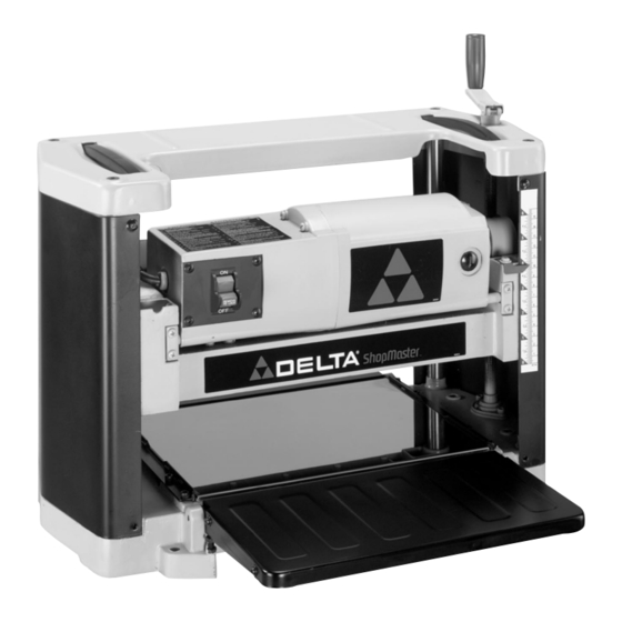
12" Portable Planer
(Model TP300)
PART NO. 909543 - 05-01-03
Copyright © 2003 Delta Machinery
To learn more about DELTA MACHINERY
ESPAÑOL: PÁGINA 17
visit our website at: www.deltamachinery.com.
For Parts, Service, Warranty or other Assistance,
1-800-223-7278 (
1-800-463-3582).
please call
In Canada call
Advertisement
Table of Contents

Related Manuals for Delta ShopMaster TP300


Summary of Contents for Delta ShopMaster TP300
- Page 1 12" Portable Planer (Model TP300) PART NO. 909543 - 05-01-03 Copyright © 2003 Delta Machinery To learn more about DELTA MACHINERY ESPAÑOL: PÁGINA 17 visit our website at: www.deltamachinery.com. For Parts, Service, Warranty or other Assistance, 1-800-223-7278 ( 1-800-463-3582). please call...
-
Page 2: Safety Guidelines - Definitions
If you have any questions relative to a particular application, DO NOT use the machine until you have first contacted Delta to determine if it can or should be performed on the product. - Page 3 READ USE RECOMMENDED ACCESSORIES. The use of accessories and attachments not recom- mended by Delta may cause damage to the machine or injury to the user. USE THE PROPER EXTENSION CORD. Make sure your extension cord is in good condition.
- Page 4 4. MAKE all adjustments with the power off. 5. DISCONNECT machine from power source when making repairs. 6. NEVER turn the planer “ON” before clearing the table of all objects (tools, scraps of wood, etc.). 7. KEEP knives sharp and free of all rust and pitch.
-
Page 5: Power Connections
A separate electrical circuit should be used for your machines. This circuit should not be less than #12 wire and should be protected with a 20 Amp time lag fuse. If an extension cord is used, use only 3-wire extension cords which have 3- prong grounding type plugs and matching receptacle which will accept the machine’s plug. -
Page 6: Extension Cords
FUNCTIONAL DESCRIPTION FOREWORD Delta ShopMaster Model TP300 is a 12" (305mm) Portable Planer. It has the following cutting capacity; 12" (305mm) width , 6" (152mm) thickness and 3/32" (2.4mm) depth of cut. Features include; basic machine with powerful 15 amp, 120 volt motor, two-knife cutterhead with a set of high-speed steel double-edged reversible knives;... - Page 7 PLANER PARTS Fig. 2 Fig. 3 1 - 12" Planer 2 - Chip Deflector 3 - Knife Setting Gage 4 - 8mm and 10mm Open-End Wrench 5 - M5 x 20mm Hex Socket Head Screw 6 - M5 Wing Nut (2)
- Page 8 The infeed and outfeed extension tables (A) Fig. 6, are shipped attached to the machine in the raised position. Lower the tables (A) on both sides of the planer as shown in Fig. 6. The top surface of extension tables should be level with the planer table.
-
Page 9: Chip Deflector
CHIP DEFLECTOR 1. Assemble chip deflector (A) Fig. 7, to the planer by inserting end of chip deflector over the top of the cutterhead. Make certain the two screws, one of which is shown at (B) are inserted upward through the two slots (C) in the chip deflector. -
Page 10: Operating Controls And Adjustments
(B). NOTE: One revolution of the handle will move the cutterhead up or down approximately 5/64". An English/metric scale (C) and pointer (D) is located on the side of the planer for ease in setting the height of the cutterhead. RECOMMENDED... -
Page 11: Storing The Power Cord
To check the extension tables and adjust if necessary, proceed as follows: 1. Place a straight edge (B) Fig. 17, on the planer table (A) with one end extending out over the extension table as shown. Check to see if the infeed table is level with the planer table on both ends of the planer table. -
Page 12: Replacing And Resetting Knives
Fig. 21 Fig. 22 4. If an adjustment to one or both knives is necessary, slightly loosen the seven locking screws, six of which are shown at (C) Fig. 21, by turning the screws CLOCKWISE into the knife locking bar just enough to relieve stress in the cutterhead and not disturb the knife setting. -
Page 13: Operation
2. Plane to Thickness – Place the side you just surfaced in STEP 1 face down and feed the board through the planer, as shown in Fig. 25, plane until this side is flat. Then plane both sides of the board until you are satisfied with the thickness, making thin cuts, alternating sides with each pass. -
Page 14: Maintenance
(C) Fig. 29, and a light coat of spray lubricant on the chains (F). Replace the side cover. 3. Lay the planer on its back and squirt oil on the feed roller bushings (D) Fig. 30, at each end of the feed rollers (E). - Page 15 NOTES...
-
Page 16: Parts, Service Or Warranty Assistance
Two Year Limited New Product Warranty Delta will repair or replace, at its expense and at its option, any new Delta machine, machine part, or machine accessory which in normal use has proven to be defective in workmanship or material, provided that the customer returns the product prepaid to a Delta factory service center or authorized service station with proof of purchase of the product within two years and provides Delta with reasonable opportunity to verify the alleged defect by inspection. - Page 17 Delta products should be obtained by contacting any Porter-Cable · Service Center, or Porter-Cable Delta Factory Service Center. If you do not have access to any of these, call 800-223-7278 and you will · be directed to the nearest Porter-Cable Delta Factory Service Center.