Table of Contents
Advertisement
Available languages
Available languages
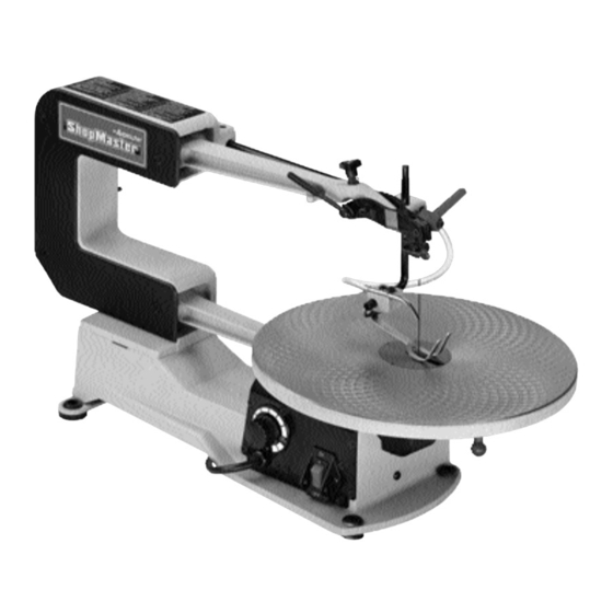
16" Variable Speed Scroll Saw
¤
with Quickset II
Blade
Changing Feature
(Model SM600)
PART NO. 638519-00 10-30-05
Copyright © 2005 Delta Machinery
To learn more about DELTA MACHINERY
ESPA OL: P GINA 21
visit our website at: www.deltamachinery.com.
FRAN AIS: PAGE 41
For Parts, Service, Warranty or other Assistance,
1-800-223-7278 (
1-800-463-3582).
please call
In Canada call
Advertisement
Table of Contents

Related Manuals for Delta 16 SM600


Summary of Contents for Delta 16 SM600
- Page 1 Changing Feature (Model SM600) PART NO. 638519-00 10-30-05 Copyright © 2005 Delta Machinery To learn more about DELTA MACHINERY ESPA OL: P GINA 21 visit our website at: www.deltamachinery.com. FRAN AIS: PAGE 41 For Parts, Service, Warranty or other Assistance, 1-800-223-7278 ( 1-800-463-3582).
-
Page 2: General Safety Rules
If you have any questions relative to a particular application, DO NOT use the machine until you have first contacted Delta to determine if it can or should be performed on the product. -
Page 3: Additional Safety Rules For Scroll Saws
Wedge open the kerf and back blade out of the workpiece. 18. THE USE of attachments and accessories not recommended by Delta may result in the risk of injuries. 19. ALWAYS hold the work firmly against the table. 20. DO NOT feed the material too fast while cutting. Only feed the material fast enough so that the blade will cut. -
Page 4: Power Connections
A separate electrical circuit should be used for your machines. This circuit should not be less than #12 wire and should be protected with a 20 Amp time lag fuse. If an extension cord is used, use only 3-wire extension cords which have 3- prong grounding type plugs and matching receptacle which will accept the machine’s plug. -
Page 5: Extension Cords
WARNING: Use proper extension cords. Make sure your extension cord is in good condition and is a 3-wire extension cord which has a 3-prong grounding type plug and matching receptacle which will accept the machine’s plug. When using an extension cord, be sure to use one heavy enough to carry the current of the machine. An undersized cord will cause a drop in line voltage, resulting in loss of power and overheating. - Page 6 Fig. 1 Fig. 1 1. Scroll Saw with blade attached SCROLL SAW PARTS Fig. 2 2. Table 3. Quickset Blade Changing Wrench 4. Holddown Rod 5. 4mm Hex Wrench 6. Locking Handle 7. M10 Flat Washer 8. Blank Table Insert 9.
- Page 7 For your own safety, do not connect the machine to the power source until the machine is completely assembled and you read and understand the entire instruction manual. 1.) 4mm hex wrench - supplied 2.) Quickset Blade Changing Wrench - supplied 1.
- Page 8 5. Position table (A) Fig. 7, on the machine as shown. Align the two holes in the table trunnions (O) with the two holes in the base (P) of the machine. NOTE: BEFORE TIGHTENING THE M6x1x45mm SPECIAL SCREWS (B) AND M6 LOCKNUTS (C) FIG. 7, MAKE SURE THE TILT SCALE (D), IS POSITIONED INSIDE POINTER (E) AS SHOWN.
- Page 9 9. Using the 4mm wrench (L) Fig. 11, loosen the two screws (P) on bottom of bracket (M) that fasten bracket to rod (N). 10. Rotate bracket (M), to the position shown in Fig. 12. Loosen lock handle (R) and insert holddown rod (S) into hole in bracket (M), as shown.
-
Page 10: Fastening Scroll Saw To Supporting Surface
FASTENING SCROLL SAW TO SUPPORTING SURFACE WARNING: Your scroll saw MUST be securely fastened to a stand or workbench using the holes in the four rubber feet, three of which are shown at (A) Fig. 16. IMPORTANT: When mounting the saw to a stand or workbench DO NOT over-tighten mounting bolts. -
Page 11: Changing Blades
TABLE INSERT The table insert (A) can be assembled to the saw table with the opening in the insert pointing to the front of the table, as shown in Fig. 19, or to the right as shown in Fig. With the table in the level position, 90 degrees to the blade, the insert should be positioned, as shown in Fig. - Page 12 3. Push chuck locking lever (C) Fig. 23, to the rear as shown. This will release the blade (D) from the upper chuck (E). 4. Insert long end (F) Fig. 24, of quickset blade wrench into hole (G) in lower blade holder. This will align wrench (H) with blade holder screw (J).
-
Page 13: Adjusting Blade Tension
ADJUSTING BLADE TENSION Tension is applied to the blade when the blade tension lever (A) Fig. 27, is in the rear position, as shown. When the lever (A) is moved forward, as shown in Fig. 28, blade tension is released. When adjusting blade tension, lever (A) should be in the forward position, as shown in Fig. -
Page 14: Tilting The Table
TILTING THE TABLE The table on your scroll saw can be tilted 45 degrees to the left for bevel cutting operations by loosening table lock handle (A) Fig. 30, tilt the table to the desired angle and tighten lock handle (A). When bevel cutting, the holddown (B) Fig. -
Page 15: Adjusting Holddown
ADJUSTING HOLDDOWN The holddown (A) Fig. 34, should be adjusted so it contacts the top surface of the work being cut by loosening lock handle (B) and moving holddown rod (C) up or down. Then tighten lock handle (B). ADJUSTING DUST BLOWER The dust blower (A) Fig. -
Page 16: Following A Line
WARNING: CUT HAZARD: Keep hands away from blade. With your scroll saw you should be able to cut a straight or curved line with ease. Most beginners will experience blade wandering; however, they eventually learn to control it as they become more familiar with the machine. Use scrap material to practice cuts before starting a project. This enables you to develop your own way of cutting and you will find out what you can and cannot do with your saw. -
Page 17: Choice Of Blade And Speed
LUBRICATION It is recommended that the scroll saw be oiled after each 20 hours of use, as follows: WARNING: DISCONNECT MACHINE FROM POWER SOURCE. 2. Remove four screws (A) Fig. 39, and remove side panel (B) from the scroll saw. 3. - Page 18 NOTES...
- Page 19 NOTES...
-
Page 20: Parts, Service Or Warranty Assistance
1-800-223-7278 (In Canada call 1-800-463-3582). Delta will repair or replace, at its expense and at its option, any Delta machine, machine part, or machine accessory which in normal use has proven to be defective in workmanship or material, provided that the customer returns the product prepaid to a Delta factory service center or authorized service station with proof of purchase of the product within two years and provides Delta with reasonable opportunity to verify the alleged defect by inspection. - Page 21 16 pulg. de Velocidad Variable (Modelo SM600) 638519-00 - 10-30-05 Copyright © 2005 Delta Machinery Para obtener más información sobre Delta Machinery, ENGLISH: PAGE 1 visite nuestro sitio web en: www.deltamachinery.com Para las piezas, el servicio, la garant a o la otra ayuda...
-
Page 22: Normas De Seguridad Generales
Si tiene cualquier pregunta con respecto a un uso específico, NO UTILICE la máquina hasta haberse comunicado con Delta para determinar si se puede o si se debe realizar sobre el producto. - Page 23 Abra la entalladura con una cuña y retire la hoja de la pieza. 18. EL USO de accesorios que no sean los recomendados por Delta puede resultar en el riesgo de lesionamientos. 19. SOSTENGA la pieza firmemente contra la mesa SIEMPRE.
-
Page 24: Especificaciones Del Motor
CONEXIONES A LA FUENTE DE ALIMENTA C I N Debe utilizarse un circuito eléctrico independiente para las máquinas. Este circuito debe tener alambre de no menos del No. 12 y debe estar protegido con un fusible de acción retardada de 20 A. Si se utiliza un cordón de extensión, utilice únicamente cordones de extensión de tres alambres que tengan enchufes de tipo de conexión a tierra con tres terminales y un receptáculo coincidente que acepte el enchufe de la máquina. -
Page 25: Instrucciones De Funcionamiento
PREFACIO El delta ShopMaster SM600 modelo es una sierra de la voluta de la velocidad de la variable del 16". La gama variable de la velocidad para el modelo SM600 es 400-1800 movimientos que cortan por minuto. El modelo SM600 ofrece una profundidad completa del 2"del corte para los objetos gruesos. - Page 26 SIERRA DE CALAR DE PIEZAS Fig. 1 Fig. 1 1. Sierra de la voluta con la lámina unida Fig. 2 Fig. 2 2. Mesa 3. Llave Que cambia De la Lámina De Quickset 4. Abrazadera de sujeción Barra 5. Llave De Tuerca hexagonal De 4mm 6.
- Page 27 1. Para quitar la lámina de la sierra de la voluta, siga de la forma siguiente. 2. Mueva la fig. 3 de la manija de la tensión de la palanca de la lámina (A), a la posición de la advertencia según lo demostrado.
- Page 28 5. Coloque la mesa, (A) Figura 7, sobre la máquina de la manera ilustrada. Ponga en línea los dos hoyos en los muñones de la mesa, (O), con los dos hoyos en la base (P) de la máquina, utilizando los dos tornillos especiales (B) y las tuercas de cierre (C) de la manera ilustrada.
- Page 29 9. Utilizando la llave que se proporciona (L) Figura 11, afloje los dos tornillos en el fondo del soporte (M), que fijan el soporte a la varilla (N). 10. Gire el soporte (M) a la posición ilustrada en la Figura 12. Afloje la agarradera de cierre (R) e inserte la varilla de sujeción (S) en el hoyo del soporte (M) de la manera ilustrada.
- Page 30 APAGADO mediante el uso de un candado (C), como se ilustra en la Fig. 18. El candado que se muestra en (C) se dispone de Delta. interruptor Fig. 16 Fig. 17 Fig. 18...
-
Page 31: Cambio De Hojas
PIEZA DE RELLENO DE LA MESA La pieza inserta de la mesa (A) puede ensamblarse a la mesa de la sierra con la abertura en la pieza apuntando hacia el frente de la mesa, de la manera ilustrada en la Figura 19, o a la derecha, en la Figura 20. - Page 32 3. Oprima la palanca de cierre del mandrino de apriete, (C) Figura 23, hacia atrás de la manera ilustrada. Esto soltará la hoja (D) automáticamente del mandrino superior (E). 4. Inserte el extremo largo, (F) Figura 24, de la llave de cambio para la hoja de fijación rápida en el hoyo (G) en detentor hoja...
- Page 33 AJUSTANDO LA TENSION DE HOJA La tensión se aplica a la hoja cuando la palanca de tensión de hoja (A) Figura 27, se encuentra en la posición trasera, como se enseña aquí. Cuando la palanca (A) es movida hacia adelante, como aparece en la Figura 28, se suelta la tensión de hoja.
- Page 34 INCLINADO DE LA MESA La mesa de su sierra de calar puede ser inclinada 45 grados hacia la izquierda para las operaciones de cortado de biselado al aflojar la agarradera del cierre de mesa (A) Figura 30. Incline la mesa al ángulo deseado y vuelva a apretar la agarradera del cierre de mesa (A).
- Page 35 AJUSTE DEL RETEN El retén, (A) Figura 34, debería ajustarse de manera que haga contacto con la superficie superior de la pieza a cortar, aflojando la agarradera de cierre (B) y moviendo la varilla de retén (C) hacia arriba o hacia abajo. Vuelva a apretar entonces la agarradera de cierre (B).
- Page 36 El cortado interior toma lugar cuando la hoja debe ser roscada a través de un hoyo en la pieza de trabajo. La Sierra de Calar Delta de 16" es capaz de realizar esta operación rápida y fácilmente, de la siguiente manera: Supongamos que usted está...
- Page 37 LUBRICACION Para mantener la sierra de calar funcionando a un máximo de eficiencia, recomendamos que se lleve a cabo un sencillo procedimiento de mantenimiento luego de cada 20 horas de uso, aproximadamente. Prosiga de la siguiente manera: 1. ASEGURESE QUE LA MAQUINA ESTE DES- CONECTADA DE LA FUENTE DE POTENCIA.
- Page 38 NOTAS...
- Page 39 1-800-223-7278 (en la llamada 1-800-463-3582 de Canadá). Delta reparar o repondr a gasto y opci n propia cualquier m quina, pieza de maquinaria o accesorio de m quina Delta que haya sido encontrado defectuoso en su fabricaci n o material durante el transcurso del uso normal, siempre que el cliente devuelva el producto pagado por adelantado a un centro de servicio en una f brica de Delta o autorizado por Delta dentro de dos a os y proporcione a Delta una oportunidad suficiente como para verificar el alegado defecto por inspecci n.
- Page 41 (modèle SM600) 638519-00 10-30-05 Copyright © 2005 Delta Machinery Pour en savoir plus à propos de DELTA MACHINERY consulter le site Web au : www.deltamachinery.com. Pour des pièces, réparations, garantie ou toute autre demande d'aide, veuillez composer le 1-800-223-7278 (au Canada, composer le 1-800-463-3582).
-
Page 42: Règles Générales De Sécurité
été conçu. Pour toutes questions à propos d'une application particulière, NE PAS utiliser la machine avant de communiquer d'abord avec Delta pour identifier si l'application est possible ou non avec le produit. - Page 43 Écarter le trait de scie et reculer la lame pour la sortir de la pièce. 18. L'UTILISATION d'accessoires non recommandés par Delta pourrait provoquer des risques de blessures. 19. TOUJOURS tenir le travail bien solidement contre la table.
- Page 44 Un circuit électrique séparé doit être utilisé pour vos machines. Ce circuit doit utiliser un câble de calibre 12 au minimum et doit être protégé par un fusible temporisé de 20 A. Si vous utilisez une rallonge électrique, n’utiliser que des rallonges à...
- Page 45 RALLONGES LECTRIQUES Utiliser les rallonges électriques appropriées S’assurer que la rallonge est en bon état et qu’il s’agit d’une rallonge à 3 fils avec une fiche de mise à la terre à 3 lames et prise de courant compatible avec la fiche de la machine.
- Page 46 PIØCES DE LA SCIE ¸ D COUPER Fig. 1 Fig. 1 1. Scie à découper avec lame installée Fig. 2 Fig. 2 2. Tableau 3. Clé de changement de lame Quickset 4. Tige de retenue 5. Clé hexagonale de 4 mm 6.
- Page 47 Pour votre propre s curit , ne pas brancher la machine une source d’alimentation jusqu’ ce que la machine soit enti rement assembl e, ni avant d’avoir lu et compris l’int gralit de ce mode d’emploi. OUTILS N CESSAIRES POUR L’ASSEMBLAGE 1.) Clé...
- Page 48 5. Positionner la table (A) fig. 7, sur la machine tel qu'illustré. Aligner les deux trous des tourillons de la table (O) avec les deux trous de la base (P) de la machine. REMARQUE : AVANT DE SERRER LES VIS SPÉCIALES M6x1x45mm (B) ET LES CONTRE-ÉCROUS M6 (C) fig.
- Page 49 9. Utiliser la clé de 4 mm (L) fig. 11, desserrer les deux vis (P) au bas de la fixation (M) qui retient la fixation à la tige (N). 10. Tourner la fixation (M), à la position illustrée à la figure 12.
- Page 50 FIXATION DE LA SCIE ¸ D COUPER ¸ LA SURFACE DE SUPPORT La scie à découper DOIT être bien fixée à un socle ou à un établi en utilisant les trous des quatre pieds de caoutchouc, dont trois sont montrés en (A) fig. 16. IMPORTANT : lors de l'assemblage de la scie à...
-
Page 51: Changement De Lames
INSERT DE TABLE L'insert de table (A) s'assemble à la table de scie avec l'ouverture pointant vers l'avant de la table, tel qu'illustré à la figure 19 ou vers la droite tel qu'illustré à la figure 20. Lorsque la table est à niveau, 90 degrés à la lame, l'insert devrait être placée, tel qu'illustré... - Page 52 3. Pousser le levier de verrouillage de mandrin (C) fig. 23 à l'arrière, tel qu'illustré. Ceci dégagera la lame (D) du mandrin supérieur (E). 4. Insérer la longue extrémité (F) fig. 24, de la clé de changement de lame quickset dans le trou (G) du porte- lame inférieur.
- Page 53 R GLAGE DE LA TENSION DE LA LAME La tension est appliquée sur la lame lorsque le levier de tension de la lame (A, fig. 27) est en position arrière, tel qu'illustré. Lorsque le levier (A) est déplacé vers l'avant, tel qu'illustré...
-
Page 54: Inclinaison De La Table
INCLINAISON DE LA TABLE La table peut être inclinée de 45 degrés vers la gauche pour les coupes en biseau en desserrant la poignée de verrouillage de la table (A) fig. 30, en penchant la table à l'angle voulu et en resserrant la poignée de verrouillage (A). - Page 55 R GLAGE DE LA TIGE DE RETENUE La tige de retenue (A) fig. 34, devrait être réglée pour entrer en contact avec la surface supérieur du travail à couper en desserrant la poignée de verrouillage (B) et en déplaçant la tige de retenue (C) vers le haut ou vers le bas.
- Page 56 À l'aide de la scie à découper, il devrait être facile de couper en ligne droite ou de suivre une courbe. La plupart des débutants auront un déplacement de lame, mais ils apprennent rapidement à le contrôler en se familiarisant avec l'appareil.
- Page 57 LUBRICATION Il est recommandé de graisser la scie à découper après toutes les 20 heures d'utilisation comme suit : 1. D BRANCHER L’APPAREIL DE LA SOURCE D’ALIMENTATION. 2. Retirer quatre vis (A) fig. 39, et retirer le panneau latéral (B) de la scie à découper. 3.
- Page 58 Delta ne peut tre tenu pour responsable des d fauts r sultants de l’usure normale, de la mauvaise utilisation, de l’abus, de la r paration ou de la modification du produit, sauf en cas d’autorisation sp cifique d’un centre de r paration ou d’un repr sentant Delta autoris .
- Page 59 Parts and accessories for Porter-Cable ·Delta products should be obtained by contacting any Porter-Cable·Delta Distributor, Authorized Service Center, or Porter-Cable·Delta Factory Service Center. If you do not have access to any of these, call 800-223-7278 and you will be directed to the nearest Porter-Cable·Delta Factory Service Center. Las Estaciones de Servicio Autorizadas están ubicadas en muchas grandes ciudades.