Omron 3G3JV Manual
Simple speed control compact inverters with easy-to-use functions
Hide thumbs
Also See for 3G3JV:
- User manual (246 pages) ,
- Setup manual (72 pages) ,
- Communications manual (45 pages)
Table of Contents
Advertisement
Note: Do not use this document to operate the Unit.
Regional Headquarters
OMRON Corporation
OMRON EUROPE B.V.
FA Systems Division H.Q.
Wegalaan 67-69, NL-2132 JD Hoofddorp
66 Matsumoto
The Netherlands
Mishima-city, Shizuoka 411-8511
Tel:(31)2356-81-300/Fax:(31)2356-81-388
Japan
Tel:(81)55-977-9181
OMRON ELECTRONICS LLC
Fax:(81)55-977-9045
1 East Commerce Drive, Schaumburg, IL 60173 U.S.A.
Tel:(1)847-843-7900/Fax:(1)847-843-8568
OMRON IDM Controls
9510 North Houston, Tx. 77088 U.S.A.
Tel: (1)800-395-4106/Fax: (1)713-849-4666
OMRON ASIA PACIFIC PTE. LTD.
83 Clemenceau Avenue, #11-01, UE Square,
Singapore 239920
Tel:(65)6835-3011/Fax: (65)6835-2711
Authorized Distributor:
Note: Specifications subject to change without notice.
Cat.No.I905-E1-05
Printed in Japan
0204-1M
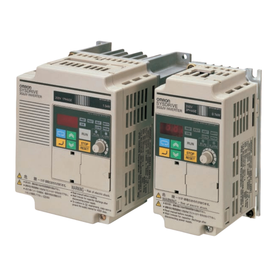
Simple, Compact Inverters
3G3JV
Series
Advertisement
Table of Contents

Related Manuals for Omron 3G3JV


Summary of Contents for Omron 3G3JV
- Page 1 Simple, Compact Inverters 3G3JV Series Note: Do not use this document to operate the Unit. Regional Headquarters OMRON Corporation Authorized Distributor: OMRON EUROPE B.V. FA Systems Division H.Q. Wegalaan 67-69, NL-2132 JD Hoofddorp 66 Matsumoto The Netherlands Mishima-city, Shizuoka 411-8511...
- Page 2 DIN track. The 3G3JV Inverter supports a variety of I/O, such as analog inputs between 0 and 10V, 4 to 20 mA, or 0 to 20 mA, multi- function I/O, and analog monitor outputs. Multi-function inputs The 3G3JV Inverters...
- Page 3 3G3JV Inverter Solutions no mechanical relay contacts, ensuring the safety and opens quickly at a high speed, but closes at a medium-range reliability of the system compared with the ON/OFF control of speed while the system checks the safety of the operation and...
- Page 4 Top protection cover: Remove this cover when wiring the upper terminal block. Upper terminal block: A terminal block on the input side of the main circuit. Digital Operator: Used to set parameters, perform various monitoring, and start and stop the Inverter.
-
Page 5: Digital Operator
Used to reset the Inverter when an error occurs. (See note 3.) Note: 1. The status of the local/remote selection indicator can be only monitored while the Inverter is in operation. Any RUN com- mand input is ignored while this indicator is lit. - Page 6 Other monitor items Note: If the power is turned OFF with the FOUT or IOUT indicator lit, the same indicator will light when the power is turned ON again. In other cases, the FREF indicator will light when the power is turned ON.
- Page 7 U01 will be displayed. Use the Increment or Decrement Key to select the monitor item to be displayed. Press the Enter Key so that the data of the selected monitor item will be displayed. The monitor number display will appear again by pressing the Mode Key.
- Page 8 Using Digital Operator Example of Parameter Settings The following example shows how to set 2 to enable the frequency reference control terminal for 0- to 10-V input in parameter n03 (Frequency Reference Selection). Enable the frequency reference Cancels set control terminal for 0- to 10-V input.
- Page 9 Used to set the inching frequency command. mand Note: 1. With 400-class Inverters, the default settings and maximum values setting ranges for n10, n13, and n15 are double those given in the table. 2. Values longer than 3 digits are rounded up to the next unit multiple.
- Page 10 Inverter automatically for stall prevention during operation. Frequency detection Used to set the frequency to be detected. 0.0 to 400 0.1 Hz level Note: Values longer than 3 digits are rounded up to the next unit multiple.
- Page 11 This parameter is monitored only. Software number Used to display the software number of the Inverter for OMRON’s control reference use. Note This parameter is monitored only. Note: Values longer than 3 digits are rounded up to the next unit multiple.
- Page 12 STOP/RESET Key Function Selection (n06) The n01 through n79 parameters can be displayed and set. When parameter n02 is set to 1, set whether or not to use the Only the error log memory is cleared. STOP/RESET Key of the Digital Operator to stop the Inverter in Enables the initialization of all parameters in 2-wire sequence so that the parameters will return to default values.
- Page 13 Inching frequency com- mand Note: 1. Set the parameters so that the following condition will Note: 1. Values will be set in 0.1-Hz increments if the frequency is less be satisfied. n14 x n12 < n11 x n09 than 100 Hz and 1-Hz increments if the frequency is 100 Hz or over.
- Page 14 This parameter is used to operate the cooling fan of the Inverter Set the upper and lower frequency reference limits in percent- while the Inverter is turned on or only while the Inverter is in op- age based on the maximum frequency as 100%.
- Page 15 Emergency stop Note “STP” is displayed (lit with fault in- Set the frequency of minimum analog input (0 V, 0 mA, or 4 mA) alarm (NC) put ON and flashes with alarm in- in n42 as percentage based on the maximum frequency as put ON) 100%.
- Page 16 Jump Width 0.0 to 25.5 0.1 Hz frequency Note: 1. Values will be set in 0.1-Hz increments if the frequency is less than 100 Hz and 1 Hz-increments if the frequency is 100 Hz or greater. Deceleration time is controlled to prevent 2.
- Page 17 Stall Prevention Level during Acceleration (n56) Overtorque Detection Function Selection (n59 to n61) Set the operation level of a function to stop the acceleration of Set n59 to enable or disable overtorque detection and select the the motor automatically for stall prevention during acceleration.
- Page 18 Select whether to store the frequency reference adjusted with the UP/DOWN function. If n62 is set to 1, the output frequency held by the UP/DOWN function for 5 s or more will be stored in the memory. This value Value Description will be stored in memory even if power is interrupted.
- Page 19 Slip Compensation Functions (n64 to n67) In n64, set the rated slip value of the motor in use. In n65, set the no-load current of the motor in use based on the rated motor current as 100%. In n66, set the gain of the slip compensation function.
-
Page 20: Specifications
Cooling fan Note: 1. The power supply capacity, is the capacity when the Inverter is operating at its rated output. The value will vary with the impedance at the input power supply side. (Because the power factor of the input power supply changes, the power factor will improve if an AC reactor is inserted.) The ratio with the rated current of the motor used and the rated output current of... - Page 21 Ambient temperature –20°C to 60°C Altitude 1,000 m max. Insulation resistance 5 MΩ min. (Do not carry out any insulation resistance or withstand voltage tests) Vibration resistance 9.8 m/s max. between 10 to 20 Hz 2.0 m/s max. between 20 and 50 Hz...
- Page 22 Cooling fan Note: 1. The power supply capacity, is the capacity when the Inverter is operating at its rated output. The value will vary with the impedance at the input power supply side. (Because the power factor of the input power supply changes, the power factor will improve if an AC reactor is inserted.) The ratio with the rated current of the motor used and the rated output current of...
-
Page 23: Terminal Block
3G3JV-A2j: Ground at a resistance of 100 Ω or less. 3G3JV-ABj: Ground at a resistance of 100 Ω or less. 3G3JV-A4j: Ground at a resistance of 10 Ω or less. Connect to a neutral point on the power supply to conform to EC Directives. -
Page 24: Control Circuit Terminals
2. The input method is set to NPN by default, so use the GND common for wiring. An external power supply is not required. When a power supply is used and a common on the plus side is used for wiring, set SW7 to PNP and use a 24-V DC (±10%) - Page 25 Dimensions Dimensions 3G3JV-A2001 to 3G3JV-A2007 (0.1 to 0.75 kW) 3G3JV-A2015 to 3G3JV-A2022 (1.5 to 2.2 kW) 3-phase 200-V AC Input 3-phase 200-V AC Input 3G3JV-AB001 to 3G3JV-AB004 (0.1 to 0.4 kW) 3G3JV-AB007 to 3G3JV-AB015 (0.75 to 1.5 kW) Single-phase 200-V AC Input Single-phase 200-V AC Input 3G3JV-A4002 to 3G3JV-A4022 (0.2 to 2.2 kW)
-
Page 26: Standard Connections
2. The braking resistor cannot be connected because no braking transistor is incorporated. Input Method Selection Switches SW7 and SW8, both of which are located above the control circuit terminals, are used for input method selection. Remove the front cover and optional cover to use these switches. -
Page 27: Protective And Diagnostic Functions
Inverter detects a fault, the fault code will be displayed on the Digital Operator, the fault contact output will operate, and the Inverter output will be shut off causing the motor to coast to a stop. The stopping method can be selected for some faults, and the selected stopping method will be used with these faults. - Page 28 Initial memory fault (F04) → An error in the built-in EEPROM of the Initialize the Inverter with n01 set to 8 or 9 and turn the Inverter off and on. Inverter has been detected. → Replace the Inverter if the same fault occurs again.
- Page 29 The warning detection is a type of Inverter protective function that does not operate the fault contact output and returns the Inverter to its original status once the cause of the error has been removed. The Digital Operator flashes and display the detail of the error. If a warning occurs, take appropriate countermeasures according to the table below.
- Page 30 Inverter will detect this error if n68 → (RS-422A/485 communications Set the termination resistance of only the Inverter located at each end of the network to ON. time-over detection selection) is set to • Noise influence. 0, 1, or 2.
- Page 31 150% of the rated output current of the Inverter. → Check and correct the value. • The frequency reference upper limit set in n30 and the frequency reference lower limit set in n31 do (flashing) not satisfy the following condition.
- Page 32 3G3IV-PUZBABj than that of the Inverter. Eliminates noise in the power line connected to the Inverter and Recommended Option suppresses noise leaking from the Inverter to the power line. There Input Noise Filter are 2 types available: the EMC-conforming Input Noise Filter and the Simple Input Noise Filter.
- Page 33 Fan Unit 3G3IV-PFANj Replacement for the existing cooling fan of the Inverter. Replace the cooling fan if it has reached the end of its service life or a warning of cooling fan failure (FAN) is indicated. Separately Mounted Option Name...
-
Page 34: Fan Unit
3G3IV-PFANj The Fan Unit is a replacement for the presently installed cooling fan of the Inverter. Replace the cooling fan if it has reached the end of its service life or a warning of cooling fan failure (FAN) is indicated. - Page 35 DC Reactor 3G3HV-PUZDABj The DC Reactor suppresses harmonic current generated from the Inverter and improves the power factor of the Inverter. The DC Reactor suppresses harmonic current more effectively than the AC Reactor. Furthermore, the DC Reactor can be used in combination with the AC Reactor.
-
Page 36: Din Track Mounting Bracket
Options DIN Track Mounting Bracket 3G3IV-PEZZ08122j An adapter making it possible to easily mount the Inverter to DIN tracks. Applicable Models Inverter DIN Track Mounting Bracket 3-phase 200 V AC 3G3JV-A2001/-A2002/-A2004/-A2007 3G3IV-PEZZ08122A 3G3JV-A2015/-A2022 3G3IV-PEZZ08122B 3G3JV-A2037 3G3IV-PEZZ08122C Single-phase 200 V AC... -
Page 37: Adapter Panel
Adapter Panel 3G3JV-PSI232Jj An Adapter Panel is required as an interface to connect a Digital Operator (3G3IV-PJVOP140 or 3G3IV-PJVOP146) to the 3G3JV Inverter. There are two models of Adapter Panel available. The 3G3JV-PSI232J is permanently installed and cannot be removed and the 3G3JV-PSI232JC for copying parameters is installed so that it can be removed. - Page 38 Using the Case also enables mounting to a control panel. Note: When a Digital Operator is connected, the Operator on the Inverter cannot be used to control operation (i.e., only display functions will work).
-
Page 39: Digital Operator Case
Digital Operator Case 3G3IV-PEZZ08386A The Digital Operator Case (3G3IV-PEZZ08386A) is used to secure the 3G3IV-PJVOP140 Digital Operator. Without this Case, the Digital Operator’s connection cable cannot be wired. Always use the 3G3IV-PJVOP140 and the Digital Operator Case together. Four, 4.4-dia. mounting holes Four depressions for M4 bolts (Depth: 3.5) -
Page 40: External Dimensions
The AC Reactor suppresses harmonic current generated from the Inverter and improves the power factor of the Inverter. Connect the AC Reactor to the Inverter if the capacity of the power supply is much larger than that of the Inverter. Select the AC Reactor model from the following table according to the motor capacity. -
Page 41: Connection Example
Options EMC-conforming Input Noise Filter 3G3JV-PRSj (Rasmi) The Input Noise Filter is connected between the power supply input terminals (R/L1, S/L2, T/L3) of the Inverter and the power supply in order to meet the EC Directive’s EMC requirements. Connection Example... - Page 42 Options 3G3JV-PRS1020J 3G3JV-PRS3010J Three, Three, 5-dia holes 5-dia holes Four, M4 holes Four, M4 holes (for Inverter mounting use) 3G3JV-PRS3005J 3G3JV-PRS3020J Three, Three, 5-dia holes 5-dia holes Four, M4 holes Four, M4 holes (for Inverter mounting (for Inverter mounting use)
-
Page 43: Simple Input Noise Filter
Options Simple Input Noise Filter The Simple Input Noise Filter is connected to the 3G3EV-PLNFDj (Yaskawa Electric) power input side to eliminate the noise in the power line connected to the Inverter and suppress noise leaking from the Inverter to the power line. -
Page 44: Output Noise Filter
Output Noise Filter 3G3IV-PLFj (Tokin) The Output Noise Filter suppresses the generated noise of the Inverter from being transmitted to the output line. Con- nect the Output Noise Filter to the output side of the Inverter. Connection Example Noise filter... -
Page 45: Inverter Models
0.4 kW 0.75 kW 1.5 kW 2.2 kW 3.7 kW Voltage class 3-phase 200 V AC (200-V class) Single-phase 200 V AC (200-V class) 3-phase 400 V AC (400-V class) Degree of protection Panel-mounting type (IP10 or higher)/closed wall-mounting type... - Page 47 PERFORMANCE DATA Performance data given in this catalog is provided as a guide for the user in determining suitability and does not constitute a warranty. It may represent the result of OMRON’s test conditions, and the users must correlate it to actual application requirements. Actual performance is subject to the OMRON Warranty and Limitations of Liability.
- Page 48 Regional Headquarters OMRON EUROPE B.V. Wegalaan 67-69, NL-2132 JD Hoofddorp The Netherlands Tel: (31)2356-81-300/Fax: (31)2356-81-388 OMRON ELECTRONICS LLC 1 East Commerce Drive, Schaumburg, IL 60173 U.S.A. Tel: (1)847-843-7900/Fax: (1)847-843-8568 OMRON IDM CONTROLS, INC. 9510 N. Houston-Rosslyn Rd. Houston, Texas 77088 Tel: (1)713-849-1900/Fax: (1)713-849-4666 OMRON ASIA PACIFIC PTE.