Dimplex SIK 6TES Installation And Operating Instruction
Brine-to-water heat pump
Hide thumbs
Also See for SIK 6TES:
- Installation and operating instructions manual (56 pages) ,
- Installation and operating instruction (72 pages)
Table of Contents
Advertisement
Available languages
Available languages
Quick Links
SIK 6TES
SIK 8TES
SIK 11TES
SIK 14TES
Montage- und
Gebrauchsanweisung
Sole-Wasser-
Wärmepumpe
für Innenaufstellung
Bestell-Nr. | Order no. | No de commande: 452231.66.34a
Installation and
Operating Instruction
Brine-to-Water
Heat Pump for
Indoor Installation
Glen
Dimplex
Deutschland
Instuctions d'installation
et d'utilisation
Pompe à chaleur
eau glocolée-eau pour
installation intérieure
DE | EN | FR · FD 0201
Dimplex
Advertisement
Chapters
Table of Contents

Related Manuals for Dimplex SIK 6TES


Summary of Contents for Dimplex SIK 6TES
- Page 1 Glen Dimplex Deutschland Dimplex SIK 6TES SIK 8TES SIK 11TES SIK 14TES Montage- und Installation and Instuctions d‘installation Gebrauchsanweisung Operating Instruction et d‘utilisation Sole-Wasser- Brine-to-Water Pompe à chaleur Wärmepumpe Heat Pump for eau glocolée-eau pour für Innenaufstellung Indoor Installation installation intérieure Bestell-Nr.
-
Page 3: Table Of Contents
SIK 6TES - SIK 14TES Deutsch Inhaltsverzeichnis Sicherheitshinweise............................DE-2 1.1 Symbole und Kennzeichnung............................DE-2 1.2 Bestimmungsgemäßer Gebrauch ..........................DE-2 1.3 Gesetzliche Vorschriften und Richtlinien.........................DE-2 1.4 Energiesparende Handhabung der Wärmepumpe ....................DE-2 Verwendungszweck der Wärmepumpe ....................DE-3 2.1 Anwendungsbereich...............................DE-3 2.2 Arbeitsweise..................................DE-3 Grundgerät..............................DE-3 Zubehör .................................DE-4 4.1 Soleverteiler ..................................DE-4 4.2 Solepressostat...................................DE-4... -
Page 4: Sicherheitshinweise
Deutsch SIK 6TES - SIK 14TES ACHTUNG! Sicherheitshinweise Für den Betrieb und die Wartung einer Wärmepumpe sind die rechtlichen Anforderungen des Landes einzuhalten, in dem 1.1 Symbole und Kennzeichnung Wärmepumpe betrieben wird. nach Kältemittelfüllmenge ist die Dichtheit der Wärmepumpe in Besonders wichtige Hinweise sind in dieser Anleitung mit regelmäßigen Abständen durch entsprechend geschultes... -
Page 5: Verwendungszweck Der Wärmepumpe
SIK 6TES - SIK 14TES Deutsch Verwendungszweck der Grundgerät Wärmepumpe Das Grundgerät besteht aus einer anschlussfertigen Wärme- pumpe für Innenaufstellung in Kompaktbauweise. Zusätzlich zum Schaltblech mit integriertem Wärmepumpenmanager ent- 2.1 Anwendungsbereich hält das Gerät bereits wichtige Baugruppen des Heiz- und Sole- kreises: Die Sole/Wasser-Wärmepumpe ist ausschließlich für die Erwär-... -
Page 6: Zubehör
Deutsch SIK 6TES - SIK 14TES Zubehör Transport Zum Transport auf ebenem Untergrund eignet sich ein Hubwa- 4.1 Soleverteiler gen. Muss die Wärmepumpe auf unebenem Untergrund oder über Treppen befördert werden, kann dies mit Tragriemen ge- Der Soleverteiler vereinigt die Kollektorschleifen der Wärme- schehen. -
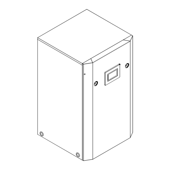
Page 7: Aufstellung
SIK 6TES - SIK 14TES Deutsch 7.2 Heizungsseitiger Anschluss Aufstellung Die Wärmepumpe ist mit getrennten Ausgängen für Heiz- und 6.1 Allgemeine Hinweise Warmwasserkreis ausgerüstet. Ist keine Warmwassererwärmung durch die Wärmepumpe vor- Die Sole/Wasser Wärmepumpe muss in einem frostfreien und gesehen, so ist der Warmwasserausgang dauerhaft abzudich- trockenen Raum auf einer ebenen, glatten und waagerechten ten. -
Page 8: Wärmequellenseitiger Anschluss
Deutsch SIK 6TES - SIK 14TES 7.3 Wärmequellenseitiger Mindestheizwasserdurchsatz Der Mindestheizwasserdurchsatz der Wärmepumpe ist in Anschluss jedem Betriebszustand der Heizungsanlage sicherzustellen. Dieses kann z.B. durch Installation eines doppelt differenz- Folgende Vorgehensweise ist beim Anschluss einzuhalten: drucklosen Verteilers oder eines Überströmventils erreicht wer- Die Soleleitung am Vor- und Rücklauf der Wärmepumpe an-... - Page 9 SIK 6TES - SIK 14TES Deutsch 7.4.1 Fühlerkennlinien Auslegungsparameter Fühlerleitung Leitermaterial Temperatur in °C Kabellänge 50 m NTC-2 in k 14,6 11,4 Umgebungstemperatur 35 °C NTC-10 in k 67,7 53,4 42,3 33,9 27,3 22,1 18,0 B2 (DIN VDE 0298-4 /...
-
Page 10: Elektrischer Anschluss
Deutsch SIK 6TES - SIK 14TES 7.5 Elektrischer Anschluss Das Schütz (K20) für den Tauchheizkörper (E10) ist bei mo- noenergetischen Anlagen (2.WE) entsprechend der Heiz- körperleistung auszulegen und bauseits beizustellen. Die 7.5.1 Allgemein Ansteuerung (230 V AC) erfolgt aus dem Wärmepumpen- manager über die Klemmen X2/N und N1-J13/NO4... -
Page 11: Inbetriebnahme
SIK 6TES - SIK 14TES Deutsch 8.3 Vorgehensweise bei Inbetriebnahme Inbetriebnahme 8.1 Allgemein Die Inbetriebnahme der Wärmepumpe erfolgt über den Wärmepumpenmanager. Um eine ordnungsgemäße Inbetriebnahme zu gewährleisten, sollte diese von einem vom Werk autorisierten Kundendienst ACHTUNG! durchgeführt werden. Unter bestimmten Bedingungen ist Die Inbetriebnahme der Wärmepumpe muss gemäß... -
Page 12: Pflege / Reinigung
Deutsch SIK 6TES - SIK 14TES Pflege / Reinigung 10 Störungen / Fehlersuche Diese Wärmepumpe ist ein Qualitätsprodukt und sollte stö- 9.1 Pflege rungsfrei arbeiten. Tritt dennoch eine Störung auf, wird dies im Display des Wärmepumpenmanagers angezeigt. Schlagen Sie Um Betriebsstörungen durch Schmutzablagerungen in den dazu auf der Seite Störungen und Fehlersuche in der Ge-... -
Page 13: Geräteinformation
SIK 6TES - SIK 14TES Deutsch 12 Geräteinformation Typ- und Verkaufsbezeichnung SIK 6TES SIK 8TES SIK 11TES SIK 14TES Bauform Wärmequelle Sole Sole Sole Sole Ausführung Kompakt Kompakt Kompakt Kompakt Regler integriert integriert integriert integriert Wärmemengenzähler integriert integriert integriert integriert... - Page 14 Deutsch SIK 6TES - SIK 14TES Nennstrom B0 / W35 / cos A / -- 2,3 / 0,8 2,9 / 0,8 3,8 / 0,8 5,0 / 0,8 Leistungsaufnahme Verdichterschutz (pro Verdichter) Leistungsaufnahme Heizungsumwälzpumpe max. 70 max. 70 max. 70 max.
-
Page 15: Produktinformationen Gemäß Verordnung (Eu) Nr.813/2013, Anhang Ii, Tabelle 2
Kontakt Glen Dimplex Deutschland GmbH, Am Goldenen Feld 18, 95326 Kulmbach (*) Für Heizgeräte und Kombiheizgeräte mit Wärmepumpe ist die Wärmenennleistung Prated gleich der Auslegungslast im Heizbetrieb Pdesingh und die Wärmenennleistung eines Zusatzheizgerätes Psup gleich der zusaätzlichen Heizleistung sup(Tj ). - Page 16 Kontakt Glen Dimplex Deutschland GmbH, Am Goldenen Feld 18, 95326 Kulmbach (*) Für Heizgeräte und Kombiheizgeräte mit Wärmepumpe ist die Wärmenennleistung Prated gleich der Auslegungslast im Heizbetrieb Pdesingh und die Wärmenennleistung eines Zusatzheizgerätes Psup gleich der zusaätzlichen Heizleistung sup(Tj ).
- Page 17 Kontakt Glen Dimplex Deutschland GmbH, Am Goldenen Feld 18, 95326 Kulmbach (*) Für Heizgeräte und Kombiheizgeräte mit Wärmepumpe ist die Wärmenennleistung Prated gleich der Auslegungslast im Heizbetrieb Pdesingh und die Wärmenennleistung eines Zusatzheizgerätes Psup gleich der zusaätzlichen Heizleistung sup(Tj ).
- Page 18 Kontakt Glen Dimplex Deutschland GmbH, Am Goldenen Feld 18, 95326 Kulmbach (*) Für Heizgeräte und Kombiheizgeräte mit Wärmepumpe ist die Wärmenennleistung Prated gleich der Auslegungslast im Heizbetrieb Pdesingh und die Wärmenennleistung eines Zusatzheizgerätes Psup gleich der zusaätzlichen Heizleistung sup(Tj ).
-
Page 19: Garantieurkunde
SIK 6TES - SIK 14TES Deutsch Eine Verlängerung der Garantie auf 60 Monate oder mehr für Hei- 14 Garantieurkunde zungs-Wärmepumpen und zentrale Wohnungslüftungsgeräte ab der ersten Inbetriebsetzung, spätestens jedoch 6 Monate nach Glen Dimplex Deutschland Kaufdatum, wird gemäß den nachfolgenden Bedingungen gewährt (Heizungs-Wärmepumpen, Zentrale Wohnungslüftungsgeräte) - Page 20 Deutsch SIK 6TES - SIK 14TES DE-18 452231.66.34a · FD 0201 www.glendimplex.de...
- Page 21 SIK 6TES - SIK 14TES English Table of contents Safety notes..............................EN-2 1.1 Symbols and markings ..............................EN-2 1.2 Intended Use ..................................EN-2 1.3 Legal Regulations and Directives ..........................EN-2 1.4 Energy-Efficient Use of the Heat Pump ........................EN-2 Purpose of the Heat Pump........................EN-3 2.1 Application ..................................EN-3 2.2 Operating Principle................................EN-3...
-
Page 22: Safety Notes
English SIK 6TES - SIK 14TES 1.4 Energy-Efficient Use of the Heat Safety notes Pump 1.1 Symbols and markings By operating this heat pump you are helping to protect our en- vironment. Both the heating system and the heat source must... -
Page 23: Purpose Of The Heat Pump
SIK 6TES - SIK 14TES English Purpose of the Heat Pump Basic Device The basic device consists of a ready-to-use heat pump for in- 2.1 Application door installation in a compact design. In addition to the control panel with integral heat pump manager, the device is already... -
Page 24: Accessories
English SIK 6TES - SIK 14TES Accessories Transport A lift truck is suited for transporting the unit on a level surface. 4.1 Brine Circuit Manifold Carrying straps may be used if the heat pump needs to be transported on an uneven surface or carried up or down stairs. -
Page 25: Set-Up
SIK 6TES - SIK 14TES English 7.2 Heating System Connection Set-up The heat pump is equipped with separate outputs for the heat- 6.1 General Information ing circuit and the hot water circuit. If the heat pump is not intended to be used to heat up the hot The brine-to-water heat pump must be installed in a frost-free, water, the hot water output must be permanently sealed. -
Page 26: Heat Source Connection
English SIK 6TES - SIK 14TES 7.3 Heat Source Connection Minimum heating water flow rate The minimum heating water flow rate through the heat pump The following procedure must be observed when connecting must be assured in all operating states of the heating system. - Page 27 SIK 6TES - SIK 14TES English 7.4.1 Sensor characteristic curves Dimensioning parameter sensor lead Conductor material Temperature in °C Cable-length 50 m NTC-2 in k 14.6 11.4 Ambient temperature 35 °C NTC-10 in k 67.7 53.4 42.3 33.9 27.3 22.1 18.0...
-
Page 28: Electrical Connection
English SIK 6TES - SIK 14TES 7.5 Electrical connection The contactor (K20) for the immersion heater (E10) of mono energy systems (HG2) should be dimensioned ac- cording to the radiator output and must be supplied by the 7.5.1 General customer. It is controlled (230 V AC) by the heat pump manager via terminals X2/N and N1-J13/NO4. -
Page 29: Start-Up
SIK 6TES - SIK 14TES English 8.3 Start-up Procedure Start-up The heat pump is started up via the heat pump manager. 8.1 General Information CAUTION! To ensure that start-up is performed correctly, it should only be The heat pump must be started up in accordance with the... -
Page 30: Maintenance And Cleaning
English SIK 6TES - SIK 14TES Maintenance and Cleaning 10 Faults / Trouble-Shooting This heat pump is a quality product and is designed for trouble- 9.1 Maintenance free operation. In the event that a fault should occur, it will be indicated on the heat pump manager display. -
Page 31: Device Information
SIK 6TES - SIK 14TES English 12 Device Information Type and order code SIK 6TES SIK 8TES SIK 11TES SIK 14TES Design Heat source Brine Brine Brine Brine Model Compact Compact Compact Compact Contr. Integrated Integrated Integrated Integrated Thermal energy meter... - Page 32 English SIK 6TES - SIK 14TES 1.24 / 2.7 1.61 / 3.3 2.13 / 4.5 2.78 / 5.5 Nominal power consumption B0 / W35 / max. power consumption Nominal current at B0 / W35 / cos A / -- 2.3 / 0.8...
-
Page 33: Product Information As Per Regulation (Eu) No 813/2013, Annex Ii, Table 2
Contact details Glen Dimplex Deutschland GmbH, Am Goldenen Feld 18, 95326 Kulmbach (*) For heat pump space heaters and heat pump combination heaters, the rated output Prated is equal to the design load for heating Pdesignh , and the rated heat output of a supplementary capacity for heating sup(Tj ). - Page 34 Contact details Glen Dimplex Deutschland GmbH, Am Goldenen Feld 18, 95326 Kulmbach (*) For heat pump space heaters and heat pump combination heaters, the rated output Prated is equal to the design load for heating Pdesignh , and the rated heat output of a supplementary capacity for heating sup(Tj ).
- Page 35 Contact details Glen Dimplex Deutschland GmbH, Am Goldenen Feld 18, 95326 Kulmbach (*) For heat pump space heaters and heat pump combination heaters, the rated output Prated is equal to the design load for heating Pdesignh , and the rated heat output of a supplementary capacity for heating sup(Tj ).
- Page 36 Contact details Glen Dimplex Deutschland GmbH, Am Goldenen Feld 18, 95326 Kulmbach (*) For heat pump space heaters and heat pump combination heaters, the rated output Prated is equal to the design load for heating Pdesignh , and the rated heat output of a supplementary capacity for heating sup(Tj ).
- Page 37 SIK 6TES - SIK 14TES Français Table des matières Consignes de sécurité..........................FR-2 1.1 Symboles et identification ............................FR-2 1.2 Utilisation conforme................................ FR-2 1.3 Dispositions légales et directives..........................FR-2 1.4 Utilisation de la pompe à chaleur pour économiser de l'énergie..............FR-2 Utilisation de la pompe à...
-
Page 38: Consignes De Sécurité
Français SIK 6TES - SIK 14TES Vous trouverez plus d'informations à ce sujet dans le journal de Consignes de sécurité bord ci-joint. 1.1 Symboles et identification 1.4 Utilisation de la pompe à chaleur pour économiser de Les indications importantes dans ces instructions sont signa- lées par ATTENTION ! et REMARQUE. -
Page 39: Utilisation De La Pompe À Chaleur
SIK 6TES - SIK 14TES Français Utilisation de la pompe à Appareil de base chaleur Il s’agit d’une pompe à chaleur pour installation intérieure, prête à brancher, sous forme compacte. En plus du panneau de com- mande avec gestionnaire de pompe à chaleur intégrée, l’appa- 2.1 Domaine d’utilisation... -
Page 40: Accessoires
Français SIK 6TES - SIK 14TES Accessoires Transport Le transport par chariot élévateur convient bien à un déplace- 4.1 Distributeur d'eau glycolée ment sur surface plane. Si la pompe à chaleur doit être convoyée sur une surface non plane ou dans des escaliers, il est Le distributeur d’eau glycolée réunit les boucles du collecteur... -
Page 41: Installation
SIK 6TES - SIK 14TES Français 7.2 Branchement côté installation Installation de chauffage 6.1 Généralités La pompe à chaleur est équipée de sorties séparées pour les circuits d’eau chaude et de chauffage. La pompe à chaleur eau glycolée/eau doit être installée dans un local sec à... -
Page 42: Raccordement Côté Source De Chaleur
Français SIK 6TES - SIK 14TES 7.3 Raccordement côté source de ATTENTION ! Il faut veiller, dans le cas d'eau entièrement déminéralisée, à chaleur ce que le seuil inférieur admis pour la valeur pH minimale de 7,5 (valeur minimale admise pour le cuivre) ne soit pas Pour le raccordement, il faut procéder exactement comme indi-... - Page 43 SIK 6TES - SIK 14TES Français 7.4.1 Courbes caractéristiques de la sonde Paramètre de dimensionnement câble de sonde Matériau conducteur Température en °C Longueur de câble 50 m NTC-2 en k 14,6 11,4 Température ambiante 35 °C NTC-10 en k...
-
Page 44: Branchements Électriques
Français SIK 6TES - SIK 14TES 7.5 Branchements électriques Le contacteur de blocage de la société d’électricité (K22) avec contacts principaux et un contact auxiliaire doit être dimensionné en fonction de la puissance de la pompe à 7.5.1 Généralités chaleur et fourni par le client. -
Page 45: Mise En Service
SIK 6TES - SIK 14TES Français 8.3 Procédures à suivre à la mise en Mise en service service 8.1 Remarques d’ordre général La mise en service de la pompe à chaleur s’effectue via le régu- lateur de pompe à chaleur. -
Page 46: Entretien / Nettoyage
Français SIK 6TES - SIK 14TES 9.3 Nettoyage côté source de Entretien / nettoyage chaleur 9.1 Entretien ATTENTION ! Pour éviter des dysfonctionnements dus à des dépôts dans les Monter, sur la pompe à chaleur, le filtre qui vous est livré dans échangeurs thermiques de la pompe à... -
Page 47: Informations Sur Les Appareils
SIK 6TES - SIK 14TES Français 12 Informations sur les appareils Désignation technique et référence de commande SIK 6TES SIK 8TES SIK 11TES SIK 14TES Design Source de chaleur Eau glycolée Eau glycolée Eau glycolée Eau glycolée Version Compacte Compacte... - Page 48 Français SIK 6TES - SIK 14TES Courant nominal B0 / W35 / cos A / -- 2,3 / 0,8 2,9 / 0,8 3,8 / 0,8 5,0 / 0,8 Puissance absorbée protection compresseur (par compresseur)W Consommation de puissance circulateur du circuit de chauffageW max.
-
Page 49: Informations Sur Le
Glen Dimplex Deutschland GmbH, Am Goldenen Feld 18, 95326 Kulmbach Coordonnées de contact (*) Pour les dispositifs de chauffage des locaux par pompe à chaleur et les dispositifs de chauffage mixtes par pompe à chaleur, la puissance thermique nominale Prated est égale à... - Page 50 Glen Dimplex Deutschland GmbH, Am Goldenen Feld 18, 95326 Kulmbach Coordonnées de contact (*) Pour les dispositifs de chauffage des locaux par pompe à chaleur et les dispositifs de chauffage mixtes par pompe à chaleur, la puissance thermique nominale Prated est égale à...
- Page 51 Glen Dimplex Deutschland GmbH, Am Goldenen Feld 18, 95326 Kulmbach Coordonnées de contact (*) Pour les dispositifs de chauffage des locaux par pompe à chaleur et les dispositifs de chauffage mixtes par pompe à chaleur, la puissance thermique nominale Prated est égale à...
- Page 52 Glen Dimplex Deutschland GmbH, Am Goldenen Feld 18, 95326 Kulmbach Coordonnées de contact (*) Pour les dispositifs de chauffage des locaux par pompe à chaleur et les dispositifs de chauffage mixtes par pompe à chaleur, la puissance thermique nominale Prated est égale à...
-
Page 53: Anhang / Appendix / Annexes
Maßbild / Dimension Drawing / Schéma coté ..................A-II Diagramme / Diagrams / Diagrammes ....................A-III 2.1 Kennlinien / Characteristic Curves / Courbes caractéristiques SIK 6TES............A-III 2.2 Kennlinien / Characteristic Curves / Courbes caractéristiques SIK 8TES............. A-IV 2.3 Kennlinien / Characteristic Curves / Courbes caractéristiques SIK 11TES ............A-V 2.4 Kennlinien / Characteristic Curves / Courbes caractéristiques SIK 14TES .......... -
Page 54: Maßbild / Dimension Drawing / Schéma Coté
Anhang · Appendix · Annexes SIK 6TES - SIK 14TES 1 Maßbild / Dimension Drawing / Schéma coté A-II 452231.66.34a · FD 0201 www.glendimplex.de... -
Page 55: Diagramme / Diagrams / Diagrammes
SIK 6TES - SIK 14TES Anhang · Appendix · Annexes 2 Diagramme / Diagrams / Diagrammes 2.1 Kennlinien / Characteristic Curves / Courbes caractéristiques SIK 6TES Heizleistung in [kW] Wasseraustrittstemperatur in [°C] Heating capacity in [kW] Water outlet temperature in [°C] Puissance de chauffage en [kW] Température de sortie de l'eau en [°C]... - Page 56 Anhang · Appendix · Annexes SIK 6TES - SIK 14TES 2.2 Kennlinien / Characteristic Curves / Courbes caractéristiques SIK 8TES Heizleistung in [kW] Wasseraustrittstemperatur in [°C] Heating capacity in [kW] Water outlet temperature in [°C] Puissance de chauffage en [kW] Température de sortie de l'eau en [°C]...
- Page 57 SIK 6TES - SIK 14TES Anhang · Appendix · Annexes 2.3 Kennlinien / Characteristic Curves / Courbes caractéristiques SIK 11TES Wasseraustrittstemperatur in [°C] Heizleistung in [kW] Water outlet temperature in [°C] Heating capacity in [kW] Température de sortie de l'eau en [°C]...
- Page 58 Anhang · Appendix · Annexes SIK 6TES - SIK 14TES 2.4 Kennlinien / Characteristic Curves / Courbes caractéristiques SIK 14TES Heizleistung in [kW] Wasseraustrittstemperatur in [°C] Water outlet temperature in [°C] Heating capacity in [kW] Température de sortie de l'eau en [°C]...
- Page 59 SIK 6TES - SIK 14TES Anhang · Appendix · Annexes 2.5 Einsatzgrenzendiagramm / Operating limits diagram / Diagramme des seuils d'utilisation Wasseraustritt (+/- 2 K) Water outlet (+/- 2 K) Sortie d'eau (+/- 2 K) Wärmequelleneintrittstemperatur [°C] Heat source inlet temperature [°C] Température d'entrée de la source de chaleur [°C]...
-
Page 60: Stromlaufpläne / Circuit Diagrams / Schémas Électriques
Anhang · Appendix · Annexes SIK 6TES - SIK 14TES 3 Stromlaufpläne / Circuit Diagrams / Schémas électriques 3.1 Steuerung / Control / Commande A-VIII 452231.66.34a · FD 0201 www.glendimplex.de... - Page 61 SIK 6TES - SIK 14TES Anhang · Appendix · Annexes 3.2 Steuerung / Control / Commande www.glendimplex.de 452231.66.34a · FD 0201 A-IX...
- Page 62 Anhang · Appendix · Annexes SIK 6TES - SIK 14TES 3.3 Last / Load / Charge 452231.66.34a · FD 0201 www.glendimplex.de...
- Page 63 SIK 6TES - SIK 14TES Anhang · Appendix · Annexes 3.4 Anschlussplan / Circuit Diagram / Schéma électrique www.glendimplex.de 452231.66.34a · FD 0201 A-XI...
- Page 64 Anhang · Appendix · Annexes SIK 6TES - SIK 14TES 3.5 Anschlussplan / Circuit Diagram / Schéma électrique A-XII 452231.66.34a · FD 0201 www.glendimplex.de...
- Page 65 SIK 6TES - SIK 14TES Anhang · Appendix · Annexes 3.6 Legende / Legend / Légende Brücke EVU-Sperre, muss eingelegt werden, wenn Utility block (EVU) bridge must be inserted if no Pont de blocage de la société d'électricité, à kein EVU-Sperrschütz vorhanden ist utility blocking contactor is present insérer en absence de contacteur de blocage de la...
- Page 66 Anhang · Appendix · Annexes SIK 6TES - SIK 14TES Sicherheitstrenntransformator 230/24V AC- Safety isolating transformer 230/24 V AC-Regula- Transformateur sectionneur de sécurité 230/24 V Regelung tion Régulatio Klemmleiste Einspeisung Last Terminal strip, infeed Alimentation bornier Klemmleiste Spannung = 230V AC Schaltkasten Terminal strip voltage = 230 V AC Switch box Tension bornier = 230 V AC Boîtier électrique...
-
Page 67: Hydraulisches Einbindungsschema / Hydraulic Integration Diagram / Schéma D'intégration Hydraulique
SIK 6TES - SIK 14TES Anhang · Appendix · Annexes 4 Hydraulisches Einbindungsschema / Hydraulic integration Diagram / Schéma d’intégration hydraulique 4.1 Darstellung / Schematic View / Représentation www.glendimplex.de 452231.66.34a · FD 0201 A-XV... - Page 68 Anhang · Appendix · Annexes SIK 6TES - SIK 14TES 4.2 Legende / Legend / Légende Rückschlagventil Check valve Clapet anti-retour Absperrventil Shutoff valve Robinet d’arrêt Überstromventil Overflow valve Soupape différentielle Sicherheitsventilkombination Safety valve combination Groupe de valves de sécurité...
-
Page 69: Konformitätserklärung / Declaration Of Conformity / Déclaration De Conformité
SIK 6TES - SIK 14TES Anhang · Appendix · Annexes 5 Konformitätserklärung / Declaration of Conformity / Déclaration de conformité Die aktuelle CE-Konformitätserklärung finden sie als Download unter: You can find and download the current CE conformity declaration at: Vous pouvez télécharger la déclaration de conformité CE actuelle sous : https://glendimplex.de/sik6tes... - Page 70 Anhang · Appendix · Annexes SIK 6TES - SIK 14TES A-XVIII 452231.66.34a · FD 0201 www.glendimplex.de...
- Page 71 SIK 6TES - SIK 14TES Anhang · Appendix · Annexes www.glendimplex.de 452231.66.34a · FD 0201 A-XIX...
- Page 72 Glen Dimplex Deutschland Verkauf und Planung Service und Technischer Support Zentrale Projektierung Kundendienst, Technische Unter- stützung und Ersatzteile Glen Dimplex Deutschland GmbH Projektierung Ihrer Projekte und Hilfestellung vor und nach Installation Am Goldenen Feld 18 Planungsunterstützung. Ihrer Geräte D-95326 Kulmbach...
- Page 73 Glen Dimplex Deutschland Dimplex SIK 6TES SIK 8TES SIK 11TES SIK 14TES Instruzioni d‘uso e montaggio Pompa di calore geotermica/acqua per intallazione interna N. d’ordinazione : 452231.69.09-IT IT · FD 0201...
- Page 75 SIK 6TES - SIK 14TES Italiano Sommario Note di sicurezza ............................IT-2 1.1 Simboli e contrassegno..............................IT-2 1.2 Uso conforme..................................IT-2 1.3 Norme e disposizioni di legge............................IT-2 1.4 Risparmio energetico nell'utilizzo della pompa di calore ..................IT-2 Uso previsto della pompa di calore ......................IT-3 2.1 Campo di applicazione..............................IT-3...
-
Page 76: Note Di Sicurezza
Italiano SIK 6TES - SIK 14TES 1.4 Risparmio energetico Note di sicurezza nell'utilizzo della pompa di 1.1 Simboli e contrassegno calore All'interno del manuale, le avvertenze particolarmente impor- Con l'utilizzo di questa pompa di calore si contribuisce al ri- tanti sono accompagnate dalle diciture ATTENZIONE! e NOTA. -
Page 77: Uso Previsto Della Pompa Di Calore
SIK 6TES - SIK 14TES Italiano Uso previsto della pompa di Unità principale calore L'unità principale è composta da una pompa di calore da instal- lazione interna in formato compatto, pronta per l'allacciamento. Oltre alla piastra interruttori con programmatore della pompa di 2.1 Campo di applicazione... -
Page 78: Accessori
Italiano SIK 6TES - SIK 14TES Accessori Trasporto Per il trasporto su superficie piana utilizzare un carrello eleva- 4.1 Collettore geotermico tore. Se la pompa di calore deve essere trasportata su superficie accidentata o su scale, è possibile utilizzare delle cinghie di tra- Il collettore geotermico unisce la rete del collettore dell'im- sporto. -
Page 79: Installazione
SIK 6TES - SIK 14TES Italiano Sensore di temperatura Installazione 7.2 Allacciamento lato 6.1 Note generali riscaldamento La pompa di calore geotermica/acqua deve essere installata in La pompa di calore è munita di uscite separate per i circuiti un ambiente asciutto e senza rischio di gelo su una superficie dell'acqua di riscaldamento e dell'acqua calda sanitaria. -
Page 80: Allacciamento Lato Fonte Di Calore
Italiano SIK 6TES - SIK 14TES 7.3 Allacciamento lato fonte di Portata minima d'acqua di riscaldamento La portata minima d'acqua di riscaldamento della pompa di ca- calore lore deve essere garantita in ogni stato d'esercizio dell'impianto di riscaldamento. Tale condizione può essere raggiunta, ad... - Page 81 SIK 6TES - SIK 14TES Italiano 7.4.1 Curve caratteristiche delle sonde Parametri di progetto cavo Materiale conduttore Temperatura in °C Lunghezza cavo 50 m NTC-2 in k 14,6 11,4 Temperatura ambiente 35 °C NTC-10 in k 67,7 53,4 42,3 33,9...
-
Page 82: Allacciamento Elettrico
Italiano SIK 6TES - SIK 14TES 7.5 Allacciamento elettrico Il contattore di blocco dell'azienda distributrice dell'energia elettrica (K22) con contatti principali e un contatto ausilia- rio deve essere commisurato alla potenza della pompa di 7.5.1 Informazioni generali calore e messo a disposizione a carico del committente. -
Page 83: Avviamento
SIK 6TES - SIK 14TES Italiano 8.3 Procedura di avviamento Avviamento L'avviamento della pompa di calore avviene mediante il pro- 8.1 Informazioni generali grammatore della pompa di calore. ATTENZIONE! Per assicurare un corretto avviamento, esso deve essere ese- guito da un servizio clienti autorizzato dal costruttore. In deter- L'avviamento della pompa di calore deve avvenire attenendosi minate condizioni, tale operazione è... -
Page 84: Manutenzione/Pulizia
Italiano SIK 6TES - SIK 14TES Manutenzione/Pulizia 10 Blocchi / Localizzazione errori 9.1 Manutenzione La pompa di calore è un prodotto di qualità il cui funzionamento Per evitare anomalie di funzionamento a causa di depositi di im- è esente da blocchi. Qualora tuttavia dovesse verificarsi un purità... -
Page 85: Informazioni Sull'apparecchio
SIK 6TES - SIK 14TES Italiano 12 Informazioni sull'apparecchio Modello e denominazione commerciale SIK 6TES SIK 8TES SIK 11TES SIK 14TES Tipo di costruzione Acqua gli- Fonte di calore Acqua glicolata Acqua glicolata Acqua glicolata colata Modello Compatto Compatto Compatto... - Page 86 Italiano SIK 6TES - SIK 14TES 28 (senza Softstar- Corrente di avviamento con Softstarter ter) 1,24 / 2,7 1,61 / 3,3 2,13 / 4,5 2,78 / 5,5 Potenza nominale B0/W35/assorbimento max. Corrente nominale B0/W35/cos A / -- 2,3 / 0,8...
-
Page 87: Informazioni Sul Prodotto In Conformità Al Regolamento (Ue) N. 813/2013, Allegato Ii, Tabella 2
Recapiti Glen Dimplex Deutschland GmbH, Am Goldenen Feld 18, 95326 Kulmbach (*) Per gli apparecchi a pompa di calore per il riscaldamento d’ambiente e gli apparecchi di riscaldamento misti a pompa di calore, la potenza termica nominale Pnominale è pari al carico teorico per il riscaldamento Pdesignh e la potenza termica nominale di un riscaldatore supplementare Psup è pari alla capacità... - Page 88 Recapiti Glen Dimplex Deutschland GmbH, Am Goldenen Feld 18, 95326 Kulmbach (*) Per gli apparecchi a pompa di calore per il riscaldamento d’ambiente e gli apparecchi di riscaldamento misti a pompa di calore, la potenza termica nominale Pnominale è pari al carico teorico per il riscaldamento Pdesignh e la potenza termica nominale di un riscaldatore supplementare Psup è pari alla capacità...
- Page 89 Recapiti Glen Dimplex Deutschland GmbH, Am Goldenen Feld 18, 95326 Kulmbach (*) Per gli apparecchi a pompa di calore per il riscaldamento d’ambiente e gli apparecchi di riscaldamento misti a pompa di calore, la potenza termica nominale Pnominale è pari al carico teorico per il riscaldamento Pdesignh e la potenza termica nominale di un riscaldatore supplementare Psup è pari alla capacità...
- Page 90 Recapiti Glen Dimplex Deutschland GmbH, Am Goldenen Feld 18, 95326 Kulmbach (*) Per gli apparecchi a pompa di calore per il riscaldamento d’ambiente e gli apparecchi di riscaldamento misti a pompa di calore, la potenza termica nominale Pnominale è pari al carico teorico per il riscaldamento Pdesignh e la potenza termica nominale di un riscaldatore supplementare Psup è pari alla capacità...
-
Page 91: Appendice
SIK 6TES - SIK 14TES Appendice Appendice Disegno quotato ............................A-II Diagrammi..............................A-III 2.1 Curve caratteristiche SIK 6TES............................A-III 2.2 Curve caratteristiche SIK 8TES............................. A-IV 2.3 Curve caratteristiche SIK 11TES............................A-V 2.4 Curve caratteristiche SIK 14TES..........................A-VI 2.5 Diagramma limiti operativi ............................A-VII Schemi elettrici............................ -
Page 92: Disegno Quotato
Appendice SIK 6TES - SIK 14TES 1 Disegno quotato A-II 452231.69.09-IT · FD 0201 www.glendimplex.de... -
Page 93: Diagrammi
SIK 6TES - SIK 14TES Appendice 2 Diagrammi 2.1 Curve caratteristiche SIK 6TES Heizleistung in [kW] Wasseraustrittstemperatur in [°C] Potenza termica in [kW] Temperatura erogazione acqua calda sanitaria in [°C] Puissance de chauffage en [kW] Température de sortie de l'eau en [°C]... -
Page 94: Curve Caratteristiche Sik 8Tes
Appendice SIK 6TES - SIK 14TES 2.2 Curve caratteristiche SIK 8TES Wasseraustrittstemperatur in [°C] Heizleistung in [kW] Temperatura erogazione acqua calda sanitaria in [°C] Potenza termica in [kW] Température de sortie de l'eau en [°C] Puissance de chauffage en [kW]... -
Page 95: Curve Caratteristiche Sik 11Tes
SIK 6TES - SIK 14TES Appendice 2.3 Curve caratteristiche SIK 11TES Heizleistung in [kW] Wasseraustrittstemperatur in [°C] Temperatura erogazione acqua calda sanitaria in [°C] Potenza termica in [kW] Température de sortie de l'eau en [°C] Puissance de chauffage en [kW]... -
Page 96: Curve Caratteristiche Sik 14Tes
Appendice SIK 6TES - SIK 14TES 2.4 Curve caratteristiche SIK 14TES Wasseraustrittstemperatur in [°C] Heizleistung in [kW] Temperatura erogazione acqua calda sanitaria in [°C] Potenza termica in [kW] Température de sortie de l'eau en [°C] Puissance de chauffage en [kW]... -
Page 97: Diagramma Limiti Operativi
SIK 6TES - SIK 14TES Appendice 2.5 Diagramma limiti operativi Wasseraustritt (+/- 2 K) Uscita dell'acqua (+/- 2 K) Sortie d'eau (+/- 2 K) Wärmequelleneintrittstemperatur [°C] Temperatura di ingresso della fonte di calore [°C] Température d'entrée de la source de chaleur [°C] www.glendimplex.de... -
Page 98: Schemi Elettrici
Appendice SIK 6TES - SIK 14TES 3 Schemi elettrici 3.1 Comando A-VIII 452231.69.09-IT · FD 0201 www.glendimplex.de... - Page 99 SIK 6TES - SIK 14TES Appendice 3.2 Comando www.glendimplex.de 452231.69.09-IT · FD 0201 A-IX...
-
Page 100: Carico
Appendice SIK 6TES - SIK 14TES 3.3 Carico 452231.69.09-IT · FD 0201 www.glendimplex.de... -
Page 101: Schema Di Collegamento
SIK 6TES - SIK 14TES Appendice 3.4 Schema di collegamento www.glendimplex.de 452231.69.09-IT · FD 0201 A-XI... - Page 102 Appendice SIK 6TES - SIK 14TES 3.5 Schema di collegamento A-XII 452231.69.09-IT · FD 0201 www.glendimplex.de...
-
Page 103: Legenda
SIK 6TES - SIK 14TES Appendice 3.6 Legenda Brücke EVU-Sperre, muss eingelegt werden, Ponte stacco della corrente dall'azienda elettrica, Pont de blocage de la société d'électricité, à wenn kein EVU-Sperrschütz vorhanden ist da inserire in mancanza di un contattore di blocco insérer en absence de contacteur de blocage de la... - Page 104 Appendice SIK 6TES - SIK 14TES Wärmepumpenmanager Programmatore della pompa di calore Régulateur de pompe à chaleur Sanftanlasser Softstarter Démarreur progressif Bedienteil Elemento di comando Commande N17* pCOe-Modul Modulo pCOe Module pCOe Wärmemengenzähler Contatore della quantità di energia Compteur de chaleur...
-
Page 105: Schema Allacciamento Idraulico
SIK 6TES - SIK 14TES Appendice 4 Schema allacciamento idraulico 4.1 Rappresentazione www.glendimplex.de 452231.69.09-IT · FD 0201 A-XV... -
Page 106: Legenda
Appendice SIK 6TES - SIK 14TES 4.2 Legenda Rückschlagventil Valvola di non ritorno Clapet anti-retour Absperrventil Valvola di intercettazione Robinet d’arrêt Überstromventil Valvola di sovrapressione Soupape différentielle Sicherheitsventilkombination Combinazione valvola di sicurezza Groupe de valves de sécurité Umwälzpumpe Pompa di circolazione Circulateur Ausdehnungsgefäß... - Page 107 SIK 6TES - SIK 14TES Appendice www.glendimplex.de 452231.69.09-IT · FD 0201 A-XVII...
- Page 108 Glen Dimplex Deutschland Service und Technischer Support Sede centrale Servizio clienti, supporto tecnico e Glen Dimplex Deutschland GmbH pezzi di ricambio Am Goldenen Feld 18 Guida per la progettazione prima e D-95326 Kulmbach dopo l’installazione dei vostri dispositivi T +49 9221 709-100 Tel.: +49 9221 709-545...
- Page 109 Glen Dimplex Deutschland Dimplex SIK 6TES SIK 8TES SIK 11TES SIK 14TES Instrukcja montażu i użytkowania Pompa ciepła typu solanka-woda do instalacji wewnętrznej Nr katalogowy: 452231.66.34-PL PL · FD 0201...
- Page 111 SIK 6TES - SIK 14TES Polski Spis treści Wskazówki dotyczące bezpieczeństwa ....................PL-2 1.1 Symbole i oznaczenia ..............................PL-2 1.2 Użytkowanie zgodne z przeznaczeniem ........................PL-2 1.3 Ustawowe przepisy i dyrektywy..........................PL-2 1.4 Energooszczędne użytkowanie pompy ciepła ...................... PL-2 Zastosowanie pompy ciepła........................PL-3 2.1 Zakres zastosowania ...............................
-
Page 112: Wskazówki Dotyczące Bezpieczeństwa
Polski SIK 6TES - SIK 14TES UWAGA! Wskazówki dotyczące Przy eksploatacji i konserwacji pompy ciepła muszą być bezpieczeństwa spełnione wymagania prawne kraju, w którym jest eksploatowana pompa ciepła. W zależności od zastosowanej ilości czynnika chłodniczego wykwalifikowany personel 1.1 Symbole i oznaczenia... -
Page 113: Zastosowanie Pompy Ciepła
SIK 6TES - SIK 14TES Polski Zastosowanie pompy ciepła Urządzenie podstawowe Urządzenie podstawowe składa się z gotowej do podłączenia 2.1 Zakres zastosowania pompy ciepła do instalacji wewnętrznej o budowie kompakto- wej. Dodatkowo do płyty rozdzielczej ze zintegrowanym ste- Pompa ciepła typu solanka/woda przeznaczona jest wyłącznie rownikiem pompy ciepła urządzenie zawiera już... -
Page 114: Akcesoria
Polski SIK 6TES - SIK 14TES Akcesoria Transport Do transportu na płaskich powierzchniach służy wózek podno- 4.1 Rozdzielacz solanki śnikowy. Jeżeli pompa ciepła musi być transportowana na nie- równych powierzchniach lub po schodach – można użyć pasów Rozdzielacz solanki łączy pętle kolektora systemu dolnego źró- nośnych. -
Page 115: Montaż
SIK 6TES - SIK 14TES Polski Czujnik temperatury Montaż 7.2 Przyłącze od strony ogrzewania 6.1 Informacje ogólne Pompa ciepła jest wyposażona w oddzielne wyjścia dla obiegu Pompę ciepła typu solanka/woda należy zainstalować ogrzewania i ciepłej wody. w suchym pomieszczeniu nienarażonym na działanie mrozu, na Jeżeli nie przewiduje się... -
Page 116: Przyłącze Od Strony Dolnego Źródła
Polski SIK 6TES - SIK 14TES 7.3 Przyłącze od strony dolnego Minimalne natężenie przepływu wody grzewczej W każdym stanie pracy instalacji grzewczej należy zagwaranto- źródła wać minimalny przepływ wody grzewczej przez pompę ciepła. Można to osiągnąć np. przez zainstalowanie podwójnego różni- Podłączanie należy przeprowadzić... - Page 117 SIK 6TES - SIK 14TES Polski 7.4.1 Charakterystyki czujników Parametry projektowe przewodu czujnika Przewodnik elektryczny Temperatura w °C Długość przewodu 50 m NTC-2 w k 14,6 11,4 Temperatura otoczenia 35 °C NTC-10 w k 67,7 53,4 42,3 33,9 27,3 22,1...
-
Page 118: Przyłącze Elektryczne
Polski SIK 6TES - SIK 14TES 7.5 Przyłącze elektryczne Stycznik blokady przedsiębiorstwa energetycznego (K22) ze stykami głównymi i stykiem pomocniczym musi zostać przygotowany przez użytkownika i odpowiednio dobrany 7.5.1 Informacje ogólne do mocy pompy ciepła. Styk zwierny stycznika blokady przedsiębiorstwa energe- Wszelkie prace związane z przyłączem elektrycznym mogą... -
Page 119: Uruchomienie
SIK 6TES - SIK 14TES Polski 8.3 Postępowanie podczas Uruchomienie uruchamiania 8.1 Informacje ogólne Uruchomienie pompy ciepła odbywa się za pośrednictwem sterownika pompy ciepła. Aby zapewnić prawidłowe uruchomienie, powinien je przepro- wadzić autoryzowany przez producenta serwis posprzedażowy. UWAGA! Przy spełnieniu określonych warunków możliwa jest dodatkowa Uruchomienie pompy ciepła musi przebiegać... -
Page 120: Konserwacja/Czyszczenie
Polski SIK 6TES - SIK 14TES żadnych zanieczyszczeń, w celu zmniejszenia spadku ciśnienia Konserwacja/czyszczenie można wymontować sito filtra. 9.1 Pielęgnacja 10 Usterki / wyszukiwanie Aby zapobiec usterkom spowodowanym przez osady zanie- czyszczeń w wymiennikach ciepła, należy wykluczyć dostawa- błędów nie się zanieczyszczeń do systemu dolnego źródła i instalacji grzewczej. -
Page 121: Informacje O Urządzeniu
SIK 6TES - SIK 14TES Polski 12 Informacje o urządzeniu Kod typu i kod zamówieniowy SIK 6TES SIK 8TES SIK 11TES SIK 14TES Konstrukcja Dolne źródło Solanka Solanka Solanka Solanka Wersja Kompaktowa Kompaktowa Kompaktowa Kompaktowa Regulator zintegrowany zintegrowany zintegrowany zintegrowany... - Page 122 Polski SIK 6TES - SIK 14TES 1,24 / 2,7 1,61 / 3,3 2,13 / 4,5 2,78 / 5,5 Znamionowy pobór mocy B0/W35/maks. pobór Prąd znamionowy B0/W35 / cos A / -- 2,3 / 0,8 2,9 / 0,8 3,8 / 0,8 5,0 / 0,8 Pobór mocy zabezpieczenia sprężarki (na każdą...
- Page 123 Dane kontaktowe Glen Dimplex Deutschland GmbH, Am Goldenen Feld 18, 95326 Kulmbach (*) W przypadku ogrzewaczy pomieszczeń z pompą ciepła i wielofunkcyjnych ogrzewaczy z pompą ciepła znamionowa moc cieplna Prated jest równa obciążeniu obliczeniowemu dla trybu ogrzewania Pdesignh , a znamionowa moc cieplnaogrzewacza dodatkowego wydajności grzewczej dla trybu ogrzewania sup(Tj ).
- Page 124 Dane kontaktowe Glen Dimplex Deutschland GmbH, Am Goldenen Feld 18, 95326 Kulmbach (*) W przypadku ogrzewaczy pomieszczeń z pompą ciepła i wielofunkcyjnych ogrzewaczy z pompą ciepła znamionowa moc cieplna Prated jest równa obciążeniu obliczeniowemu dla trybu ogrzewania Pdesignh , a znamionowa moc cieplnaogrzewacza dodatkowego wydajności grzewczej dla trybu ogrzewania sup(Tj ).
- Page 125 Dane kontaktowe Glen Dimplex Deutschland GmbH, Am Goldenen Feld 18, 95326 Kulmbach (*) W przypadku ogrzewaczy pomieszczeń z pompą ciepła i wielofunkcyjnych ogrzewaczy z pompą ciepła znamionowa moc cieplna Prated jest równa obciążeniu obliczeniowemu dla trybu ogrzewania Pdesignh , a znamionowa moc cieplnaogrzewacza dodatkowego wydajności grzewczej dla trybu ogrzewania sup(Tj ).
- Page 126 Dane kontaktowe Glen Dimplex Deutschland GmbH, Am Goldenen Feld 18, 95326 Kulmbach (*) W przypadku ogrzewaczy pomieszczeń z pompą ciepła i wielofunkcyjnych ogrzewaczy z pompą ciepła znamionowa moc cieplna Prated jest równa obciążeniu obliczeniowemu dla trybu ogrzewania Pdesignh , a znamionowa moc cieplnaogrzewacza dodatkowego wydajności grzewczej dla trybu ogrzewania sup(Tj ).
-
Page 127: Załącznik
SIK 6TES - SIK 14TES Załącznik Załącznik Rysunek wymiarowy............................Z-II Wykresy ................................Z-III 2.1 Charakterystyki SIK 6TES ..............................Z-III 2.2 Charakterystyki SIK 8TES ..............................Z-IV 2.3 Charakterystyki SIK 11TES ..............................Z-V 2.4 Charakterystyki SIK 14TES .............................Z-VI 2.5 Wykres limitów pracy..............................Z-VII Schematy obwodowe..........................Z-VIII 3.1 Sterowanie.................................. -
Page 128: Rysunek Wymiarowy
Załącznik SIK 6TES - SIK 14TES 1 Rysunek wymiarowy Z-II 452231.66.34-PL · FD 0201 www.glendimplex.de... -
Page 129: Wykresy
SIK 6TES - SIK 14TES Załącznik 2 Wykresy 2.1 Charakterystyki SIK 6TES Temperatura wody na zasilaniu w [°C] Moc grzewcza w [kW] EN14511 Natężenie przepływu Natężenie przepływu solanki wody grzewczej B0...-3 = 1,5 m³/h W35...30 = 1,0 m³/h B0...-3 = 1,3 m³/h W45...40 = 1,0 m³/h... -
Page 130: Charakterystyki Sik 8Tes
Załącznik SIK 6TES - SIK 14TES 2.2 Charakterystyki SIK 8TES Moc grzewcza w [kW] Temperatura wody na zasilaniu w [°C] EN14511 Natężenie przepływu Natężenie przepływu solanki wody grzewczej B0...-3 = 2,1 m³/h W35...30 = 1,4 m³/h B0...-3 = 1,7 m³/h W45...40 = 1,3 m³/h... -
Page 131: Charakterystyki Sik 11Tes
SIK 6TES - SIK 14TES Załącznik 2.3 Charakterystyki SIK 11TES Temperatura wody na zasilaniu w [°C] Moc grzewcza w [kW] EN14511 Natężenie przepływu Natężenie przepływu solanki wody grzewczej B0...-3 = 2,7 m³/h W35...30 = 1,8 m³/h B0...-3 = 2,5 m³/h W45...40 = 1,7 m³/h... -
Page 132: Charakterystyki Sik 14Tes
Załącznik SIK 6TES - SIK 14TES 2.4 Charakterystyki SIK 14TES Temperatura wody na zasilaniu w [°C] Moc grzewcza w [kW] EN14511 Natężenie przepływu Natężenie przepływu wody grzewczej solanki B0...-3 = 3,1 m³/h W35...30 = 2,2 m³/h B0...-3 = 3,0 m³/h W45...40 = 2,2 m³/h... -
Page 133: Wykres Limitów Pracy
SIK 6TES - SIK 14TES Załącznik 2.5 Wykres limitów pracy Wyjście wody (±2 K) Temperatura na wlocie dolnego źródła [°C] www.glendimplex.de 452231.66.34-PL · FD 0201 Z-VII... -
Page 134: Schematy Obwodowe
Załącznik SIK 6TES - SIK 14TES 3 Schematy obwodowe 3.1 Sterowanie Z-VIII 452231.66.34-PL · FD 0201 www.glendimplex.de... - Page 135 SIK 6TES - SIK 14TES Załącznik 3.2 Sterowanie www.glendimplex.de 452231.66.34-PL · FD 0201 Z-IX...
-
Page 136: Las
Załącznik SIK 6TES - SIK 14TES 3.3 Las 452231.66.34-PL · FD 0201 www.glendimplex.de... -
Page 137: Schemat Połączeń
SIK 6TES - SIK 14TES Załącznik 3.4 Schemat połączeń www.glendimplex.de 452231.66.34-PL · FD 0201 Z-XI... - Page 138 Załącznik SIK 6TES - SIK 14TES 3.5 Schemat połączeń Z-XII 452231.66.34-PL · FD 0201 www.glendimplex.de...
-
Page 139: Legenda
SIK 6TES - SIK 14TES Załącznik 3.6 Legenda W przypadku braku stycznika blokady przedsię- biorstwa energetycznego należy założyć mostek blokady przedsiębiorstwa energetycznego (styk rozwarty = blokada przedsiębiorstwa energe- tycznego) Mostek blokady: musi zostać usunięty, gdy wej- ście jest używane (wejście otwarte = pompa ciepła zablokowana) Presostat niskiego ciśnienia w obiegu pierwotnym... - Page 140 Załącznik SIK 6TES - SIK 14TES Transformator rozdzielający bezpieczeństwa 230/ 24 V regulacja AC Listwa zaciskowa zasilania mocą Listwa zaciskowa napięcia = 230 V AC rozdzielnia Listwa zaciskowa niskiego napięcia < 25 V AC roz- dzielnia XM11.1 Wtyk pompy obiegu pierwotnego, obciążenie XM11.2...
-
Page 141: Schemat Układu Hydraulicznego
SIK 6TES - SIK 14TES Załącznik 4 Schemat układu hydraulicznego 4.1 Prezentacja www.glendimplex.de 452231.66.34-PL · FD 0201 Z-XV... -
Page 142: Legenda
Załącznik SIK 6TES - SIK 14TES 4.2 Legenda Zawór zwrotny Zawór odcinający Zawór przelewowy Zespół zaworów bezpieczeństwa Pompa obiegowa Naczynie wzbiorcze Zawór sterowany temperaturą pomieszczenia Zawór odcinający z zaworem zwrotnym Odbiornik ciepła Czujnik temperatury Elastyczny wąż przyłączeniowy Filtr zanieczyszczeń Pompa ciepła typu solanka/woda Zbiornik buforowy Zbiornik ciepłej wody użytkowej... -
Page 143: Deklaracja Zgodności
SIK 6TES - SIK 14TES Załącznik 5 Deklaracja zgodności Aktualną deklarację zgodności CE można pobrać na: https://glendimplex/sik6tes https://glendimplex/sik8tes https://glendimplex/sik11tes https://glendimplex/sik14tes www.glendimplex.de 452231.66.34-PL · FD 0201 Z-XVII... - Page 144 Glen Dimplex Deutschland Serwis i pomoc techniczna Centrala Serwis posprzedażowy, pomoc Glen Dimplex Deutschland GmbH techniczna i części zamienne Am Goldenen Feld 18 Wsparcie przed instalacją i po D-95326 Kulmbach instalacji urządzeń T +49 9221 709-100 T +49 9221 709-545...