Dimplex SIK 11 TES Manuals
Manuals and User Guides for Dimplex SIK 11 TES. We have 3 Dimplex SIK 11 TES manuals available for free PDF download: Installation And Operating Instruction, Installation And Operating Instructions Manual
Dimplex SIK 11 TES Installation And Operating Instruction (144 pages)
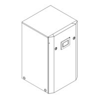
Brine-to-Water Heat Pump
Table of Contents
Advertisement

Dimplex SIK 11 TES Installation And Operating Instruction (72 pages)
Brine-to-Water Heat Pump for Indoor Installation
Table of Contents

Dimplex SIK 11 TES Installation And Operating Instructions Manual (56 pages)
Brine-to-Water Heat Pump for Indoor Installation
Table of Contents
Advertisement
Advertisement