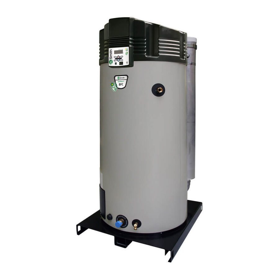
A.O. Smith cyclone BFC - 80 Installation And Service Manual
A.o. smith gas water heater installation user and service manual
Hide thumbs
Also See for cyclone BFC - 80:
- Technical specifications (6 pages) ,
- Installation, user and service manual (104 pages) ,
- Installation, user and service manual (126 pages)
Table of Contents
Advertisement
Installation
Installation
Installation
User and
User and
User and
Service Manual
Service Manual
Service Manual
WATER PRODUCTS
WATER PRODUCTS
WATER PRODUCTS
COMPANY
COMPANY
COMPANY
A DIVISION OF A. O. SMITH CORPORATION
A DIVISION OF A. O. SMITH CORPORATION
A DIVISION OF A. O. SMITH CORPORATION
80
80
100
100
XTRA HIGH EFFICIENCY
XTRA HIGH EFFICIENCY
Advertisement
Table of Contents
Troubleshooting

Related Manuals for A.O. Smith cyclone BFC - 80


Summary of Contents for A.O. Smith cyclone BFC - 80
- Page 1 Installation Installation Installation User and User and User and Service Manual Service Manual Service Manual WATER PRODUCTS WATER PRODUCTS WATER PRODUCTS COMPANY COMPANY COMPANY A DIVISION OF A. O. SMITH CORPORATION A DIVISION OF A. O. SMITH CORPORATION A DIVISION OF A. O. SMITH CORPORATION XTRA HIGH EFFICIENCY XTRA HIGH EFFICIENCY...
- Page 2 www.aosmithinternational.com your installer...
- Page 3 Any brand names mentioned in this manual are registered trademarks of their respective owners. Liability A.O. Smith water Products Company accepts no liability for claims from third parties arising from improper use other than that stated in this manual and in accordance with the General Conditions registered at the Eindhoven Chamber of Commerce.
- Page 4 Instruction manual BFC...
-
Page 5: Table Of Contents
Table of contents Introduction - - - - - - - - - - - - - - - - - - - - - - - - - - - 9 About the appliance - - - - - - - - - - - - - - - - - - - - - - - - - - - - 9 What to do if you smell gas- - - - - - - - - - - - - - - - - - - - - - - - - 9 Regulations - - - - - - - - - - - - - - - - - - - - - - - - - - - - - - - - 9 Target groups - - - - - - - - - - - - - - - - - - - - - - - - - - - - - - 10... - Page 6 Table of contents Starting and running - - - - - - - - - - - - - - - - - - - - - - 53 Introduction - - - - - - - - - - - - - - - - - - - - - - - - - - - - - - - - 53 Starting and running- - - - - - - - - - - - - - - - - - - - - - - - - - - - 53 The appliance's heating cycle - - - - - - - - - - - - - - - - - - - - - - - 53 Shutting down - - - - - - - - - - - - - - - - - - - - - - - - - 55...
- Page 7 16.7 Obligations of A.O. Smith - - - - - - - - - - - - - - - - - - - - - - - - 88 Appendices- - - - - - - - - - - - - - - - - - - - - - - - - - - 89 17.1...
- Page 8 Table of contents Instruction manual BFC...
-
Page 9: Introduction
Introduction About the appliance This manual describes how to install, service and use the BFC appliance. The BFC appliance is a condensing water heater with a fan in the air intake. The BFC can be installed as either an open or room-sealed appliance. A concentric chimney connector is fitted standard to the appliance. -
Page 10: Target Groups
Introduction Furthermore, the installation must comply with the manufacturer's instructions. guidelines published on or prior to the moment of installing, will apply to the installation. Target groups The three target groups for this manual are: • • • Symbols on each page indicate the target groups for whom the information is intended. -
Page 11: Overview Of This Document
Overview of this The table provides an overview of the contents of this document. document Contents of this document Chapter Target groups Working principle of the appliance Installation Filling Draining The control panel Status of the appliance Starting and running Shutting down Main menu Service program... - Page 12 Introduction Instruction manual BFC...
-
Page 13: Working Principle Of The Appliance
Working principle of the appliance Introduction Topics covered in this chapter: • • • • General working The figure shows a cut-away view of the appliance. principle of the Cut-away view of the appliance appliance Legend Only applicable numbers are mentioned. -
Page 14: The Appliance's Heating Cycle
Working principle of the appliance The appliance is equipped with a gas/air premix burner (17). The air is drawn in through the fan (18). The gas is supplied via the gas control (16) on the intake side of the fan. The gas/air mixture is then blown into the burner. The modulated supply of gas and air ensures that the optimum gas/air mixture is always achieved. -
Page 15: Water Temperature Protection
• • 2.4.2 Water temperature protection The electronic controller uses temperatures sensors T1 (7) and T2 (13) to monitor three temperatures that are important for safety. The table explains the functioning of the temperature sensors. Temperature protection Protection Description Against frost The frost protection cuts in. -
Page 16: Safety Of The Installation
2.5.3 T&P valve A T&P valve is only mandatory in an unvented installation. However, A.O. Smith also recommends the use of a T&P valve in vented installations. A T&P (Temperature and Pressure Relief) valve monitors the pressure in the tank and the water temperature at the top of the tank. -
Page 17: Installation
Installation in compliance with the general and local regulations imposed by the gas, water and power supply companies and the fire service. The appliance may only be installed in a room that complies with the requirements stated in national and local ventilation regulations Introduction This chapter describes the installation activities to be carried out before you... - Page 18 Installation 3.3.1 Air humidity and ambient temperature The boiler room must be frost-free, or be protected against frost. The table shows the environmental conditions that must be adhered to for correct functioning of the electronics present in the appliance to be guaranteed. Air humidity and ambient temperature specifications Air humidity and ambient temperature Air humidity...
-
Page 19: Technical Specifications
Working clearances Technical The appliance is supplied without accessories. Check the dimensions specifications and other specifications accessories you plan to use. Instruction manual BFC (3.4.1 "Dimensions of the appliance"), gas data (3.4.2 "General and electrical specifications") IMD-0227 R2 (3.4.3 "Gas data") of any... - Page 20 Installation 3.4.1 Dimensions of the appliance Plan and elevation of appliance (legend: see the table) 45º 18º 45º 11º IMD-0220 R4 Instruction manual BFC...
- Page 21 Dimensions (all measurements in mm unless otherwise indicated) Dimen Description sion Total height Position on pallet Appliance diameter Depth Width Diameter of flue gas outlet Height of flue gas outlet/air supply x position of flue gas outlet y position of flue gas outlet Height of gas connection Height of cold water supply Height of hot water outlet...
- Page 22 Installation 3.4.3 Gas data Gas data Description II 2H3P Natural gas Gas category G20-20 mbar Orifice diameter Nominal load (gross calorific value) Nominal output Supply pressure Burner pressure Gas consumption LP gas Gas category G31-37mbar (propane) Orifice diameter Nominal load (gross calorific value) Nominal output Supply pressure (†)
-
Page 23: Installation Diagram
Installation diagram Installation diagram Legend UNVENTED Only applicable numbers are mentioned. 1. pressure reducing valve (mandatory) 3. T&P valve (mandatory) 4. stop valve (recommended in pipe C and mandatory in pipe A) 5. non-return valve (mandatory) 6. circulation pump (optional) 9. -
Page 24: Water Connections, Vented
Installation Water connections, Vented in compliance with general and local regulations 3.6.1 Cold water side See (A) in the installation diagram 1. Fit an approved stop valve (4) on the cold water side between the cold water 3.6.2 Hot water side See (B) in the installation diagram 1. -
Page 25: Water Connections, Unvented
Water connections, Unvented in compliance with general and local regulations 3.7.1 Cold water side See (A) in the installation diagram 1. Fit an approved stop valve (4) on the cold water side as required by 2. The maximum working pressure of the appliance is 8 bar. Because the 3. -
Page 26: Gas Connection
Installation Gas connection in compliance with general and local regulations enough to supply sufficient capacity to the appliance. See (D) in the installation diagram 1. Fit a manual gas valve (10) in the gas supply pipe. 2. Blow the gas pipe clean before use. 3. - Page 27 Types of appliances IMD-0468 R0 Instruction manual BFC...
- Page 28 Installation Explanation of type of appliance Type of appliance Description Air for combustion is drawn from the boiler room. Concentric and / or parallel wall flue terminal Concentric and / or parallel roof flue terminal Appliances on common air supply and flue gas discharge (concentric and / or parallel) in multi-storey building.
-
Page 29: Specifications
Use of an incorrect roof or wall-mounted flue terminal can cause the installation to malfunction. Instruction manual BFC Caution For type C13 and C33 installations,A.O. Smith prescribes the use of a roof IMD-0286 R2... - Page 30 Installation Concentric wall flue terminal specifications C13 Subject Wall flue terminal set: • 1x wall flue terminal (incl. wall flange & clamping ring) • 1x pipe 500mm • 1x bend 90° Pipe material Pipe diameters No other wall flue terminal is permitted. Use this item number to order the wall conduit set from supplier, manufacturer or wholesaler.
- Page 31 3.9.4 Parallel connections The table states the maximum pipe lengths for parallel systems. The maximum pipe length depends on the chosen diameter. Table of pipe lengths Appliance BFC 80 BFC 100 BFC 80 BFC 100 1) Parallel systems with diameter of 130mm or 150mm. If the maximum total length for a diameter of 130mm is insufficient, 150mm diameter should be used.
-
Page 32: Electrical Connection
Installation Appliance with parallel flue gas discharge material The longest pipe must be used to check the maximum length. In this case, the chimney pipe is the longest. This is 35 metres. This 35 metres is the sum of pipe sections 1, 2, 3, 4 and 5. - Page 33 Optionally, it is possible to connect an isolating transformer, a continuous pump, a program-controlled pump, an extra ON mode switch and an extra alarm signal to the appliance. For these options, see: • • • • consumption stated in the table 3.10.2 Preparation mains phase (L) to the phase of the appliance, and the mains neutral (N) to the...
- Page 34 Installation In preparation, you must first remove the two plastic covers and the protective cap of the electrical section. 1. Undo the screws of the plastic covers. 2. Carefully remove the covers from the appliance. 3. Loosen the 2 screws (A) of the electrical section, and remove the protective the electrical component connections.
-
Page 35: Checking The Supply Pressure And Burner Pressure
4. If you have no more connections to make: 5. Connect the power cable to the isolator. 3.10.5 Connecting a program-controlled pump 1. Connect phase (L), neutral (N) and earth ( ) to terminals 10, 11 and 12 as 2. Fit the cable in the strain relief. 3. - Page 36 Installation Gas control Legend Only applicable numbers are mentioned. 1. supply pressure test nipple 2. burner pressure test nipple 3. burner pressure regulator 4. burner pressure control cap 5. burner pressure control adjusting screw 3.11.1 Preparation To check the supply pressure and burner pressure, proceed as follows: 1.
- Page 37 MENU ^ ON È WEEK PROGRAM 7. Activate the "ON mode" by going through the following steps: ^ CHANGE SETPOINT È 8. Once the display shows the text RUNNING you must wait about 1 minute 9. Use the pressure gauge to read the supply pressure at 1nipple 10.
- Page 38 Installation 3.11.3 Adjusting the pressure 1. Remove the cap (4) from the burner pressure regulator (3). 2. Correct the burner pressure by turning the adjusting screw (5), depending 3. Cover the opening of the adjusting screw and check the burner pressure 4.
-
Page 39: Conversion To A Different Gas Category
Conversion to a different gas category engineer. If the appliance must operate on a family of gases (LP gas or natural gas) or other gas category than that for which the appliance has been set at the factory, the appliance will have be adapted using a special conversion kit. conversion is complete. - Page 40 Conversion to a different gas category 5. Detach the 3-part gas coupling (2) adjacent to the burner. 6. Select and fit the correct orifice from the conversion kit, based on the gas 7. Refit the 3-part gas coupling (2). 8. Check the burner pressure and supply pressure 9.
-
Page 41: Filling
Filling Installation diagram Legend UNVENTED Only applicable numbers are mentioned. 1. pressure reducing valve (mandatory) 3. T&P valve (mandatory) 4. stop valve (recommended in pipe C and mandatory in pipe A) 5. non-return valve (mandatory) 6. circulation pump (optional) 9. drain valve 10. -
Page 42: Filling The Appliance
Filling Filling the appliance 5.1.1 Filling unvented installations To fill the appliance, proceed as follows: 1. Open the stop valve (11) in the hot water pipe and, if present, the stop valves 2. Close the drain valve (9). 3. Open the nearest hot water draw-off point (14). 4. -
Page 43: Draining
Draining Installation diagram Legend UNVENTED Only applicable numbers are mentioned. 1. pressure reducing valve (mandatory) 3. T&P valve (mandatory) 4. stop valve (recommended in pipe C and mandatory in pipe A) 5. non-return valve (mandatory) 6. circulation pump (optional) 9. drain valve 10. -
Page 44: Draining Unvented Installations
Draining Draining unvented installations 1. Activate the MENU with MENU ^ ON È WEEK PROGRAM 2. Position the cursor in front of OFF. 3. Confirm OFF with 4. Wait until the fan has stopped. The symbol appliance. 5. Switch the appliance OFF (position 0) using the ON/OFF switch on the 6. - Page 45 6. Isolate the water heater from the power supply by putting the isolator 7. Shut off the gas supply (10). 8. Close the stop valve (11) in the hot water pipe. 9. Close the stop valve (4) between the water tank and the cold water inlet (A). 10.
- Page 46 Draining Instruction manual BFC...
-
Page 47: The Control Panel
The control panel Introduction Topics covered in this chapter: • Controls; • Meaning of icons; • Electronic controller ON/OFF switch; • Navigation buttons; • connection. Controls <The entire appliance is controlled (and monitored) by the ThermoControl (electronic controller).The figure shows the electronic controller. 0063 IMD-0423 R0 The control panel is completely menu-driven, and... -
Page 48: Pc Connection
PC connection The PC connection is solely intended to enable technicians from A.O. Smith to display the status and history of the appliance. These details can be important for troubleshooting and/or responding to complaints. -
Page 49: Status Of The Appliance
Status of the appliance Introduction Topics covered in this chapter: • Operating modes; • Error conditions; • Service condition. Operating modes When running, the appliance has four basic operating modes, namely: • • • EXTRA • PROG 8.2.1 In this mode, the frost protection is activated. The figure shows the display with the following information: •... -
Page 50: Error Conditions
Status of the appliance 8.2.4 PROG In this mode a preset week program is active, and the appliance responds continually to demand within the time periods set in the week program. There are two distinct situations possible in this mode: PROG 10:00 Monday 76ÉC... -
Page 51: Service Condition
Service condition The figure shows the message WARNING MAX. BURNING HOURS: SERVICE REQUIRED SERVICE REQUIRED.Should this message appear, then the appliance is in need of a service and maintenance inspection. In that case, contact your service and maintenance engineer. Note The message SERVICE REQUIREDis based on the number of expired burning hours and the preset service interval. - Page 52 Status of the appliance Instruction manual BFC...
-
Page 53: Starting And Running
Starting and running Introduction Topics covered in this chapter, in sequence: • Starting and running. • The appliance's heating cycle. Starting and running Start the appliance as follows: 1. Fill the appliance "Filling"). 2. Open (3.5 "Installation diagram") the manual gas valve. - Page 54 Starting and running Once the appliance starts, it will run through the following steps: 1. The water temperature drops below the set temperature of (for example) 65°C. The electronic controller detects a demand and starts the heating cycle. The icon is activated.
-
Page 55: Shutting Down
Shutting down 10.1 Introduction This chapter describes: • Shut the appliance down for a brief period ("OFF mode"); • Electrically isolating the appliance; • Shutting the appliance down for a long 10.2 Shut the appliance down for a brief period ("OFF mode") To shut the appliance down for a brief period, you must activate the frost protection. - Page 56 Shutting down Instruction manual BFC...
-
Page 57: Main Menu
Main menu 11.1 Notational convention for menu-related instructions The MENU ( ) of the electronic controller is divided into submenus. For example, SETTINGS is one of the functions reached from the main menu. The SETTINGS menu is divided into submenus in turn. For example, LANGUAGE is a submenu of SETTINGS. -
Page 58: Starting And Stopping The Week Program
Main menu The appliance's default week program switches the appliance on every day at 00:00 and off at 23:59. The default water temperature setting is 65°C. If you want, you can change every setting in the appliance's standard week program. If the water temperature becomes too low while the week program is running, the appliance will run through the heating cycle... -
Page 59: Adding Times To A Week Program
Confirm with The cursor moves to the minute digits, which flash. SU 08»00 SU 08:00 Tset 65ÉC PUMP ON SAVE Note Because the switch-off time can never be earlier than the switch-on time, the switch-off time setting is automatically adjusted with the switch-on time. 4. -
Page 60: Deleting Times From A Week Program
Main menu The display shows the menu for the week program. The cursor points to the active period. DAY TIME Tset ON »SU 08:15 75ÉC P OFF SU 12:45 00:00 65ÉC P OFF SA 23:59 INSERT DELETE START OPERATION 2. Scroll to INSERT. -
Page 61: Extra Period
Confirm with DAY TIME Tset ON !SU 18:00 75ÉC P OFF SU 22:00 00:00 65ÉC P OFF MO 23:59 OFF SA 23:59 INSERT DELETE START OPERATION 5. The lines showing switch-on/off times are replaced by the text DELETE BLOCK?. See the figure. Confirm with (or use to cancel) -
Page 62: Settings
Main menu Setting the switch-off time 1. Use to set the hours. In the example, this is 012. Confirm with The cursor moves to the minute digits, which flash. SU 08:15 SU 12»15 Tset 65ÉC PUMP ON START 2. Use to set the minutes. - Page 63 11.11.2 Setting day and time To enter the time and day: MENU WEEK PROGRAM ^ EXTRA PERIOD È»SETTINGS 1. Call up the menu for entering the day and time as follows: : SETTINGS. Confirm with The display shows the menu for settings. 3.
- Page 64 Main menu The relevant display appears. REGULATION INTERVAL 80ÉC Instruction manual BFC...
-
Page 65: Service Program
Service program 12.1 Introduction The service program is used by the installation engineer or service and maintenance engineer for: • Setting the hysteresis; • Displaying the error history; • Displaying the appliance history; • Display the selected appliance; • Switching the pump on or off;... -
Page 66: Displaying The Appliance History
Service program 12.4 Displaying the appliance history The appliance history submenu is used to display the burning hours, the number of ignitions, the number of flame errors and the number of ignition errors. Call up the menu for displaying the appliance history as follows: •... -
Page 67: Troubleshooting
Troubleshooting 13.1 Introduction A distinction is made between: • • S02: SENSOR ERROR S02: SEMSOR ERROR Instruction manual BFC General errors General errors are not reported on the display. General errors are: Gas smell Display does not light up Insufficient or no hot water. Water leakage Explosive ignition. -
Page 68: Troubleshooting Table For General Errors
13.2 Troubleshooting table for general errors Warning Maintenance may only be performed by a qualified service and maintenance engineer. General errors Symptom Cause Solution Gas smell Gas leak Display is off Appliance is turned off Start the appliance up No supply voltage 1. - Page 69 Symptom Cause Solution Water leakage Leakage from a water Tighten the threaded connection connection (threaded) Condensate leakage Check that the condensation water discharge is working properly. Rectify if necessary Leakage from another Trace the leak nearby water appliance or pipe segment Leakage from the Consult the supplier and/or manufacturer appliance's tank...
-
Page 70: Displayed Errors
13.3 Displayed errors Code + Description Cause Solution S01 (blocking error) Sensor is not (correctly) Connect the sensor lead to JP3 connected Open circuit from Damaged cable or Replace the sensor temperature sensor T2 defective sensor at bottom of the tank S02 (blocking error) Sensor is not (correctly) Connect the sensor lead to JP5... - Page 71 Code + Description Cause Solution S12 (blocking error) Short circuit in sensor Replace sensor T circuit Short circuit in sensor 1 of temperature sensor at the top of the tank S13 (blocking error) Short circuit in sensor Replace sensor T circuit Short circuit in sensor 2 of temperature sensor...
- Page 72 Code + Description Cause Solution F02 (lock out error) Defective motor and/or 1. Check the motor and rotor rotor. 2. Replace the fan if the motor or rotor is defective. Fan fails to run at 3. Reset appliance controller correct speed. Damaged wiring 1.
- Page 73 Code + Description Cause Solution Air pressure switch fails Air pressure switch 1. Check the wiring between the air pressure switch and the to close during pre- leads purge. 2. Reset appliance controller Loose air pressure 1. Check hoses between air pressure switch and burner/fan. switch hoses 2.
- Page 74 Code + Description Cause Solution Fan speed too low 1. Check the fan speed 2. If the fan speed is too low, check the settings 3. If the settings are correct, then replace the fan. 4. Modify the settings if incorrect 5.
- Page 75 Code + Description Cause Solution F03 (lock out error) Damaged wiring/Open 1. Check the wiring between the pressure switch and the circuit The pressure switch 2. If necessary, replace the wiring fails to work correctly Pressure switch not 1. Check the running speed of the fan closing 2.
- Page 76 Code + Description Cause Solution F04 (lock out error) No gas 1. Open the main gas valve and/or the manual gas valve supplying Three unsuccessful 2. Check the supply pressure to the gas control ignition attempts. 3. If necessary, repair the gas supply Air in the gas pipes Bleed the air out of the gas pipe No burner pressure...
- Page 77 Code + Description Cause Solution F06 (lock out error) Damaged cable in Check the wiring of the flame probe. If necessary, replace the contact with metal wiring. surface. Short circuit between flame probe and earth Ceramic part of the 1. Check that the ceramic part of the flame probe is still intact in flame probe is broken/cracked.
- Page 78 Code + Description Cause Solution F10 (lock out error) Pressure switch not 1. Check the running speed of the fan closing Restriction on the 2. Check that the hoses on the pressure switch and the air supply number of ignition attempts based on pressure switch state changes.
- Page 79 Code + Description Cause Solution C02 (lock out error) Incorrect reference 1. Reset electronic controller. voltage from the AD 2. Check that the frequency of the power supply is converter. Error message from the appliance controller. 3. If the frequency is correct but the error persists, replace the Internal error message •...
- Page 80 Code + Description Cause Solution E01 (blocking error) The temperature of the None. This is a temporary message that may appear from time to water at the top of the time, but will disappear automatically. tank is > 85 The temperature protection at the top of the tank has been activated.
-
Page 81: Maintenance Frequency
Maintenance frequency 14.1 Introduction A service should be carried out at least once a year, both on the water side and on the gas side. Maintenance frequency depends, among other things, on the water quality, the average burning time per day and the set water temperature. To determine the correct maintenance frequency, it is recommended to arrange for the service and maintenance engineer to check the appliance on both the water and gas side, three months after installation. - Page 82 Maintenance frequency Instruction manual BFC...
-
Page 83: Performing Maintenance
Performing maintenance 15.1 Introduction maintenance engineer. At each service, the appliance undergoes maintenance on both the water side and the gas side. The maintenance must be carried out in the following order. model, and the full serial number of the appliance. These details can be found on the rating plate. - Page 84 Performing maintenance 6. Switch the electronic controller ON by setting the ON/OFF switch to MENU ^ ON È WEEK PROGRAM 7. Activate "ON mode" by going through the following steps: 8. If there is no heat demand, increase Tset 9. Check whether the heating cycle runs correctly 10.
-
Page 85: Water-Side Maintenance
17. Check the drain pipes from the discharge points of all valves and remove 18. Drain the appliance (see Draining). 15.3 Water-side maintenance 15.3.1 Introduction The following steps must be carried out on the water side: 15.3.2 Checking the anodes Timely replacement of the anodes extends the service life of the appliance. -
Page 86: Gas-Side Maintenance
Performing maintenance 6. Close the cleaning opening. To avoid damage to the tank, tighten the bolts 15.3.4 Cleaning condensation water discharge Regular cleaning of the condensation drain and siphon is essential for prevention of blockages. 15.4 Gas-side maintenance 15.4.1 Introduction The following steps must be carried out on the gas side: 15.4.2 Clean the burner(s) -
Page 87: Warranty (Certificate)
A.O. Smith water Products Company B.V. of Veldhoven, The Netherlands (hereinafter "A.O. Smith") the right to the warranty set out below, defining the commitments of A.O. Smith to the owner. 16.1 General warranty If within one year of the original installation date of a water heater supplied by A.O. -
Page 88: Exclusions
Smith warranty expressly set out in this Certificate. Under the terms of the supplied warranty, A.O. Smith is not liable for damage to persons or property caused by (sections or parts, or the glass-lined steel tank of) a (replacement) water heater that it has supplied. -
Page 89: Appendices
Appendices 17.1 Introduction This appendix contains: • • Instruction manual BFC Electrical diagram (17.2 "BFC Electrical Diagram.") Week program card... -
Page 90: Bfc Electrical Diagram
Appendices 17.2 BFC Electrical Diagram. 1 = brown, 2 = blue, 3 = green, 4 = black, 5 = white, 6 = grey/beige, 7 = red, 8 = green Instruction manual BFC... - Page 91 TERMINAL BLOCK CONNECTIONS: N Neutral L Phase input of controller COMPONENTS: A Controller B Flame probe C Hot surface igniter D Gas control E Burner earth connection F Extra ON mode switch G Program-controlled pump H External error signal connection K Double-pole isolator L Controller 0/I switch M Display...
- Page 92 Appendices Instruction manual BFC...
-
Page 93: Week Program Card
17.3 Week program card You can cut the week program card out and keep it near the appliance. Period TIME Example Period TIME 14:30 16:15 Instruction manual BFC Tset Pump Period ...°C ON / OFF ...°C ON / OFF ...°C ON / OFF ...°C ON / OFF... - Page 94 Instruction manual BFC...
- Page 95 Index ambient temperature 18 appliance displaying history 66 displaying selection 66 general working principle 13 heating cycle 14 protection 14 types 9, 17 burner pressure 35 claims 88 connect 24, 25 air supply 26 Alarm OUT 35 circulation piping 24, 25 cold water side 24, 25 condensation drainage 24, 25 electrical 32...
- Page 96 Index mode ERROR 50 EXTRA 49 HEAT DEMAND 53 IGNITION 53 OFF 49 ON 49 POST-PURGE 53 PRE-GLOW 53 PRE-PURGE 53 PRESSURE SWITCH 53 PROG 50 RUNNING 53 SERVICE REQUIRED 51 navigation buttons 47 off 49 on 49 ON mode 57 on/off switch 47 operating modes EXTRA 49...