
Related Manuals for Miller Wildcat 200


Summary of Contents for Miller Wildcat 200
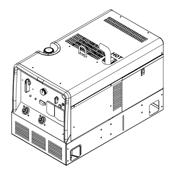
- Page 1 OM-237 711C 2009−01 Processes Stick (SMAW) Welding Non-Critical TIG (GTAW) Welding Description Engine Driven Welding Generator Wildcat 200 ™ File: Engine Drive Visit our website at www.MillerWelds.com...
- Page 2 We know you don’t have time to do it any other way. That’s why when Niels Miller first started building arc welders in 1929, he made sure his products offered long-lasting value and superior quality.
-
Page 3: Table Of Contents
TABLE OF CONTENTS SECTION 1 − SAFETY PRECAUTIONS − READ BEFORE USING ....... . 1-1. - Page 4 TABLE OF CONTENTS 8-5. Adjusting Engine Speed ............. . . 8-6.
-
Page 5: Section 1 − Safety Precautions − Read Before Using
SECTION 1 − SAFETY PRECAUTIONS − READ BEFORE USING rom_2008−08 Protect yourself and others from injury — read and follow these precautions. 1-1. Symbol Usage DANGER! − Indicates a hazardous situation which, if Indicates special instructions. not avoided, will result in death or serious injury. The possible hazards are shown in the adjoining symbols or explained in the text. - Page 6 D Do not weld on closed containers such as tanks, drums, or pipes, FUMES AND GASES can be hazardous. unless they are properly prepared according to AWS F4.1 (see Safety Standards). Welding produces fumes and gases. Breathing these D Do not weld where the atmosphere may contain flammable dust, fumes and gases can be hazardous to your health.
-
Page 7: Engine Hazards
1-3. Engine Hazards HOT PARTS can cause severe burns. BATTERY EXPLOSION can BLIND. D Do not touch hot parts bare handed. D Always wear a face shield, rubber gloves, and protective clothing when working on a battery. D Allow cooling period before working on equip- ment. -
Page 8: Compressed Air Hazards
D Keep hands, hair, loose clothing, and tools away from moving HYDRAULIC FLUID can injure or kill. parts. D Before working on hydraulic system, turn off and lockout/tagout D Before working on hydraulic system, turn off and unit, release pressure, and be sure hydraulic pressure cannot be lockout/tagout unit, release pressure, and be sure accidentally applied. -
Page 9: Additional Symbols For Installation, Operation, And Maintenance
MOVING PARTS can injure. HOT PARTS can cause severe burns. D Do not touch hot compressor or air system D Keep away from fans, belts and rotors. parts. D Keep all doors, panels, covers, and guards D Let system cool down before touching or ser- closed and securely in place. -
Page 10: California Proposition 65 Warnings
H.F. RADIATION can cause interference. ARC WELDING can cause interference. D High-frequency (H.F.) can interfere with radio D Electromagnetic energy can interfere with navigation, safety services, computers, and sensitive electronic equipment such as micro- communications equipment. processors, computers, and computer-driven equipment such as robots. -
Page 11: Section 2 − Consignes De Sécurité − Lire Avant Utilisation
SECTION 2 CONSIGNES DE SÉCURITÉ − LIRE AVANT − UTILISATION rom_2008−08fre Se protéger, ainsi que toute autre personne travaillant sur les lieux, contre les étincelles et le métal chaud. 2-1. Signification des symboles DANGER! − Indique une situation dangereuse qui si on Indique des instructions spécifiques. - Page 12 D Porter un casque de soudage approuvé muni de verres filtrants DES PIÈCES CHAUDES peuvent approprié pour protéger visage et yeux pendant le soudage provoquer des brûlures graves. (voir ANSI Z49.1 et Z87.1 énuméré dans les normes de sécurité). D Porter des lunettes de sécurité avec écrans latéraux même sous D Ne pas toucher à...
-
Page 13: Dangers Existant En Relation Avec Le Moteur
D Placer les bouteilles debout en les fixant dans un support station- LES CHAMPS MAGNETIQUES peuvent naire ou dans un porte-bouteilles pour les empêcher de tomber ou affecter des implants médicaux. de se renverser. D Tenir les bouteilles éloignées des circuits de soudage ou autres D Porteur de simulateur cardiaque ou autre im- circuits électriques. -
Page 14: Dangers Liés À L'hydraulique
L’utilisation d’un groupe autonome L’ACIDE DE LA BATTERIE peut pro- à l’intérieur PEUT VOUS TUER EN voquer des brûlures dans les YEUX et QUELQUES MINUTES. sur la PEAU. D Ne pas renverser la batterie. D Les fumées d’un groupe autonome contient du D Remplacer une batterie endommagée. -
Page 15: Dangers Liés À L'air Comprimé
LIRE LES INSTRUCTIONS. D Lire le manuel d’utilisation avant d’installer, d’utiliser ou d’intervenir sur l’appareil. D N’utiliser que les pièces de rechange recommandées par le constructeur. D Effectuer l’entretien en respectant les manuels d’utilisation, les normes industrielles et les codes nationaux, d’état et locaux. 2-5. -
Page 16: Dangers Supplémentaires En Relation Avec L'installation, Le Fonctionnement Et La Maintenance
MÉTAL CHAUD provenant LIRE LES INSTRUCTIONS. découpage ou du gougeage à l’arc risque de provoquer un incendie ou une explosion. D Lire le manuel d’utilisation avant d’installer, d’utiliser ou d’intervenir sur l’appareil. D Ne pas découper ou gouger à proximité D N’utiliser que les pièces de rechange de produits inflammables. -
Page 17: Proposition Californienne 65 Avertissements
LE RAYONNEMENT HAUTE FRÉ- LE SOUDAGE À L’ARC risque de QUENCE (H.F.) risque de provoquer provoquer des interférences. des interférences. D L’énergie électromagnétique risque de provo- quer des interférences pour l’équipement élec- D Le rayonnement haute fréquence (H.F.) peut tronique sensible tel que les ordinateurs et provoquer des interférences avec les équipe- l’équipement commandé... -
Page 18: Information Emf
2-9. Information EMF Considérations sur le soudage et les effets de basse fréquence et des 1. Garder les câbles ensemble, les torsader, les scotcher, ou les champs magnétiques et électriques. recouvrir d’une housse. Le courant de soudage, pendant son passage dans les câbles de sou- 2. -
Page 19: Section 3 − Definitions
A complete Parts List is available at www.MillerWelds.com SECTION 3 − DEFINITIONS 3-1. Symbol Definitions Fast Fast/Slow Stop Engine Slow (Idle) (Run, Weld/Power) (Run/Idle) Read Operator’s Start Engine Amperes Volts Manual Engine Oil Fuel Battery (Engine) Engine Check Valve Do not switch while Engine Choke Work Connection Clearance... -
Page 20: Dimensions, Weights, And Operating Angles
A complete Parts List is available at www.MillerWelds.com 4-3. Dimensions, Weights, And Operating Angles Do not exceed tilt angles or engine could be damaged or unit could tip. ° Do not move or operate unit where it could tip. Weight: 350 lb (159 kg) °... -
Page 21: Duty Cycle
A complete Parts List is available at www.MillerWelds.com 4-4. Duty Cycle Duty cycle is the percentage of 10 minutes that unit can weld at rated load without overheating. NOTICE − Exceeding duty cycle can damage unit and void warranty. This unit is rated for 100% duty cycle at 150 amperes (continuous welding) and 20% duty cycle at 200 amperes (two minutes welding,... -
Page 22: Fuel Consumption
A complete Parts List is available at www.MillerWelds.com 4-5. Fuel Consumption Welding at 50% of rated load, fuel consumption is approximately 0.64 gal (2.41 L) per hour. Welding at 75% of rated load, fuel consumption is approximately 0.77 gal (2.92 L) per hour. Welding at 100% of rated load, fuel consumption is approximately 0.94 gal (3.55 L) per hour. -
Page 23: Generator Power Curve
A complete Parts List is available at www.MillerWelds.com 4-7. Generator Power Curve The generator power curve shows the generator power in amperes available at the receptacles. 237 718-A OM-237 711 Page 19... -
Page 24: Section 5 − Installation
A complete Parts List is available at www.MillerWelds.com SECTION 5 − INSTALLATION 5-1. Installing Welding Generator Do not move or operate unit where it could tip. Do not lift unit from end. Movement Do not weld on base. Welding on base can cause fuel tank fire or explosion. -
Page 25: Installing Exhaust Pipe
A complete Parts List is available at www.MillerWelds.com 5-2. Grounding Generator To Truck Or Trailer Frame Always ground generator frame to vehicle frame to pre- vent electric shock and static electricity hazards. Also see AWS Safety & Health Fact Sheet No. 29, Grounding of Portable And Vehicle Mounted Welding Generators. -
Page 26: Engine Prestart Checks
A complete Parts List is available at www.MillerWelds.com 5-4. Engine Prestart Checks Full Gasoline Full 803 754-D / 217 015-A Check all fluids daily. Engine must be cold Fuel operate erratically if crankcase is over- and on a level surface. Unit is shipped with filled. -
Page 27: Connecting Or Replacing The Battery
A complete Parts List is available at www.MillerWelds.com 5-5. Connecting Or Replacing the Battery Connect negative (−) battery cable last. To connect battery, remove battery ac- cess panel. Battery Holddown To change battery, remove battery ac- cess panel and battery holddown. Be sure battery cables are not pinched when installing battery. -
Page 28: Weld Output Terminals
A complete Parts List is available at www.MillerWelds.com 5-6. Weld Output Terminals Stop engine. Negative (−) Weld Output Terminal Positive (+) Weld Output Terminal For Direct Current Electrode Positive (DCEP), connect work cable to Neg- ative (−) terminal and electrode hold- er to Positive (+) terminal. -
Page 29: Selecting Weld Cable Sizes
A complete Parts List is available at www.MillerWelds.com 5-8. Selecting Weld Cable Sizes* Weld Cable Size** and Total Cable (Copper) Length in Weld Circuit Not Exceeding*** 150 ft 200 ft 250 ft 300 ft 350 ft 400 ft 100 ft (30 m) or Less (45 m) (60 m) (70 m) -
Page 30: Section 6 − Operating The Welding Generator
A complete Parts List is available at www.MillerWelds.com SECTION 6 − OPERATING THE WELDING GENERATOR 6-1. Front Panel Controls (See Section 6-2) 805 356 / 237 335-A OM-237 711 Page 26... -
Page 31: Front Panel Control Descriptions (See Section 6-1)
A complete Parts List is available at www.MillerWelds.com 6-2. Front Panel Control Descriptions (See Section 6-1) Engine Control Switch To Start (Recoil): pull out choke and turn En- Negative hours are shown when engine is gine Control switch to Run or Run/Idle posi- Use switch to start engine, select speed, and past recommended oil change interval. -
Page 32: Cold Weather Engine Operation
A complete Parts List is available at www.MillerWelds.com 6-4. Cold Weather Engine Operation Engine Control Switch Carburetor Icing Carburetor icing causes the unit to drop Infrequently below the normal idle speed and then Loaded stall. This condition occurs when the temperature is near freezing and the rel- ative humidity is high. -
Page 33: Section 7 − Operating Auxiliary Equipment
A complete Parts List is available at www.MillerWelds.com SECTION 7 − OPERATING AUXILIARY EQUIPMENT 7-1. Standard Receptacles CB1 protects receptacles RC1, RC2, and If a ground fault is detected, the GFCI Re- If unit does not have GFCI recep- RC3 from overload. If CB1 opens, the re- set button pops out and the circuit opens to tacles, use GFCI-protected exten- ceptacles do not work. -
Page 34: Wiring Optional 240 Volt Plug
A complete Parts List is available at www.MillerWelds.com 7-2. Wiring Optional 240 Volt Plug The plug can be wired for a 240 V, 2-wire load or a 120/240V, 3-wire load. See circuit diagram. Plug Wired for 120/240 V, 3-Wire Load Current Available in Amperes When wired for 120 V loads, each duplex receptacle shares a load... -
Page 35: Section 8 − Maintenance
A complete Parts List is available at www.MillerWelds.com SECTION 8 − MAINTENANCE 8-1. Routine Maintenance Stop engine before maintaining. See Engine Manual and Maintenance Label Recycle engine for important start-up, service, and storage fluids. information. Service engine more often if used in severe conditions. -
Page 36: Maintenance Label
A complete Parts List is available at www.MillerWelds.com 8-2. Maintenance Label Maintenance label is located on inside of engine access door. OM-237 711 Page 32... -
Page 37: Servicing Air Cleaner
A complete Parts List is available at www.MillerWelds.com 8-3. Servicing Air Cleaner Stop engine. Do not run engine without air cleaner or with dirty element. Cover Screw Cover Element Wash element with soap and water solution. Allow element to air dry completely. -
Page 38: Changing Engine Oil And Fuel Filter
A complete Parts List is available at www.MillerWelds.com 8-4. Changing Engine Oil And Fuel Filter Stop engine and let cool. Oil Drain Valve 1/2 ID x 12 in. (305 mm) Hose Change engine oil according to en- gine owner’s manual. NOTICE −... -
Page 39: Adjusting Engine Speed
A complete Parts List is available at www.MillerWelds.com 8-5. Adjusting Engine Speed After tuning engine, check engine speeds with a tachometer (see table). If necessary, adjust speeds as follows: 2200 − 2300 rpm Make speed adjustments with (36.6 − 38.3 Hz) Fine control in Max position 3675 −... -
Page 40: Overload Protection
A complete Parts List is available at www.MillerWelds.com 8-6. Overload Protection Stop engine. Disconnect negative (−) battery cable. Fuse F1 F6 protects the engine wiring sys- tem from overload. If F1 opens, engine will not crank. Replace open fuse. Reinstall cover before operating. -
Page 41: Section 9 − Troubleshooting
A complete Parts List is available at www.MillerWelds.com SECTION 9 − TROUBLESHOOTING 9-1. Welding Troubleshooting Trouble Remedy Low or no weld output; generator pow- Check control settings. er output okay at AC receptacles. Check weld connections. Have Factory Authorized Service Agent check brushes, slip rings, capacitor C1, and integrated recti- fier SR1. -
Page 42: Engine Troubleshooting
A complete Parts List is available at www.MillerWelds.com Trouble Remedy Erratic power output at AC recept- Check fuel level. acles. Check engine speed, and adjust if necessary (see Section 8-5). Check receptacle wiring and connections. Have Factory Authorized Service Agent check brushes and slip rings. 9-3. -
Page 43: Section 10 − Parts List
A complete Parts List is available at www.MillerWelds.com Trouble Remedy Battery Discharges between uses. Clean battery, terminals, and posts with baking soda and water solution; rinse with clear water. Periodically recharge battery (approximately every 3 months). Replace battery. Check voltage regulator and connections according to engine manual. Engine idles but does not come up to Have Factory Authorized Service Agent check hour meter/idle module, and current transformer CT1. -
Page 44: Section 11 − Electrical Diagrams
SECTION 11 − ELECTRICAL DIAGRAMS 237 632-C Figure 11-1. Circuit Diagram For Welding Generator OM-237 711 Page 40... -
Page 45: Section 12 − Generator Power Guidelines
SECTION 12 − GENERATOR POWER GUIDELINES The views in this section are intended to be representative of all engine-driven welding generators. Your unit may differ from those shown. 12-1. Selecting Equipment Generator Power Receptacles − Neutral Bonded To Frame 3-Prong Plug From Case Grounded Equipment 2-Prong Plug From Double Insulated Equipment... - Page 46 12-3. Grounding When Supplying Building Systems Equipment Grounding Terminal Grounding Cable Use #10 AWG or larger insulated copper wire. Ground Device GND/PE Use ground device as stated in electrical codes. Ground generator to system earth ground if supplying power to a premises (home, shop, farm) wiring system.
- Page 47 12-5. Approximate Power Requirements For Industrial Motors Industrial Motors Rating Starting Watts Running Watts Split Phase 1/8 HP 1/6 HP 1225 1/4 HP 1600 1/3 HP 2100 1/2 HP 3175 Capacitor Start-Induction Run 1/3 HP 2020 1/2 HP 3075 3/4 HP 4500 1400 1 HP...
- Page 48 12-7. Approximate Power Requirements For Contractor Equipment Contractor Rating Starting Watts Running Watts Hand Drill 1/4 in 3/8 in 1/2 in Circular Saw 6-1/2 in 7-1/4 in 8-1/4 in 1400 1400 Table Saw 9 in 4500 1500 10 in 6300 1800 Band Saw 14 in...
- Page 49 12-8. Power Required To Start Motor Single-Phase Induction Motor Starting Requirements Motor Start Code KVA/HP 10.0 11.2 12.5 14.0 Motor Start Code Running Amperage Motor HP Motor Voltage To find starting amperage: Step 1: Find code and use table to find kVA/HP.
- Page 50 12-10. Typical Connections To Supply Standby Power Have only qualified persons perform these connections according to all applicable codes and safety practices. Properly install and ground this equipment according to its Owner’s Manual and na- Fused tional, state, and local codes. Welding Utility Disconnect...
- Page 51 12-11. Selecting Extension Cord (Use Shortest Cord Possible) Cord Lengths for 120 Volt Loads If unit does not have GFCI receptacles, use GFCI-protected extension cord. Maximum Allowable Cord Length in ft (m) for Conductor Size (AWG)* Current Load (Watts) (Amperes) 350 (106) 225 (68) 137 (42)
-
Page 52: Section 13 − Stick Welding (Smaw) Guidelines
SECTION 13 − STICK WELDING (SMAW) GUIDELINES 13-1. Stick Welding Procedure Weld current starts when electrode touches work- piece. Equipment Needed: Tools Needed: Weld current can damage electronic parts in vehicles. Disconnect both battery cables before welding on a vehicle. Place work clamp as close to the weld as possible. - Page 53 13-2. Electrode and Amperage Selection Chart 6010 DEEP 3/32 MIN. PREP, ROUGH HIGH SPATTER 6011 DEEP 6010 5/32 & 6013 EP,EN GENERAL 3/16 6011 7/32 SMOOTH, EASY, 7014 EP,EN FAST 1/16 LOW HYDROGEN, 7018 5/64 STRONG 3/32 FLAT SMOOTH, EASY, 7024 EP,EN HORIZ...
- Page 54 13-4. Positioning Electrode Holder End View Of Work Angle Side View Of Electrode Angle ° ° ° ° Groove Welds ° ° ° ° Fillet Welds S-0060 13-5. Poor Weld Bead Characteristics Large Spatter Deposits Rough, Uneven Bead Slight Crater During Welding Bad Overlap Poor Penetration S-0053-A...
- Page 55 13-7. Conditions That Affect Weld Bead Shape Weld bead shape is affected electrode angle, length, travel speed, and thickness of base metal. Correct Angle Angle Too Large ° - ° Angle Too Small Electrode Angle Drag Spatter Arc Length Normal Too Long Too Short Travel Speed...
- Page 56 13-9. Butt Joints Tack Welds Prevent edges of joint from draw- ing together ahead of electrode by tack welding the materials in posi- tion before final weld. Square Groove Weld Good for materials up to 3/16 in. (5 mm) thick. Single V-Groove Weld Good for materials 3/16 −...
- Page 57 13-12. Weld Test Vise Weld Joint Hammer Strike weld joint in direction shown. A good weld bends over but does not break. 2 To 3 in. (51-76 mm) 2 To 3 in. (51-76 mm) 1/4 in. (6.4 mm) S-0057-B 13-13. Troubleshooting Porosity −...
- Page 58 Lack Of Penetration − shallow fusion between weld metal and base metal. Lack of Penetration Good Penetration Possible Causes Corrective Actions Improper joint preparation. Material too thick. Joint preparation and design must provide access to bottom of groove. Improper weld technique. Keep arc on leading edge of weld puddle.
- Page 59 Effective January 1, 2009 (Equipment with a serial number preface of LK or newer) This limited warranty supersedes all previous Miller warranties and is exclusive with no other Warranty Questions? guarantees or warranties expressed or implied. LIMITED WARRANTY − Subject to the terms and conditions...
- Page 60 Contact the Delivering Carrier to: File a claim for loss or damage during shipment. For assistance in filing or settling claims, contact your distributor and/or equipment manufacturer’s Transportation Department. © ORIGINAL INSTRUCTIONS − PRINTED IN USA 2009 Miller Electric Mfg. Co. 2009−01...