Vector TCI-W11-H Overview
Universal controller
Hide thumbs
Also See for TCI-W11-H:
- Quick start manual (4 pages) ,
- Manual (23 pages) ,
- Manual (18 pages)
Table of Contents
Advertisement
Quick Links
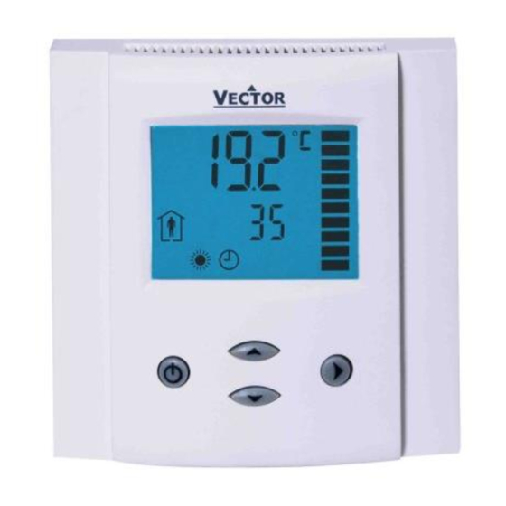
TCI-W Universal Controller
Applications
•
Fan coil units
•
Heat exchangers
•
Zoning
General
•
TCI-W11: 1 independent control loop, 1 internal temperature sensor, 1 universal input (analog/binary/temp), 2
binary outputs, 1 analog output
•
TCI-W22: 2 independent control loops, 1 internal temperature sensor, 2 universal inputs, 2 binary outputs, 1
analog output.
•
Internal temperature sensor standard. Add replaceable humidity element as required: AES3-HT-A2 (2%), AES3-
HT-A3 (3%), or AES3-HT-A5 (5%)
•
Flexible application configuration is made with a parameter-setting routine using the standard operation terminal.
Name
- W
T
C
I
2
Ordering
Stock
Model
code
TCI-W11
40-10 0073
TCI-W11-H
40-10 0162
TCI-W22
40-10 0075
TCI-W22-H
40-10 0077
AES3-HT-A2
40-50 0102
AES3-HT-A3
40-50 0103
AES3-HT-A5
40-50 0104
Temperature sensors: Use Vector Controls NTC sensors to achieve maximum accuracy:SDB-Tn10-20 (duct), SRA-Tn10
(room), SDB-Tn10-20 + AMI-S10 as immersion sensor.
Actuators: Choose modulating actuators with an input signal type of 0-10 V DC or 4-20 mA (Min. and max.signal
limitations may be set with parameters.3-pointpoint actuators with constant running time are recommended.
Binary auxiliary devices (e.g. pumps, fans, on/off valves, humidifiers, etc):Do not directly connect devices that exceed
specified limits in technical specifications – observe startup current on inductive loads.
Doc: 70-00-0158, V1.4-20220321
Subject to alteration
•
VAV
•
Air handlers
•
Fan, Pump control
-
2
U
Housing
In/Outputs:
Control loops:
Mounting:
Series:
Temperature
Loop
Input
1
1
1
1
2
1
2
1
Features
•
Universal PID and/or binary control for any analog
input/output signal and range.
•
Multiple auxiliary functions: heat-cool auto changeover,
automatic enable, setpoint compensation.
•
Differential, averaging, min and max functions
•
Cascading of control loops (-W22 type).
•
Alarm monitoring of low and high limits on all inputs.
•
Programmable reaction in case of alarm.
•
Feedback function for inputs and set points.
•
Functions for dehumidifying, set point shift, cascade
control.
•
Password protected programmable user and control
parameters.
TCI-W22 also includes
•
Power Cap protected real-time clock with 48hr power
backup.
•
7-day programmable schedules, with options including
change of setpoints and direct position of manual
outputs.
•
Blue backlight.
•
Humidifiers
•
Dehumidifiers
•
Ventilation
Blank = square housing
See table below
1 = 1 control loop, 2 = 2 control loops
W = Wall mounted
TCI
Humidity
Universal
Input
Input
0
1
1
1
0
2
1
2
1
1
1
© Vector Controls GmbH, Switzerland
TCI-W Universal Controller
O
•
Radiant heating
•
Radiant cooling
•
Pressurization
Binary
Analog
Output
Output
2
1
2
1
rH Sensor 3% acc.
2
1
Clock schedules
2
1
rH Sensor 3% acc.
rH Sensor 2% acc.
rH Sensor 3% acc.
rH Sensor 5% acc.
VERVIEW
Option
Standard
Page 1
Advertisement
Table of Contents

Related Manuals for Vector TCI-W11-H


Summary of Contents for Vector TCI-W11-H
- Page 1 40-50 0104 rH Sensor 5% acc. Temperature sensors: Use Vector Controls NTC sensors to achieve maximum accuracy:SDB-Tn10-20 (duct), SRA-Tn10 (room), SDB-Tn10-20 + AMI-S10 as immersion sensor. Actuators: Choose modulating actuators with an input signal type of 0-10 V DC or 4-20 mA (Min. and max.signal limitations may be set with parameters.3-pointpoint actuators with constant running time are recommended.
-
Page 2: Operation
Product testing and certification Declaration of conformity Information about the conformity of our products can be found on our website www.vectorcontrols.com on the corresponding product page under "Downloads" Doc: 70-00-0158, V1.4-20220321 © Vector Controls GmbH, Switzerland Page 2 Subject to alteration... -
Page 3: Dimensions, Mm(Inch)
TCI is designed for operation of AC 24 V safety extra-low voltage and is short-circuit-proof. Supplying voltages above AC 24 V to low voltage connections may damage the controller or other devices. Connection to voltages exceeding 42 V endangers personnel safety. Doc: 70-00-0158, V1.4-20220321 © Vector Controls GmbH, Switzerland Page 3 Subject to alteration... -
Page 4: Display And Operation
Upon return of power: Set Parameter UP05 to keep the unit off, switch on, or operation mode before power failure. • Clock and time schedule settings retained for 48 hours (after powered for at least 10 hours). Doc: 70-00-0158, V1.4-20220321 © Vector Controls GmbH, Switzerland Page 4 Subject to alteration... -
Page 5: Error Messages
Press UP key three times. UI1 and value are displayed. Press UP key again to step through the next active input Note: disabled inputs will not be shown. Doc: 70-00-0158, V1.4-20220321 © Vector Controls GmbH, Switzerland Page 5 Subject to alteration... -
Page 6: Clock Operation
Available actions blink as you scroll through them, Press OPTION to select one: Pr01 Characteristics of action (e.g. 0–100% for A1) appear (4 bar indicates step 4 complete) 08:00 Press UP/DOWN to select, OPTION to complete Doc: 70-00-0158, V1.4-20220321 © Vector Controls GmbH, Switzerland Page 6 Subject to alteration... - Page 7 For control parameters press POWER again to leave parameter selection and return to control module selection. Press the POWER to leave the menu. The unit will return to normal operation if no button is pressed for more than 5 minutes. Doc: 70-00-0158, V1.4-20220321 © Vector Controls GmbH, Switzerland Page 7 Subject to alteration...
-
Page 8: User Configuration
OFF = Backlight switch on for 30 seconds when a key is pressed. ON/OFF (TCI-W22) ON = Backlight switch on constantly when device is in ON mode Doc: 70-00-0158, V1.4-20220321 © Vector Controls GmbH, Switzerland Page 8 Subject to alteration... -
Page 9: Input Configuration
UI2 in – UI1 = UI2 out. It is possible to have multiple differentials on one controller. It is not possible to reverse the subtraction to UI1-UI2. Doc: 70-00-0158, V1.4-20220321 © Vector Controls GmbH, Switzerland Page 9 Subject to alteration... -
Page 10: Control Loop Configuration
Commonly this is used for humidity control to avoid condensation on outside walls or windows in very cold weather. Doc: 70-00-0158, V1.4-20220321 © Vector Controls GmbH, Switzerland Page 10 Subject to alteration... - Page 11 Dead zone h/c set points Economy mode set point shift Set point heating/reverse Set point cooling/direct T [°C, F] PI sequence heating/reverse U [V, mA] PI sequence cooling/direct Doc: 70-00-0158, V1.4-20220321 © Vector Controls GmbH, Switzerland Page 11 Subject to alteration...
- Page 12 Offset heating/direct Offset cooling/reverse Dead zone Economy set point shift Set point heating/reverse Set point cooling/direct T [°C, F] U [V, mA] Binary sequences cooling/direct Binary sequences heating/reverse Doc: 70-00-0158, V1.4-20220321 © Vector Controls GmbH, Switzerland Page 12 Subject to alteration...
-
Page 13: Output Configuration
1A03. As the system moves into heating mode, heating airflow increases until it reaches the maximum heating output (1A04), typically 30 to 50% of maximum cooling airflow. Doc: 70-00-0158, V1.4-20220321 © Vector Controls GmbH, Switzerland Page 13 Subject to alteration... - Page 14 State functions (1d01=5) activate the output based on certain conditions with or without a demand for heating or ➔ cooling, in either comfort or standby mode. In Energy Hold OFF mode (EHO) the output will be off. Doc: 70-00-0158, V1.4-20220321 © Vector Controls GmbH, Switzerland Page 14 Subject to alteration...
- Page 15 100 seconds as the lifetime of the relays will be shortened with frequent switching. For PWM applications requiring cycle times below 100 seconds we recommend using TCI-W13 with TRIAC outputs. Doc: 70-00-0158, V1.4-20220321 © Vector Controls GmbH, Switzerland Page 15 Subject to alteration...
-
Page 16: Auxiliary Functions
Activate comfort/economy changeover with loop configuration parameter(L07). Limit 2 > Limit 1 Limit 1 > Limit 2 Comfort Comfort Mode Mode Standby Standby Limit Limit Limit Limit Input Input Doc: 70-00-0158, V1.4-20220321 © Vector Controls GmbH, Switzerland Page 16 Subject to alteration... -
Page 17: Aux Functions
Limit 1 > Limit 2 Enable Enable Mode Mode Disable Disable Limit Limit Limit Limit Input Input Enable Mode Mode Enable Disable Disable Limit Limit Limit Limit Input Input Doc: 70-00-0158, V1.4-20220321 © Vector Controls GmbH, Switzerland Page 17 Subject to alteration... - Page 18 Limit 1, cool to heat at Limit 2. For binary open/close contact, open is a high value (100%), closed is a low value (0%). Limit 2 > Limit 1 Limit 1 > Limit 2 Heat Heat Mode Mode Cool Cool Limit Limit Limit Limit Input Input Doc: 70-00-0158, V1.4-20220321 © Vector Controls GmbH, Switzerland Page 18 Subject to alteration...
- Page 19 TCI-W Universal Controller Smart Sensors and Controls Made Easy! Quality - Innovation – Partnership Vector Controls GmbH Switzerland info@vectorcontrols.com www.vectorcontrols.com Doc: 70-00-0158, V1.4-20220321 © Vector Controls GmbH, Switzerland Page 19 Subject to alteration...