Advertisement
Quick Links
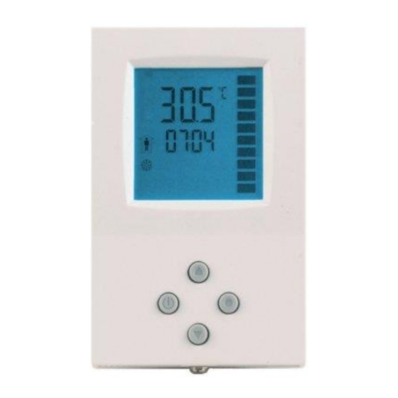
Universal controller TCI-W13-U-H/TCI-W23-U-H
TCI-W13-U-H, TCI-W23-U-H wall mounted universal controller
with internal temperature and humidity sensor
General description
The TCI-W is a stand-alone wall mounted electronic universal controller with two autonomous control loops.
Each control loop may use up to 2 PID sequences and 6 binary sequences. The TCI-W13 features
1 independent control loop, 1 universal input, 1 binary relay output and 2 analog outputs, the TCI-W23 offers
2 independent control loops, 1 universal input, 1 passive input, 1 binary relay output and 2 analog outputs. A
detailed configuration is possible by following a simple setup routine. The TCI can be configured using the
standard operation terminal. No special tool or software is required.
Ordering, name convention
TCI-W23-U
Optional functions and housing
│ │││ └─────
U = 2 x 4" type housing, blank = square housing
Housing
│ ││└───────
In-/outputs:
1 = 1UI, 1DOR, 2AO, 2 = 1UI, 1Passive In, 1DOR, 2AO
│ │└────────
Control loops:
1 = 1 control loop, 2 = 2 control loops
│ └─────────
Mounting:
W = Wall mounted
└──────────── Series indication
TCI
Int.
Int.
Item name
Item code
Loop
UI
temp.
humidity
TCI-W11
40-10 0073
1
1
0
1
TCI-W11-H
40-10 0162
1
1
1
1
TCI-W22
40-10 0075
2
1
0
2
TCI-W22-H
40-10 0077
2
1
1
2
TCI-W13-U
40-10 0174
1
1
0
1
TCI-W13-U-H 40-10 0175
1
1
1
1
TCI-W23-U
40-10 0176
2
1
0
1
TCI-W23-U-H 40-10 0177
2
1
1
1
Accessories
AES1-HT-A2
40-50 0067
1
AES1-HT-A3
40-50 0068
1
AES1-HT-A5
40-50 0069
1
Selection of actuators and sensors
Temperature sensors: Use only our approved NTC sensors to achieve maximum accuracy. Recommended
is SDB-Tn10 as duct sensor, SRA-Tn10 as room sensor.
Modulating actuators: Choose actuators with an input signal type of 0...10 VDC or 4...20 mA. Minimum and
maximum signal limitations may be set in software.
Binary auxiliary devices: E.g. pumps, fans, on/off valves, humidifiers, etc. Do not directly connect devices
that exceed the maximum limits as described under technical data. Observe startup current on inductive
loads.
Jumper configuration
Jumpers are mounted vertically only.
1.
AO - Selection of output signal type:
o
Left position: voltage output (0...10 V), factory default
Right position: current output (0...20 mA)
o
2.
AI - Selection of input signal type:
Left position: voltage input (0...10 V), factory default
o
o
Middle position: current input (0...20 mA)
o
Right position: RT or dry-contact input
Mounting location
Install the controller on an easy accessible interior wall, approx. 1.5 m above the floor in an area of
average temperature.
Avoid direct sunlight or other heat sources, e.g. the area above radiators and heat emitting equipment.
Avoid locations behind doors, outside walls and below or above air discharge grills and diffusers.
Location of mounting is less critical if external temperature sensors are used.
Installation
1.
Connect the wires to be connected to the terminals of the power case according to wiring diagram
2.
Install the mounting plate to the flush mounting box. Make sure that the nipple with the front holding
screw is facing to the ground. Make sure the mounting screw heads do not stand out more than
5 mm (0.2") off the surface of the mounting plate.
3.
Ensure that the jumpers are set correctly.
4.
Slide the two latches located on the top of the front part into the hooks at the upper side of the
mounting plate.
5.
Carefully lower the front part until the interconnector reaches the mounting-plate. Continue
pressing in a gentle way until the front part is fully connected. While inserting the connectors, a
slight resistance can be felt. This is normal. Do not use excessive force!
6.
With a Philips-type screw driver of size #2, carefully tighten the front holding screw to secure the
front part to the mounting plate. This screw is located on the front lower side of the unit. There is no
need to tighten the screw too much.
Doc: 70-00-0384A V1.0 20160523
Technical specification
Warning! This device is intended to be used for comfort applications. Where a device failure endangers human life
and/or property, it is the responsibility of the owner, designer and installer to add additional safety devices to prevent
or detect a system failure caused by such a device failure. The manufacturer of this device cannot be held liable for
any damage caused by such a failure.
Failure to follow specifications and local regulations may endanger life, cause equipment damage and void warranty.
Power supply
Operating voltage
Power consumption
Electrical connection
Clock backup
Signal inputs
Analog inputs
Temperature inputs
DO
TI
AO
Option
relays
0
2
1
Standard
0
2
1
RH Sensor 3%
0
2
1
Schedules
0
2
1
RH Sensor 3%
Humidity sensor AES-HT-Ax:
0
1
2
Standard
0
1
2
RH Sensor 3%
1
1
2
Schedules
1
1
2
RH Sensor 3%
Signal outputs
Analog outputs
RH Sensor 2%
RH Sensor 3%
RH Sensor 5%
Relays outputs
Insulation strength
Environment
Operation
Transport & Storage
A O
U I
Standards
Product standards
█
█
Degree of protection
Pollution class
Safety class
Overvoltage category
Housing
Materials:
General
Dimensions (H x W x D)
Weight (including package)
Power failure
Upon power-interruption, all parameters and set points
are memorized in non-volatile memory, and therefore
do not have to be re-entered.
Error messages
Err1:
An assigned input is not enabled or
missing. All control loops, functions and
outputs tied to this input will be disabled.
Verify input connections, jumper
settings and parameter settings for the
input involved.
Err3:
A function refers to a disabled input.
Disable the function or enable the input.
Err4:
Internal failure. Product must be replaced.
Universal controller TCI-W13-U-H/TCI-W23-U-H
24 VAC 50/60 Hz ± 10%
max. 3 VA
Terminal connectors,
wire 0.34...2.5 mm
2
(AWG 22...13)
24 hours (deluxe version only)
UI1, UI2
DC 0...10V or 0...20mA
Input signal
Resolution
39 mV or 0.078 mA
Voltage: 98kΩ current: 240Ω
Impedance
RT internal, external (Sxx-Tn10 sensor)
Int. NTC: 0...50 °C (32...122 °F)
Range
Ext. NTC: -40...140 °C (-40...284 °F)
Resolution
0.1 K
-40...0 °C (-40...32 °F): 0.5 K
Accuracy
0...50 °C (32...122 °F): 0.2 K
50...100 °C (122...212 °F): 0.5 K
> 100 °C (> 212 °F): 1 K
Capacity sensor
0...100% RH
Range
Measuring accuracy
See figure below
1%
Hysteresis
Repeatability
0.1%
Stability
< 0.5% / year
AO1
DC 0...10V or 0...20mA
Output signal
Resolution
39 mV, 0.078 mA
Voltage: ≥ 5kΩ current: ≤250Ω
Maximum load
Type of disconnection
Micro-interruption
0...48 VAC, 2(1.2)A max. Observe local regulations
AC voltage
0...30 VDC, 2A max.
DC voltage
between relays contacts and system
electronics:
2000VAC to EN 60730-1
To IEC 721-3-3
Climatic conditions
class 3K5
0...50 °C (32...122 °F)
Temperature
Humidity
<95% RH non-condensing
To IEC 721-3-2 and IEC 721-3-1
Climatic conditions
class 3K3 and class 1K3
-25...70 °C (-13...158 °F)
Temperature
Humidity
<95%RH non-condensing
Mechanical conditions
class 2M2
conform according to
EMC Standard
EN 61000-6-1/ EN 61000-6-3
EMEI Standard 73/23/EEC
Automatic electrical controls for
EN 60730-1
household and similar use
special requirement on temperature
EN 60730-2-9
dependent controls
IP30 to EN 60529
II (EN 60 730-1)
II (IEC 60536) if voltage on DO > 48V
III (IEC 60536) if voltage on DO < 48V
I (EN 60730-1)
Cover, back part
Fire proof ABS plastic (UL94 class V-0)
Mounting plate
Galvanized Steel
Front part: 112 x 73 x 15 mm (4.4" x 2.9" x 0.6")
Power case: ø 58 x 32 mm (ø 2.3" x 1.3")
TCI-W13-U-H = 260g (8.1 oz)
TCI-W23-U-H = 270g (9.5 oz)
Relative humidity accuracy
%RH
±5
±4
AES-HT-A5
±3
AES-HT-A3
±2
AES-HT-A2
±1
±0
0
10 20 30 40
50 60 70 80
Figure 1: Max RH-tolerance at 25 °C (77 °F) per
sensor type
© Vector Controls GmbH, Switzerland
Universal controller TCI-W13-U-H/TCI-W23-U-H
Wiring diagram
Warning: Live electrical components!
During installation, testing, servicing and troubleshooting of Vector Controls products, it may be necessary to
work with live electrical components. Have a qualified licensed electrician or other individual who has been
properly trained in handling live electrical components perform these tasks. Failure to follow all electrical
safety precautions when exposed to live electrical components could result in death or serious injury.
0...48VAC, 0...30VDC
24V AC/DC
2
3
G
Q13
1
4
G0
Q14
Y
B1
0V (COM)
0V AC
0...48 VAC, 0...30VDC
24V AC/DC
2
3
G
Q13
1
4
G0
Q14
Y
B1
0V (COM)
0V AC
Description
G0
Power supply:
G
Power supply:
X
Universal input:
U1
X
Passive input:
T2
Y
Binary output:
B1
Y
, X
Analog outputs:
M1
M2
X
Internal temperature input
T1
X
Internal humidity input if AES-HT is inserted
H1
Dimensions mm (inch)
90
100
%RH
X
U1
1
7
X
X
G0
X1
T1
H1
1
5
1
6
TCI-W13-U-H
G0 Y1
G0 Y2
Y
Y
M1
M2
X
X
U1
T2
1
7
1
8
X
X
G0
X1
G0
X2
H1
T1
1
5
1
6
TCI-W23-U-H
G0 Y1
G0 Y2
Y
Y
M1
M2
0V, -24VDC; common for power supply, analog in- and outputs
24VAC, +24VDC
NTC 10kΩ @ 25°C (77 °F) or open contact,
0...10VDC or 0...20 mA (selectable by jumper)
NTC 10kΩ @ 25°C (77 °F) or open contact
Potential free relays contacts (see technical specification)
0...10 V or 0...20 mA (selectable by jumper)
Subject to alterations
Advertisement

Related Manuals for Vector TCI-W13-U-H


Summary of Contents for Vector TCI-W13-U-H
- Page 1 Warning: Live electrical components! and/or property, it is the responsibility of the owner, designer and installer to add additional safety devices to prevent During installation, testing, servicing and troubleshooting of Vector Controls products, it may be necessary to General description or detect a system failure caused by such a device failure.
- Page 2 Press LEFT key again while in the group selection to return to normal operation. The unit will return to normal operation if no key is pressed for more than 5 minutes. Doc: 70-00-0384A V1.0 20160523 © Vector Controls GmbH, Switzerland Subject to alterations...
- Page 3 Hysteresis alarm 5 and 6 (1u), alarms 7 and 8 (2t) 5°C (10°F) 1u 12 2t 12 Calculate a range of inputs (0=not active): 0...4 1= average, 2= minimum, 3= maximum, 4= differential Doc: 70-00-0384A V1.0 20160523 © Vector Controls GmbH, Switzerland Subject to alterations...
- Page 4 5= h/c status loop 1, 6= h/c status loop 2 Fu 21 Cooling activation delay (seconds) 0...1275 Fu 22 Input limit 1 Range acc input Fu 23 Input limit 2 Range acc input Doc: 70-00-0384A V1.0 20160523 © Vector Controls GmbH, Switzerland Subject to alterations...