Table of Contents
Advertisement
Quick Links
TCI-W13, TCI-W23 Series Wall Mounted Universal Controller
Features
•
Universal PID and/or binary control for any analog
input/output signal and range.
•
Multiple auxiliary functions: heat-cool auto changeover,
automatic enable, setpoint compensation.
•
Differential, averaging, min and max functions
•
Cascading of control loops (-W23 type).
•
Alarm monitoring of low and high limits on all inputs.
•
Programmable reaction in case of alarm.
•
Feedback function for inputs and set points.
•
Functions for dehumidifying, set point shift, cascade
control.
•
Password protected programmable user and control
parameters.
•
Blue backlight.
TCI-W23 also includes
•
Power Cap protected real-time clock with 48hr power
backup.
•
Clock with up to 8 switching events
•
7-day programmable schedules, with options including
change of setpoints and direct position of manual outputs.
Applications
•
Fan coil units
•
Heat exchangers
•
Zoning
General
•
TCI-W13: 1 independent control loop, 1 internal temperature sensor, 1 universal input (analog/binary/temp),
1 binary/PWM output, 2 analog outputs
•
TCI-W23: 2 independent control loops, 8 time schedules, 1 internal temperature sensor, 1 universal input,
1 passive input, 1 binary/PWM output, 2 analog outputs
•
Internal temperature sensor standard. Add replaceable humidity element as required: AES3-HT-A2 (2%), AES3-
HT-A3 (3%), or AES3-HT-A5 (5%)
•
Flexible application configuration is made with a parameter-setting routine using the standard operation terminal.
Product Name
- W
T
C
I
2
Types and Ordering
Product
Product No.
Name
TCI-W13
40-10 0259
TCI-W13-H
40-10 0260
TCI-W23
40-10 0263
TCI-W23-H
40-10 0264
AES3-HT-A2
40-50 0102
AES3-HT-A3
40-50 0103
AES3-HT-A5
40-50 0104
Temperature sensors: Use Vector Controls NTC sensors to achieve maximum accuracy:SDB-Tn10-20 (duct), SRA-Tn10
(room), SDB-Tn10-20 + AMI-S10 as immersion sensor.
Actuators: Choose modulating actuators with an input signal type of 0-10 V DC or 4-20 mA (Min. and max. signal
limitations may be set with parameters.3-pointpoint actuators with constant running time are recommended.
Binary auxiliary devices (e.g. pumps, fans, on/off valves, humidifiers, etc): Do not directly connect devices that exceed
specified limits in technical specifications – observe startup current on inductive loads.
Doc: 70-00-0365C, V2.0, 20220523
Subject to alteration
•
VAV
•
Air handlers
•
Fan, Pump control
-
3
U
Housing
In/Outputs:
Control loops:
Mounting:
Series:
Temperature
Humidity
Loop
Sensor
Sensor
(internal)
(internal)
1
1
2
© Vector Controls GmbH, Switzerland
TCI-W13, TCI-W23 Universal Controller
•
Humidifiers
•
Dehumidifiers
•
Ventilation
Blank = square housing
See table below
1 = 1 control loop, 2 = 2 control loops
W = Wall mounted
TCI
Binary
UI
TI
Output
0
0
1
1
1
0
1
1
1
1
1
•
Radiant heating
•
Radiant cooling
•
Pressurization
Time
Analog
Schedules
Output
0
rH Sensor 3% acc.
2
Time schedules
8
rH Sensor 3% acc.
rH Sensor 2% acc.
rH Sensor 3% acc.
rH Sensor 5% acc.
O
VERVIEW
TCI-W13
TCI-W23
Option
Standard
Page 1-22
Advertisement
Table of Contents

Related Manuals for Vector 40-10 0259


Summary of Contents for Vector 40-10 0259
- Page 1 40-50 0104 rH Sensor 5% acc. Temperature sensors: Use Vector Controls NTC sensors to achieve maximum accuracy:SDB-Tn10-20 (duct), SRA-Tn10 (room), SDB-Tn10-20 + AMI-S10 as immersion sensor. Actuators: Choose modulating actuators with an input signal type of 0-10 V DC or 4-20 mA (Min. and max. signal limitations may be set with parameters.3-pointpoint actuators with constant running time are recommended.
-
Page 2: Technical Specifications
Product testing and certification Declaration of conformity Information about the conformity of our products can be found on our website www.vectorcontrols.com on the corresponding product page under "Downloads" Doc: 70-00-0365C, V2.0, 20220523 © Vector Controls GmbH, Switzerland Page 2-22 Subject to alteration... -
Page 3: Wiring And Connection
Wiring and Connection WARNING! Live Electrical Components During installation, testing, servicing and troubleshooting of Vector Controls products, it may be necessary to work with live electrical components. Have a qualified licensed electrician or other individual who has been properly trained in handling live electrical components perform these tasks. Failure to follow all electrical safety... -
Page 4: Mounting Location
Observe local regulations. • Do not mount in a wet or condensation prone environments. Installation instructions See TCI-W installation sheet no. 70-000539 (www.vectorcontrols.com). Dimensions mm (inch) Doc: 70-00-0365C, V2.0, 20220523 © Vector Controls GmbH, Switzerland Page 4-22 Subject to alteration... -
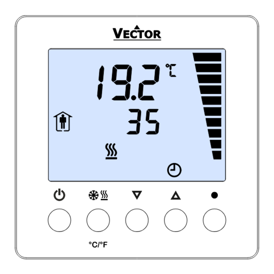
Page 5: Display And Operation
Display of input/output value with 10% resolution (Parameter setting: Displays programming step) Small Digits Display of setpoint, clock or parameter number Large Digits Display of measured room temperature, input or parameter value Doc: 70-00-0365C, V2.0, 20220523 © Vector Controls GmbH, Switzerland Page 5-22 Subject to alteration... -
Page 6: Power Failure
Alarm for low/high input or output limits according to configuration. ALA8 For details on configuring alarms see input configuration on page 11, output configuration on page 15, or auxiliary function on page 18. Doc: 70-00-0365C, V2.0, 20220523 © Vector Controls GmbH, Switzerland Page 6-22 Subject to alteration... - Page 7 For details on sensor input calibration see input configuration on page 11. Identification of software version used Press UP/DOWN buttons simultaneously for three seconds. The display will show firmware version and revision number. Doc: 70-00-0365C, V2.0, 20220523 © Vector Controls GmbH, Switzerland Page 7-22 Subject to alteration...
- Page 8 Characteristics of action (e.g. 0–100% for A1) appear (4 bar indicates step 4 complete) Press UP/DOWN to select characteristic of action, RIGHT to complete Repeat for Pr02 - Pr08 Doc: 70-00-0365C, V2.0, 20220523 © Vector Controls GmbH, Switzerland Page 8-22 Subject to alteration...
-
Page 9: Recommended Set-Up Procedure
Press the POWER to leave the menu. The unit will return to normal operation if no button is pressed for more than 5 minutes. Doc: 70-00-0365C, V2.0, 20220523 © Vector Controls GmbH, Switzerland Page 9-22 Subject to alteration... - Page 10 OFF = Backlight switch on for 30 seconds when a key is pressed. ON/OFF (TCI-W23) ON = Backlight switch on constantly when device is in ON mode Doc: 70-00-0365C, V2.0, 20220523 © Vector Controls GmbH, Switzerland Page 10-22 Subject to alteration...
-
Page 11: Input Configuration
TI2 in – UI1 = TI2 out. It is possible to have multiple differentials on one controller. It is not possible to reverse the subtraction to UI1-TI2. Doc: 70-00-0365C, V2.0, 20220523 © Vector Controls GmbH, Switzerland Page 11-22 Subject to alteration... -
Page 12: Control Loop Configuration
Commonly this is used for humidity control to avoid condensation on outside walls or windows in very cold weather. Doc: 70-00-0365C, V2.0, 20220523 © Vector Controls GmbH, Switzerland Page 12-22 Subject to alteration... - Page 13 Dead zone h/c set points Economy mode set point shift Set point heating/reverse Set point cooling/direct T [°C, °F] PI sequence heating/reverse U [V, mA] PI sequence cooling/direct Doc: 70-00-0365C, V2.0, 20220523 © Vector Controls GmbH, Switzerland Page 13-22 Subject to alteration...
- Page 14 Offset cooling/reverse Dead zone Economy set point shift Set point heating/reverse Set point cooling/direct T [°C, °F] Binary sequences cooling/direct U [V, mA] Binary sequences heating/reverse Doc: 70-00-0365C, V2.0, 20220523 © Vector Controls GmbH, Switzerland Page 14-22 Subject to alteration...
- Page 15 1A03. As the system moves into heating mode, heating airflow increases until it reaches the maximum heating output (1A04), typically 30 to 50% of maximum cooling airflow. Doc: 70-00-0365C, V2.0, 20220523 © Vector Controls GmbH, Switzerland Page 15-22 Subject to alteration...
- Page 16 State functions (1d01=5) activate the output based on certain conditions with or without a demand for heating or ➔ cooling, in either occupied (comfort) or unoccupied (standby) mode. In Energy Hold OFF mode (EHO) the output will be off. Doc: 70-00-0365C, V2.0, 20220523 © Vector Controls GmbH, Switzerland Page 16-22 Subject to alteration...
- Page 17 1) The PWM duty cycle signal is not spanned between the min and max settings. It is just cut off. Any output percentage below the min will be fixed at the minimum time. Any output percentage above the maximum will be fixed to the output maximum. Doc: 70-00-0365C, V2.0, 20220523 © Vector Controls GmbH, Switzerland Page 17-22 Subject to alteration...
-
Page 18: Auxiliary Functions
Limit 2 > Limit 1 Limit 1 > Limit 2 Comfort Comfort Mode Mode Standby Standby Limit Limit Limit Limit Input Input Doc: 70-00-0365C, V2.0, 20220523 © Vector Controls GmbH, Switzerland Page 18-22 Subject to alteration... - Page 19 Limit 1 > Limit 2 Enable Enable Mode Mode Disable Disable Limit Limit Limit Limit Input Input Enable Mode Mode Enable Disable Disable Limit Limit Limit Limit Input Input Doc: 70-00-0365C, V2.0, 20220523 © Vector Controls GmbH, Switzerland Page 19-22 Subject to alteration...
- Page 20 Limit 1, cool to heat at Limit 2. For binary open/close contact, open is a high value (100%), closed is a low value (0%). Limit 2 > Limit 1 Limit 1 > Limit 2 Heat Heat Mode Mode Cool Cool Limit Limit Limit Limit Input Input Doc: 70-00-0365C, V2.0, 20220523 © Vector Controls GmbH, Switzerland Page 20-22 Subject to alteration...
- Page 21 TCI-W13, TCI-W23 Universal Controller Empty page. Doc: 70-00-0365C, V2.0, 20220523 © Vector Controls GmbH, Switzerland Page 21-22 Subject to alteration...
- Page 22 TCI-W13, TCI-W23 Universal Controller Smart Sensors and Controls Made Easy! Quality - Innovation – Partnership Vector Controls GmbH Switzerland info@vectorcontrols.com www.vectorcontrols.com Doc: 70-00-0365C, V2.0, 20220523 © Vector Controls GmbH, Switzerland Page 22-22 Subject to alteration...